A single-phase motor operates using alternating electric current and is connected to single-phase networks. The network must have a voltage of 220 Volts and a frequency of 50 Hertz.
Electric motors of this type are used mainly in low-power devices:
- Household appliances.
- Low power fans
- Pumps.
- Machines for processing raw materials, etc.
Models are available with power from 5 W to 10 kW.
The values of efficiency, power and starting torque for single-phase motors are significantly lower than for three-phase devices of the same size. The overload capacity is also higher for 3-phase motors. Thus, the power of a single-phase mechanism does not exceed 70% of the power of a three-phase mechanism of the same size.
device
Device:
- In fact, it has 2 phases , but only one of them does the work, which is why the motor is called single-phase.
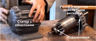
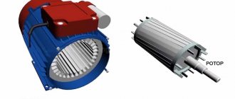
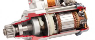
- Like all electric machines , a single-phase motor consists of 2 parts: stationary (stator) and moving (rotor).
- It is an asynchronous electric motor , the stationary component of which has one working winding, connected to a single-phase alternating current source.
The strengths of this type of engine include the simplicity of the design, which is a rotor with a squirrel-cage winding. The disadvantages are low starting torque and efficiency.
The main disadvantage of single-phase current is its inability to generate a magnetic field that performs rotation. Therefore, a single-phase electric motor will not start on its own when connected to the network.
In the theory of electrical machines, the rule applies: in order for a magnetic field to arise that rotates the rotor, there must be at least 2 windings (phases) on the stator. It is also required to shift one winding by a certain angle relative to the other.
During operation, alternating electric fields flow around the windings:
- In accordance with this , the so-called starting winding is located on the stationary section of the single-phase motor. It is shifted 90 degrees relative to the working winding.
- A current shift can be obtained by including a phase-shifting link in the circuit. Active resistors, inductors and capacitors can be used for this.
- 2212 electrical steel is used as the basis
Operating principle and startup scheme
Principle of operation:
- An electric current generates a pulsating magnetic field on the motor stator. This field can be considered as 2 different fields that rotate in different directions and have equal amplitudes and frequencies.
- When the rotor is stationary , these fields lead to the appearance of moments of equal magnitude, but differently directed.
- If the engine does not have special starting mechanisms , then at start the resulting torque will be zero, which means the engine will not rotate.
- If the rotor is rotated in one direction , then the corresponding torque begins to prevail, which means that the motor shaft will continue to rotate in the given direction.
Launch scheme:
- The launch is carried out by a magnetic field , which rotates the moving part of the motor. It is created by 2 windings: main and additional. The latter is smaller in size and is a launcher. It is connected to the main electrical network through capacitance or inductance. The connection is made only during start-up. In low power motors, the starting phase is short-circuited.
- The engine is started by holding the start button for a few seconds, as a result of which the rotor accelerates.
- When the start button is released , the electric motor switches from two-phase mode to single-phase mode, and its operation is supported by the corresponding component of the alternating magnetic field.
- The starting phase is designed for short-term operation – usually up to 3 s. A longer time under load can lead to overheating, insulation fire and mechanism failure. Therefore, it is important to release the start button in a timely manner.
- In order to increase reliability, a centrifugal switch and a thermal relay are built into the housing of single-phase motors.
- The function of the centrifugal switch is to cut off the starting phase when the rotor reaches its rated speed. This happens automatically - without user intervention.
- The thermal relay turns off both phases of the winding if they heat up above the permissible level.
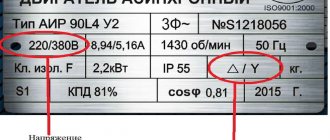
Connection diagram "Triangle"
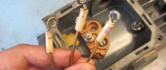
The connection itself is relatively easy; the current-carrying wire is connected to the starting capacitor and to the motor (or motor) terminals. That is, if we take it more simply, there is a motor; it contains three conductive terminals. 1 – zero, 2 – working, 3 – phase.
The power wire is stripped and there are two main wires in a blue and brown winding, the brown one is connected to terminal 1, one of the capacitor wires is also connected to it, the second capacitor wire is connected to the second working terminal, and the blue power wire is connected to the phase.
If the motor power is small, up to one and a half kW, in principle only one capacitor can be used. But when working with loads and high powers, it is mandatory to use two capacitors; they are connected in series, but between them there is a trigger mechanism, popularly called “thermal”, which turns off the capacitor when the required volume is reached.
You need to understand that the motor winding itself already has a star connection, but electricians use wires to turn it into a delta. The main thing here is to distribute the wires that go into the junction box.
Connection diagram “Triangle” and “Star”
Connection
To operate the device, 1 phase with a voltage of 220 Volts is required. This means that you can plug it into a household outlet. This is precisely the reason for the popularity of the engine among the population. All household appliances, from a juicer to a grinder, have mechanisms of this type.
connection with starting and running capacitors
There are 2 types of electric motors: with a starting winding and with a working capacitor:
- In the first type of device , the starting winding operates via a capacitor only during start. Once the machine reaches normal speed, it turns off and operation continues with one winding.
- In the second case , for motors with a working capacitor, the additional winding is permanently connected through the capacitor.
An electric motor can be taken from one device and connected to another. For example, a working single-phase motor from a washing machine or vacuum cleaner can be used to operate a lawn mower, processing machine, etc.
There are 3 schemes for switching on a single-phase motor:
- In scheme 1 , the work of the starting winding is performed by means of a capacitor and only for the starting period.
- 2 circuit also provides for a short-term connection, but it occurs through a resistance and not through a capacitor.
- Scheme 3 is the most common. In this scheme, the capacitor is constantly connected to a source of electricity, and not just during startup.
Connecting an electric motor with starting resistance:
- The auxiliary winding of such devices has increased active resistance.
- To start an electrical machine of this type, a starting resistor can be used. It should be connected in series to the starting winding. Thus, it is possible to obtain a phase shift of 30° between the winding currents, which will be quite enough to start the mechanism.
- Alternatively , a phase shift can be obtained by using a starting phase with a higher resistance value and a lower inductance value. This winding has fewer turns and thinner wire.
Read also: How to check the armature of a VAZ 2107 generator
Connecting a motor with a capacitor start:
- For these electric machines, the starting circuit contains a capacitor and is turned on only for the start period.
- To achieve the maximum starting torque, a circular magnetic field is required that performs the rotation. For it to occur, the winding currents must be rotated 90° relative to each other. Phase-shifting elements such as a resistor and inductor do not provide the necessary phase shift. Only the inclusion of a capacitor in the circuit allows you to obtain a phase shift of 90°, if you select the capacitance correctly.
- calculate which wires belong to which winding by measuring the resistance. For the working winding, its value is always less (about 12 Ohms) than for the starting winding (usually about 30 Ohms). Accordingly, the cross-section of the working winding wire is larger than that of the starting winding.
- The capacitor is selected according to the current consumed by the motor. For example, if the current is 1.4 A, then a capacitor with a capacity of 6 μF is required.
Connection diagram for an asynchronous motor with a starting winding: assembly sequence
For example, we have determined that there are four or three wires coming out of the stator. We call up the active resistance between them with an ohmmeter and determine the starting and operating windings.
Let’s assume that four wires have two pairs with resistances of 6 and 12 ohms connected to each other. Let's randomly twist one wire from each winding, designate this place as a “common wire” and get a measurement of 6, 12, 18 Ohms between the three terminals.
I marked the beginnings of the windings with dots on this diagram. For now, ignore this question. But, you will need to return to it further when the need arises to reverse.
The chain between the common terminal and the lower resistance 6Ω will be the main one, and the larger 12Ω will be the auxiliary, starting winding. Connecting them in series will show a total result of 18 ohms.
We mark these 3 ends with markings that are already clear to us:
Next we need a PNVS button, specially designed for starting single-phase asynchronous motors. Its electrical circuit is represented by three closing contacts.
But, it has an important difference from the start button of three-phase NVD electric motors: its middle contact is made with self-return, and not fixed when pressed.
This means that when the button is pressed, all three contacts are closed and held in that position. But, when you release your hand, the two outer contacts remain closed, and the middle one returns under the action of the spring to the open state.
We connect this button and the terminals for the output of the stator windings from the electric motor with a three-core cable so that the starting winding contact goes to the middle contact of the PNVS. We connect pins P and P to its outermost contacts and mark them.
Functionality check
How to check engine performance by visual inspection?
The following are defects that indicate possible problems with the engine; they could be caused by improper operation or overload:
- Broken support or mounting gaps.
- in the middle of the engine has darkened (indicates overheating).
- through cracks in the housing.
To check the performance of the engine, you should first turn it on for 1 minute, and then let it run for about 15 minutes.
If after this the engine is hot, then:
- Perhaps the bearings are dirty, jammed, or simply worn out.
- The reason may be that the capacitor capacitance is too high.
Disconnect the capacitor and start the motor manually: if it stops heating, you need to reduce the capacitor capacitance.
Model overview
One of the most popular are electric motors of the AIR series. There are models made on feet 1081, and models of combined design - feet + flange 2081.
Electric motors in the foot + flange design will cost about 5% more than similar ones with feet.
As a rule, manufacturers provide a warranty of 12 months.
For electric motors with a rotation height of 56-80 mm, the frame is made of aluminum. Motors with a rotation height of more than 90 mm are available in cast iron.
Models differ in power, rotation speed, height of the rotation axis, and efficiency.
The more powerful the engine, the higher its cost:
- An engine with a power of 0.18 kW can be purchased for 3 thousand rubles (electric motor AIRE 56 B2).
- A model with a power of 3 kW will cost about 10 thousand rubles (AIRE 90 LB2).
The height of the rotation axis for motors with 1 phase varies from 56 mm to 90 mm and directly depends on the power: the more powerful the engine, the greater the height of the rotation axis, and therefore the price.
Different models have different efficiencies, typically ranging from 67% to 75%. Greater efficiency corresponds to a higher cost of the model.
You should also pay attention to engines produced by the Italian company AACO, founded in 1982:
- Thus, the AACO series 53 electric motor is designed specifically for use in gas burners. These motors can also be used in washing installations, warm air generators, and central heating systems.
- Electric motors of the 60, 63, 71 series are designed for use in water supply installations. Also, the company offers universal motors of the 110 and 110 compact series, which are distinguished by a diverse range of applications: burners, fans, pumps, lifting devices and other equipment.
You can buy motors produced by AACO for a price starting from 4,600 rubles.
First, let's find out the type of engine. We will not always resolve the issue unambiguously. Appearance says little; the nameplate of an old engine may not correspond to the actual contents of the unit. We propose to briefly consider what asynchronous and commutator motors the industry produces. We will tell you the differences in operation, key properties, external and internal. Let's discuss connecting a single-phase motor to an AC mains.
Brushed vs asynchronous motors
The question - commutator motor or asynchronous - is resolved as a matter of priority. The process is simple. A collector is a drum divided by copper sections, approximately rectangular in shape, made of copper. Forms a current collector; in commutator motors, the rotor is always powered by electric current. Constant, variable - the field is created by the applied voltage.
The commutator motor contains at least two brushes. We rarely see three-phase ones. Information about such units is described in literature from the middle of the last century. Three-phase commutator motors were used, regulating the shaft rotation speed over a wide range. The motor of this type is equipped with brushes and a copper drum divided into sections. It is difficult to miss the sign even with the naked eye. Examples of commutator motors:
- Vacuum cleaner, washing machine.
- Grinder, drill, electric hand tool.
Commutator motors are widely used, providing a relatively simple reverse, realized by changing the commutation of the windings. The speed is regulated by changing the supply voltage cutoff angle or amplitude. Common disadvantages of commutator motors include:
- Noisy. Friction by drum brushes cannot occur silently. When crossing the section, sparking occurs. The effect causes radio frequency interference, producing a host of extraneous sounds. Commutator motors are relatively noisy. Try to remember the vacuum cleaner. Is the washing machine not so loud when performing the washing cycle? Low speed brushed motors are good.
- The need for maintenance is determined by the presence of rubbing parts. The current collector is often contaminated with graphite. It is simply unacceptable; it can short-circuit adjacent sections. Dirt increases noise levels and other negative effects.
Everything is good in moderation. Brushed motors will allow you to obtain a given power (torque) at the start, after acceleration. It is relatively easy to adjust the speed. The reason for the fascination of household appliances with commutator varieties has been named; asynchronous motors are the heart of equipment that has increased requirements for sound pressure levels. Fans, hoods. Serious loads will require major design changes. Cost, size, and complexity increase, making production unprofitable.
A commutator engine is distinguished by the presence of... a commutator. Even if you cannot see it from the outside (hidden by the casing), we will notice the indispensable graphite brushes, pressed by springs. The part requires replacement over time; it will help to distinguish a commutator motor from an asynchronous one.
Single-phase and three-phase asynchronous motors
We agreed - three-phase commutator motors are difficult to obtain; the current section concerns asynchronous machines. We list the varieties:
- Three-phase asynchronous motors are equipped with a number of outputs from three to six working windings minus various fuses, internal relays, and various sensors. The stator coils inside are connected by a star, making it impossible to directly connect to a single-phase network.
- Single-phase motors equipped with a starting winding are, among other things, equipped with a pair of contacts leading to a centrifugal limit switch. The miniature device breaks the chain when the shaft is untwisted. The starting winding catalyzes the initial stage. Further action will interfere, reducing the efficiency of the engine. The design is usually called bifilar. The starting winding is wound with double wire, reducing reactance. Helps reduce the capacitance of the capacitor - critical. A striking example of single-phase asynchronous motors with a starting winding are the compressors of household refrigerators.
- The capacitor winding, different from the starting winding, operates continuously. We will find the motors inside the floor fans. The capacitor provides a phase shift of 90 degrees, allowing you to choose the direction of rotation and maintain the desired shape of the electromagnetic field inside the rotor. Typically the capacitor is mounted on the motor housing.
Read also: Reverse starting circuit for 380 engine
Three-phase asynchronous motors
Let's learn how to distinguish single-phase asynchronous motors from three-phase ones. In the latter case, there are always three equal windings inside. Therefore, you can find three pairs of contacts that, when examined by a tester, give the same resistance. For example, 9 ohms. If the windings are connected by a star inside, there will be three terminals with the same resistance. Of these, any pair gives identical readings displayed on the multimeter screen. The resistance is equal to two windings each time.
Because current must flow out, sometimes a three-phase motor has a neutral terminal. The center of the star, with each of the other three wires, gives identical resistance, half that shown by the pairwise continuity. The above symptoms speak eloquently: the motor is three-phase, alien to the topic of today’s conversation.
The winding motors discussed in this section contain two. One starting or capacitor (auxiliary). There are usually three or four conclusions. If there is no capacitor decorating the case, you can try to reason, puzzled by the purpose of the contacts, as follows:
- There are four pins - you need to measure the resistance. Usually they ring in pairs. The resistance is lower - we found the main winding connected to a 230 volt network without a capacitor. Polarity does not matter; the direction of rotation is set by the way the auxiliary winding is turned on, by switching the coils. Simply put, connect a single-phase electric motor of a characteristic type with only one main winding - in the initial period of time the shaft stands upright. Wherever you spin, there will be rotation. Beware of starting with your hand - it will break.
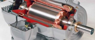
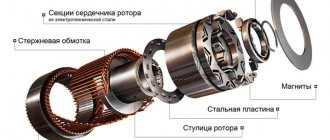
Asynchronous motor device
What is a capacitor
This part contains two metal plates, between which there is a dielectric layer. When voltage is applied to the plates, a charge accumulates on them. The electrical is inside the capacitor. The stronger the charge is on the plates, the stronger it is.
If you disconnect the voltage from the plates, the capacitor begins to release charge. If alternating current is used, the polarity of the voltage will periodically change. In this case, the plates will alternately have a positive and a negative charge.
The capacitance of a capacitor is its most important characteristic. It characterizes how much energy he is able to pass through himself. It is measured in farads. Since we are talking about a very large quantity, prefixes are usually used to indicate how small a part is used. The most commonly used is microfarads (this unit is equal to 0.000001 farads).
Motor connection procedure Source kabel-house.ru
There is a voltage rating for each capacitor. With it, this part is able to work for a long time and reliably. The maximum operating time value, which is expressed in the number of hours, must be indicated.
There are different types of capacitors:
- Polar are designed for use in DC circuits. An important feature is the need to connect in accordance with the polarity indicated on them. They are usually small in size and have a relatively large capacity.
- Non-polar ones can be connected regardless of polarity. They are used in alternating current circuits. They are larger in size than the polar ones.
- Electrolytic. They use sheets of foil as plates, and the dielectric is a thin layer of oxide.
Electrolytic ones are best suited for use as a starting capacitor. They are often used with an AC frequency of 50 Hz and a voltage of 220-600 volts. Capacitors can have a fairly high capacity; it can be hundreds of thousands of microfarads.
These parts are highly vulnerable to overheating. If the thermal regime is violated, they quickly fail. Non-polar capacitors do not have this disadvantage, but are several times more expensive.
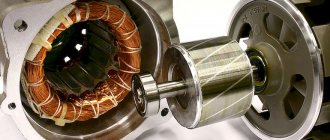
Single-phase asynchronous motor Source asutpp.ru
When connected in parallel, the containers add up. In the event that it is not enough, you can connect an additional part in parallel to increase it. In this situation there is no need to reassemble the trigger circuit.
Other types of capacitors are also used. For example, these can be vacuum, liquid, gas and others. However, they are not used as starting capacitors.
Sometimes the capacitor that is included in the design fails to start. In this case, it is recommended to remove it and replace it with one that has a larger capacity. For low-power motors, it is permissible for one capacitor to perform the functions of working and starting.
The use of polar capacitors in alternating voltage conditions is possible when the connection is made through a diode. Now the polarity of the contacts will not change. However, if the diode is faulty, the part will fail.
Construction of an asynchronous motor Source elektrikexpert.ru
Distinguishing types of single-phase motors in practice
Let's learn how to distinguish a bifilar motor from a capacitor motor. It should be said that the difference is purely nominal. The connection diagram for a single-phase motor is similar. The bifilar winding is not designed to operate continuously. It will interfere and reduce efficiency. Therefore, it is interrupted after a set of revolutions by a start-up relay (inherent in household refrigerators) or by centrifugal switches. It is believed that the starting winding operates for several seconds. According to generally accepted standards, it will launch 30 times per hour, lasting 3 seconds each. Then the coils may overheat (burn out). The reason that limits the starting winding being energized.
The difference is nominal, but professionals note an interesting feature by which they judge whether we have a bifilar or capacitor motor. Auxiliary winding resistance. The nominal value differs from the working one by more than 2 times, most likely the engine is bifilar. Accordingly, the winding is starting. A capacitor motor operates using the services of two coils. Both are constantly under tension.
Single phase asynchronous motor
The test must be carried out carefully; in the absence of thermal fuses and other means of protection, the starting winding may burn out. You will have to unscrew the shaft manually, which is clearly not an easy task. Sometimes it is advisable to connect a single-phase asynchronous motor to a single-phase network using a similar circuit, as was done in previous equipment. An ordinary refrigerator is equipped with a start-up relay, a separate topic of discussion. The parameters of the device are closely related to the type of engine used; mutual replacement is not possible in every case (violation of a simple rule can cause breakdown).
Let us mention it twice: there can be three or four winding terminals. The number is not informative. A pair of thermal fuse contacts is acceptable. Plus the above, including the centrifugal switch. In the case of continuity, the resistance is either low, or vice versa - we fix the gap. By the way, do not forget to test each end of the coil against the body when determining the resistance. Insulation is standard not lower than 20 MOhm. Otherwise, you should think about the presence of a breakdown. We also assume that a three-phase motor with internal star-type winding commutation may have a neutral output to the housing. In this case, the motor requires an indispensable grounding, for which a terminal is provided (but it is more likely that the motor simply failed due to an insulation breakdown).
Electromagnetic relay for disconnecting the starting capacitance of a capacitor single-phase motor
There are 2 types of single-phase asynchronous motors - bifilar (with a starting winding) and capacitor. Their difference is that in bifilar single-phase motors the starting winding operates only until the motor accelerates. Afterwards it is turned off by a special device - a centrifugal switch or a start-up relay (in refrigerators). This is necessary because after overclocking it reduces efficiency.
In capacitor single-phase motors, the capacitor winding runs all the time. Two windings - the main and auxiliary, they are shifted relative to each other by 90°. Thanks to this, you can change the direction of rotation. The capacitor on such engines is usually attached to the housing and is easy to identify by this feature.
Connection diagrams for an operating voltage of 380 V
Industrially produced asynchronous three-phase motors can be connected in two main ways:
- star connection";
- delta connection".
Electric motors are structurally made of a movable rotor and a housing into which a stationary stator is inserted (can be assembled directly in the housing or inserted there). The stator consists of 3 equal windings, wound in a special way and located on it.
In a star connection, the ends of all three motor windings are connected together, and three phases are supplied to their beginnings. When connecting windings in a triangle, the end of one is connected to the beginning of the next.
How to choose a capacitor for starting a single-phase motor
We have already told you how to select a capacitor for starting a three-phase motor, but the method is not suitable in our case. Amateurs recommend trying to enter the so-called resonance. In this case, the consumption of a 9 kW unit will be about (!) 100 W. This does not mean that the shaft will pull the full load, but in idle mode the consumption will be minimal. How to connect an electric motor this way.
Amateurs recommend focusing on current consumption. At the optimal capacity value, the power will be minimal. You can estimate the current consumption using a Chinese multimeter. And so, the connection of a single-phase motor with a starting winding is carried out, guided by the electrical diagram indicated on the housing. For example, there is information there:
- The color of the cambric of a certain winding.
- Electrical switching diagram for an alternating current circuit.
- Nominal capacity used.
Read also: How to unsolder a part from a board with a soldering iron
So, if you take a single-phase asynchronous motor, the connection diagram is often indicated on the housing.
The question of how to connect a single-phase electric motor very often arises in practice due to the high popularity of using such units for solving various household problems.
The connection diagram for a single-phase electric motor is quite simple and requires taking into account only one fundamental point: to ensure its operation, a rotating magnetic field is necessary. If there is only a single-phase alternating current network at the time of starting the electric motor, it must be formed artificially through the use of appropriate circuit solutions.
- Electric motor windings
- Features of torque formation
- Capacitors
- Indirect inclusion
- Features of using a magnetic starter
- Conclusion
Replacement and selection of starting/running capacitor
If you have an original capacitor, then it is clear that you simply need to put it in place of the old one and that’s it. Polarity does not matter, that is, the terminals of the capacitor do not have the designations plus “+” and minus “-” and they can be connected in any way. It is strictly forbidden to use electrolytic capacitors (you can recognize them by their smaller sizes, with the same capacity, and the plus and minus markings on the case). As a consequence of application - thermal destruction. For these purposes, manufacturers specially produce non-polar capacitors for operation in an alternating current circuit, which have convenient mounting and flat terminals for quick installation.
If the required value is not available, then it can be obtained by connecting capacitors in parallel. The total capacitance will be equal to the sum of the two capacitors:
That is, if we connect two 35 μF capacitors, we get a total capacity of 70 μF, the voltage at which they can operate will correspond to their rated voltage.
Electric motor windings
Laying windings in the stator of a single-phase electric motor
The design of any single-phase electric motor requires the use of at least three coils. Two of them are stator structural elements connected in parallel. One of them is working, and the second serves as a launcher. Their terminals are located on the motor housing and are used to connect to the network. The rotor winding is short-circuited. Two of them will be connected to the network, the rest are used for switching.
To change the power, the working coil can be formed from two parts, which are connected in series.
You can visually identify the working and starting windings by the cross-section of the wire: for the first of them it is noticeably larger. You can measure the resistance with a tester by connecting it to the terminals: at the working winding its value will be less. As a rule, the resistance of the windings will be no more than several tens of ohms.
Connection diagram for a three-phase motor via a capacitor
Here, the voltage of 220 volts is distributed into 2 series-connected windings, where each is designed for this voltage. Therefore, the power is lost almost twice, but such an engine can be used in many low-power devices.
The maximum power of a 380 V motor in a 220 V network can be achieved using a delta connection. In addition to minimal power losses, the engine speed also remains unchanged. Here, each winding is used for its own operating voltage, hence the power.
It is important to remember: three-phase electric motors have higher efficiency than single-phase 220 V motors . Therefore, if there is a 380 V input, be sure to connect to it - this will ensure more stable and economical operation of the devices. To start the motor, you will not need various starters and windings, because a rotating magnetic field appears in the stator immediately after connecting to a 380 V network.
Features of torque formation
The magnetic field created by the motor coils has a phase shift of 90 degrees. This is usually achieved through a capacitor that is connected in series with the trigger circuit. Possible connection options are shown in the figure below.
Options for creating a phase shift
The trigger coil can operate continuously. A scheme based on its shutdown after reaching the rated rotor speed is also acceptable. The permanent connection of the starting winding complicates the design of the motor, but improves its performance. These differences do not affect the characteristics of connecting to the network.
To simplify starting an engine with a working capacitor, before applying current to it from the network, an auxiliary capacitance is connected in parallel to it.
A single-phase electric motor allows you to simply change the direction of shaft rotation to the opposite direction. To do this, the phase of the current coming from the network and flowing through the starting circuit is shifted to the opposite one. This procedure is implemented by simply changing the order in which the starting winding is turned on when it is connected to the working winding.
What is a starting capacitor
When the electric motor is in operating mode, its movement is provided by the windings. However, when at the moment of start you need to start rotating, the usual engine efforts are not enough. Without the use of additional means, it will only begin to tremble slightly.
Typically one of the engine elements is a run capacitor. It accumulates a charge that is capable of exceeding the operating voltage, and then releases it at the right moment. However, its work is not enough to start it. To do this, you need to connect another capacitor in parallel, which is called a starting capacitor.
Selection of a working capacitor Source sdelaysam-svoimirukami.ru
It is launched for a short time, which does not exceed a few seconds. Sometimes this is done by briefly pressing the start button, and sometimes the shutdown is done automatically after the engine begins to pick up speed.
The use of a starting capacitor is especially important in cases where the engine needs to be started under load. In this case, it will be necessary to increase the starting torque during the first seconds of operation.
In some cases, the engine is started with a light load. In this case, a starting capacitor may not be needed. This applies to motors whose power does not exceed 1 kW. Refusal to use it will simplify the scheme and reduce costs. Sometimes the load can be related to design features. In this case, you can take measures to reduce it, which will make it easier to start the engine in the future.
Various starting capacitors Source antemion.ru
Capacitors
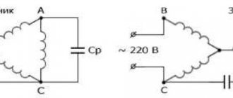
Connection diagram for single-phase capacitor motors: a – with working capacitance Cp, b – with working capacitance Cp and starting capacitance Sp.
The electric motor can be equipped with two types of capacitors. The presence of a capacitance connected in series with the trigger winding and passing current through it to shift the phase is mandatory. Its value is borrowed from the motor’s passport data and is duplicated on its nameplate.
If a capacitor of the required capacity is not available, it is permissible to use any other with a similar rating. If the deflection is too much downward, the engine may not start to rotate without manually cranking the shaft, and then will not develop the required power. If the capacity is significantly exceeded, intense heating will begin.
The capacity of the additional starting component is selected two to three times higher than the main one. This value provides maximum starting torque.
To turn on the trigger element, either a regular button or more complex circuits can be used.
Wiring diagram for an asynchronous motor with capacitor start: 3 technologies
The stator with windings for starting from capacitors has approximately the same design as discussed above. It is difficult to distinguish it by appearance and simple measurements with a multimeter, although the windings may have equal resistance.
Refer to the nameplate and table from Aliyev’s book. You can try to connect such an electric motor using a circuit with a PNVS button, but it will not spin up.
It will not have enough starting torque from the auxiliary winding. It will hum and twitch, but will not reach the rotation mode. Here you need to assemble a different capacitor starting circuit.
The 2 ends of different windings are connected to a common terminal O. A household voltage of 220 volts is supplied to it and the second end of the working winding through an AB switching device.
The capacitor is connected to the terminals of the starting and operating windings.
As a switching device, you can use a double circuit breaker, a switch, NVD or NVDS type buttons.
Here it turns out that:
This circuit is used for easy starting of capacitor electric motors that are put into operation without heavy load on the drive, for example, fans, sanders.
If, at the moment of starting, it is necessary to simultaneously spin the belt drive, gear mechanism of the gearbox or other heavy drive, then a starting capacitor is added to the circuit, which increases the starting torque.
It is convenient to describe the operating principle of such a scheme using the same PVS button.
Its self-resetting contact is connected to the auxiliary winding through an additional starting capacitor Sp. The second end of its plate is connected to terminal P and working capacity Cp.
An additional capacitor at the moment of starting an electric motor with a heavy drive helps it quickly reach its rated rotation speed, and then simply turns off so as not to create overheating of the stator.
This circuit is fraught with one danger associated with long-term storage of a capacitive charge by the starting capacitor after removing power 220 when the electric motor is turned off.
If the worker is not careful or careless, the discharge current can pass through the human body. Therefore, the charged capacity must be discharged.
In the scheme under consideration, after removing the voltage and pulling out the plug and power cord from the socket, this can be done by briefly turning on the PVS button. Then the capacitance Sp will begin to discharge through the starting winding of the motor.
However, not all people do this for various reasons. Therefore, it is recommended to install two additional resistors in the starting circuit.
Resistance Rр is selected with a nominal value of about 300÷500 Ohms of several watts. Its task is to discharge the auxiliary capacitance Sp after removing the supply voltage.
The Ro resistor is low-resistance and powerful and acts as a current-limiting resistance.
Where can I get the values of the main and auxiliary capacitors?
The fact is that the factory determines the value of the starting and operating capacitance for capacitor starting of a single-phase IM individually for each model and indicates this value in the passport.
There are simply no separate formulas for calculating how it is done for capacitor starting of a three-phase motor in a single-phase network using star or delta circuits.
You will need to look for factory recommendations or experiment during the setup process with different containers, choosing the most optimal option.
The owner of the video “IV I'm Interested” shows how to optimally configure the parameters of a capacitor motor starting circuit.
Indirect inclusion
Connecting a single-phase motor
The main component of the indirect connection circuit is a magnetic starter, which is connected to the gap between the power network output and the electric motor.
The power contacts of this block are designed as normally open. Based on the maximum current flowing through it, a magnetic starter belongs to one of seven standardized groups. Due to the low power of single-phase electric motors, a device of the first group is usually sufficient, the maximum switching current of which is 10 A.
The control part of the coil is designed for connection to networks with different voltages. The most convenient is a magnetic starter controlled from 220V AC.
Features of using a magnetic starter
The control part of the device has several pairs of contacts on which the relay automation circuit is assembled. One of them is always normally closed, and the second is always normally open.
The “Start” button has a normally open contact, while the “Stop” button has a normally closed element.
When connecting the device in question, several types of connections are made.
Single-phase motor connection diagram
The phase, along with the input terminal, is also connected to the contact input of the “Stop” button, and the zero is connected to the input terminal of the coil, which ensures that control current flows through it.
The active contact of the “Start” button when the engine is running is bypassed by a similar element of the coil. To form this circuit, two additional connections are made, the diagram of which is shown in the figure above:
- the output of the working contact of the “Stop” button is connected in parallel with the output contacts of the “Start” button and the input of the control coil;
- the output of the normally open contact of the control coil is connected in parallel to its output terminal and to the input of the working contact of the “Start” button.