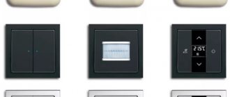
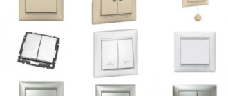
Types of switches and operating principles
Based on the number of switched chains and the number of keys, all existing types of switches are divided into the following types:
- single-key models;
- two-key samples;
- three-key devices.
Another type of old device is still in use, in which the element that controls the switch mechanism is more like a button.
In addition, rare types of rotary-type switching products are presented on the domestic market. In terms of control method, they are a bit like a packet switch. There are also inexpensive Chinese devices related to touch sensitive devices. To control them, you don’t need much effort - just put your finger on the contact plate.
The operating principle of a conventional type switch is based on the closure of the moving and fixed contacts when the key is moved to the upper position and their opening when the reverse action occurs. The so-called “pass-through” switch works in the same way, differing from the usual one in the presence of additional groups of contacts, as well as in the method of inclusion in the lighting network.
Device
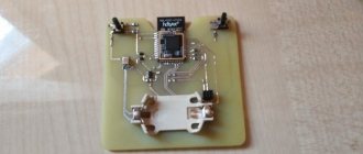
Before installing the switch, let's look at how this switching device works. Let's do this using the example of the simplest single-key light switch. The most important part of this device is the operating mechanism. It is a metal frame on which a drive is attached, which directly turns the device on and off. Essentially, this drive is a moving contact that connects two fixed contacts of the switch.
It will be interesting➡ Description of the electrical circuit diagram with an example
One fixed contact is incoming, a wire from the power supply is connected to it, the second is outgoing, and the wire is connected to the lamp. The correct position of these two fixed contacts is open, in which case the switch is considered to be off, the circuit between the power supply and the lamp is not closed, and the lamp does not light. As soon as the switch drive is affected, the movable contact takes a position in which it closes a circuit between two fixed contacts, voltage is supplied from the power source to the light bulb and it lights up.
Operating mechanism of the switch.
For safety reasons, the entire contact part is placed in some kind of dielectric (it can be plastic or porcelain). The switch is installed in wall holes, but before this, special socket boxes must be installed in the holes made in the wall. And the working mechanism of the switches is already fixed in them. Their reliable fixation is ensured by sliding legs located on the sides of the working part.
Another design component of switches is protective elements. As a rule, they are made of plastic. The first of these elements is a key; it is attached to the drive of the working part and directly controls the switching device. The second element is a protective frame; it covers the working part and prevents a person from touching the live contacts of the switch. The frame is secured with screws or plastic latches.
Causes of breakdowns
A faulty switch can be determined by the following signs:
- when you press a key or turn a toggle switch, knob, or other actions, the light does not turn on;
- turning on or off operations require multiple repetitions, keys or other elements work with jamming;
- an increase in the temperature of the light switching device housing is felt;
- after the circuit is closed, a crackling sound is heard or the lamp flickers;
- frequent burnout of light bulbs, regardless of their type (incandescent, LED, halogen, etc.);
- when the contacts in the switch close, a crackling sound is produced;
- The device does not connect to the network.
These problems may occur due to the following faults:
- Destruction of individual elements of the switch or melting of contacts.
- Violation of integrity and contact in the place of fixation of electrical wiring or terminals.
- The housing in the contact group is destroyed.
- The contact group is worn out.
The basic principle of operation of any type of switch is that it closes to turn on the light and opens the contacts to turn it off. However, often in more complex switch configurations, breakdowns can be even minor, which will prevent the luminaire circuit from closing.
Ways to switch the light
Apartment switches can be controlled by:
- by pressing a key
- by switching the toggle switch
- by pulling or releasing the cord (chain)
- moving the slider
- turning on the button
- built-in motion sensor
- touch panel
- intensity of the incident light flux
- remote control
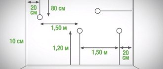
They are most often installed on the wall for external or internal installation of electrical wiring. With the hidden placement method, the switch is hidden in a socket inside the wall, and the wires are connected to the terminals after the housing is secured. For open wiring, use a socket box. The base is attached to it with screws.
Keyboard designs
Keyboard light switches are classics of the genre. This type is the leader in the electrical products market and is most often used for connecting lamps. The principle of operation is quite simple - the circuit is closed when the rocker key is pressed. There are one-, two- and three-key models. Structurally, the light switch, controlled by pressing a key, consists of contacts permanently fixed in the housing and a movable swinging mechanism, pressed by a spring operating on:
- compression
- stretching
In the first case, the pressing force on the key is transferred to the ball, which compresses the spring. It slides along the rocker arm's swing axis, rolls over its shoulder and moves the moving mechanism with contacts in the opposite direction.
In the second method, a frame is attached to the switch key, pressed by a spring to the base. It swings around an axis and with its movement creates or breaks an electrical contact.
In both cases, the moving part, under the action of a spring, switches the switch from one state to another, depending on where the lower or upper part of the key is pressed. With correctly selected electrical parameters and compliance with operating conditions, the switch can operate without failure for many decades. Household switches have a small load capacity, designed to turn on one to several light sources simultaneously. They are designed for a load current of up to 10-15 A. It is no longer possible to switch a more powerful load with such devices in their pure form.
The advantage of this type of switches:
- low price
- convenient use
- easy repair, installation and replacement
There are no particular shortcomings.
Changeover and pass-through switches
They are a type of flip-flop keyboard design. When the key is manipulated, one of the two lamps connected to them lights up. Most often, such models are used to control light from several remote locations. At the moment the circuit opens, an ordinary switch (no matter how many keys it has) only breaks the circuit, the switch also breaks the circuit, but at the same time another circuit is immediately closed.
Pass-through switches are devices designed to provide control of a single light source from two or more different locations. Schemes using them are somewhat more complex than traditional ones, since they involve the installation of several switching devices. Lighting using walk-through switches is usually installed in long corridors, on stairs, garden paths, and in bedrooms. This scheme allows you to turn on the light at one end of the room and turn it off at the other without returning to the first switch. Read more about pass-through switches in our article.
Cord switches
Such models were massively installed inside multi-story panel buildings in the 70s and 80s. If used properly, they continue to work today. The peculiarity of their device is a nylon cord hanging down from the body, which is tied to a rotary lever connected to a movable contact block. The return of the block is ensured by the compression energy of the spring after the cord is released. Among similar models, there are designs that, by pulling the cord (turning the lever), control two groups of chandelier lamps: with the first pull, one block of lamps is turned on, with the second, another, and then they are turned off sequentially.
Floor lamps, wall sconces and table lamps are often equipped with just this type of switch: a cord hanging from under the lampshade with an elegant sleeve-handle. By the way, in modern Great Britain this device is still the only one approved for installation in bathrooms: it is believed that the inability to even accidentally touch the electrical content of the device or its live parts ensures safety.
For reasons of aesthetics, switches of this type are installed in interiors in retro, classicism, baroque and modernist styles. And if just a few decades ago, electricians received orders to re-equip old-built apartments with push-button switches instead of “outdated” rope ones, then recent fashion trends have reversed the trend. Stylish interiors are again equipped with ropes and chains.
Push-button devices
Push-button switches come in two types:
- with fixation
- without fixation
They can be found at the base of a table lamp, above which rises a button with a clip. The cylindrical part of the switch at the bottom of the panel is brought out through a technological hole. The prepared ends of the electrical wires are inserted into the sockets and clamped with screws from the ends of the housing. Push-button switches work on the principle of a key, when when pressed for the first time they turn on the light and leave it burning, and when pressed again they turn it off.
In practice, there are often buttons with a self-return spring, which create a current pulse (operation in button mode without holding). To control the light using such devices, it is necessary to connect an additional relay circuit. Essentially, this type of switches is just buttons. The same buttons as for example are used in doorbells. This button is connected to a pulse relay, which already turns the light on and off at the press of a button.
Slide switches - switches
A movable mechanism with a contact bridge moves in a closed housing with permanently fixed contacts. The compression spring provides improved fixation and compression of the shifted pads to create good conditions for the passage of electric current. In such switches, the moving element is located above the central part. Such a device provides a clear squeeze to create good electrical contact with minimal likelihood of sparking. This is a condition for ensuring long-term and reliable operation.
Touch switches
Such structures do not require mechanical action: they have a special panel on the outside, controlled by a simple touch of a finger. Similar models can be configured to operate in key or button mode. By design, touch switches consist of:
- sensitive element that reacts to touch and sends a command for processing
- electronic circuit with semiconductor elements, which perceives the command signal and converts it for perception by the executive body
- switching part providing power switching
Thanks to electronic filling, they can be controlled remotely and equipped with additional sensor functions:
- movement
- temperature
- illumination
Switches with motion sensor
Their design includes electronic components that carry out continuous analysis:
- illumination level of the controlled space
- presence (or absence) of human movement in the sensor sensitivity zone
If the necessary conditions for turning on the light are met, the sensor is triggered.
Twilight switches
This design is based on the principle of a photo relay, which responds to changes in illumination with a special sensor. When the luminous flux decreases, such a switch automatically turns on the lamp, which will remain on until the outdoor lighting increases. For economical operation of the lamp, twilight switches are supplemented with motion or presence sensors.
Remote controlled switches
They allow you to control the lamp from a distance using a small remote control, which is a transmitter that emits commands via a radio channel. The switch itself is a receiver, which, with its own switching contacts, cuts into the power supply wire of the lamp. It can be installed directly near the chandelier mount, or instead of the old key switch, or even inside the apartment panel. To control energy-saving 12 V fluorescent or LED lamps, the switch will have to supply phase and zero for the power supply.
Depending on the command transmitted from the remote control, the light is turned on or off. The range of the transmitter depends on the design and materials of the building, and the average radiation power is sufficient to cover a distance of about 20 - 25 meters. To power the key fob, it is enough to use regular batteries. Considering the economical mode of operation, their service life will be quite long. The use of microprocessor controllers in the control circuit allows you to expand the functionality of the lamps, carry out their smooth start, adjust the light intensity, use a timer and other mechanisms.
Disassembling the light switch
To repair a switch, you must first disassemble it. Let's get to work. Even though you have already turned off the power supply, check the voltage level using a multimeter. If you do not have such a device, use an indicator screwdriver, which you can purchase at your local hardware or electrical supply store.
Two-gang switch
- When starting to solve the problem of repairing a light switch, arm yourself with a thin screwdriver or knife in order to pry and remove the buttons, as well as the decorative cover of the switch from a special plastic box (socket box). New models usually have a recess to make it easier to lift the lid. Then you need to unscrew the screws located under the buttons. Don't forget to carefully place them in the prepared container.
- Remove the switch from the wall by unscrewing the fasteners, not forgetting to mark its position on the wall. Fastening elements may be different, depending on the material from which the wall is made.
- With a marker, mark the main wire attached to the main terminal, which is responsible for the voltage.
Restoring rotary and touch models
Touch switches must be repaired in specialized workshops. In rotary-type devices, characteristic malfunctions have approximately the same causes and manifestations as in keyboard analogues. In their working mechanism, the closing and breaking contacts also burn out and completely wear out, which is explained by their intensive use. In addition, by analogy with the samples already considered, it is also possible for them to loosen the contacts at the points where the phase conductors are connected.
Restoring switches of this class is similar to the approach already discussed for key products. Difficulties arise when the cam mechanism breaks down, which is unlikely to be repaired manually. In this case, experts advise completely replacing the device with a new product.
Touch switches at home cannot be repaired. Due to the complexity of the design of the dimmer device, their restoration is possible only in specialized workshops.
Connection rules and preparation for installation
According to the provisions of the PUE, connecting a single-key switch to any network is carried out only through a phase conductor break.
Installing it in a cross-section of the zero bus is strictly prohibited. Otherwise, there is a risk of receiving an electric shock when repairing a chandelier, for example.
Before connecting the switch to the linear conductors, you will need to thoroughly prepare for this event.
Preparatory procedures
Rules for the location of wiring
At the preparatory stage, the following operations are carried out:
- Select a location suitable for installing the device. The main requirements are convenience and safety.
- The connection diagram of the switch is drawn in all details.
- A set of tools and materials is being prepared, without which it is impossible to do during installation work.
The installation location is selected in full compliance with the requirements of current regulations, and when drawing up the connection diagram to the switch, the direction of connection must be taken into account.
There are arrows pointing inward and outward on the body at the bottom and top. They mean the entry points of the phase conductor coming from the linear machine and the output of its continuation.
If there are no arrows, you should be guided by other signs indicating where the switch is up and where it is down. The wire from the circuit breaker is always fed from below. For internal or external installation and subsequent connection to the network, you will need the following set of tools and materials:
- flat and Phillips screwdriver;
- mounting side cutters;
- installation box for hidden installation;
- socket box for open installation.
You should also prepare insulating tape and a set of additional fasteners.
When preparing the instrument, it is important to pay attention to one more important detail. To install the switch in a closed way, you will need a drill with a special drilling attachment, which experts call a “crown.”
Extension cord repair
Households often use extension cords to connect electrical appliances located at a great distance from outlets. They are produced in the form of surge protectors equipped with a switch for several outlets.
Dismantling
To find the breakdown, you will need to unplug the extension cord and disassemble it. Determine the location of the problem: block with socket, cable or plug. If it is impossible to determine the defect immediately upon inspection, the extension cord must be disassembled. All operations are performed according to the following algorithm:
- There are screws in several places that hold the top cover on a flat base with the wire and socket cores.
- It is necessary to unscrew all the bolts with a screwdriver.
- Place the screws in a separate container so as not to lose them during repairs.
- Unscrew the copper plates that come into contact with the wires.
Replacement and repair of parts
Depending on the problem, there may be several ways to repair the extension cord:
- If the wire is broken, look for the place of bad contact. To do this, connect an extension cord to the network, insert a table lamp or other device into it, which will signal the presence of current in the circuit with sound or light. The wire must be bent in different directions every 5 cm and see at what stage the connected device lights up or starts playing. This place must be carefully cut out, the wires exposed, soldered or twisted in pairs, and wrapped with electrical tape separately from each other.
- If the problem is in the plug, then most often a replacement with a new one is required, since cutting it and looking for the problem is a more expensive undertaking than replacing it.
- If the problem is inside the case with the extension cord sockets themselves, first check each of them for contact of the wires with the copper plate. If it is bad or missing, you need to wipe all contacts with a file. Most often, this operation corrects the problem. The plates must fit tightly to the fork, so you need to bend them in the right direction.
How to connect a one-key device to two light bulbs
Connection diagram for a single-key switch for two lamps
When considering the diagram for connecting a single-key switch to two lamps installed in different places, you need to pay attention to the following details:
- One conductor is led from the upper terminal of the device towards the junction box.
- A separate phase wire is stretched from it towards each of the illuminators.
- Finally, all that remains is to make connections inside the box itself, after which the two taps going to the light bulbs will be connected using a jumper.
This method is applicable only when two illuminators are located nearby - in the same room with a common junction box.
To lay the wire to the second lighting fixture, it is not at all necessary to prepare grooves in the walls and ceiling. You can use a regular plastic cable channel laid along the same route.
If there is a grounding bus in the apartment electrical wiring, the corresponding wire is connected to the lamp body. In its absence, the ground terminal remains unused.
Repair procedure
So, your switch doesn’t work, you decided to repair it yourself and have already prepared the necessary tool. Now let’s move on directly to the repair, which will be easier for you to complete using these step-by-step instructions:
- To prevent electric shock during work, first of all, you need to de-energize the apartment by unscrewing the electrical plugs or turning off the switch.
- Make sure there is no voltage by checking any household outlet with an indicator screwdriver.
- Remove the light switch. To do this, you need to remove the decorative cover, additionally check with an indicator screwdriver that no current is supplied to the device, and then unscrew the side fastening screws. Now the body of the device can be pulled out of the socket box.
- Separate the electrical cables from the light switch. If the device has two keys, it is advisable to mark the input wire with a marker, otherwise they can be confused when connecting them back.
- Disassemble the body. This opens up access to the contacts, which are usually the cause of breaker failure. They are located under a plastic key fixed with screws.
- Perform a visual inspection of the contacts. If carbon deposits are found on them, remove it with sandpaper to restore the metallic shine.
Sometimes carbon deposits cannot be completely removed with sandpaper. In this case, the remnants of it must be removed with the tip of a slotted screwdriver.
The repair procedure is now complete. Now you should reassemble the switch in reverse order. To avoid confusion, you can use photographs that were taken during disassembly of the product.
Requirements for elements
General ergonomic requirements for push-button switches are given in GOST 22614-77, and technical specifications are given in GOST 2492-84. The documents talk about the purpose, design, size and shape of the switches:
- the button should be round or rectangular, and the edges of the body should be rounded without burrs;
- the working surface is slightly concave - for ease of pressing (buttons with a diameter of up to 5 mm can be made flat);
- the size of the keys must correspond to the required applied force;
- the “on” and “off” positions must be visually different;
- If there are several buttons on the dashboard, they are distinguished by different colors and inscriptions.
Device safety requirements are described in GOST 25516-82.
Switch installation
Having assembled the switch, we proceed to installing it in its original place. First of all, the input conductor marked with a marker must be connected to the common terminal, and then the remaining cables. After this, the device must be secured in the electrical outlet. Lastly, the housing frame and cover are installed.
Sometimes it is not possible to install the cover on the switch base. The reason, as a rule, is the incorrect position of the device body inside the socket box. It is necessary to loosen the fixing bolts with which the switch is held in the plastic box, and, having placed the device body in the desired position, tighten them again. If the product is in the correct position, the lid will easily fit into place.
Connection diagrams for various types of switches
Let's start with the simplest schemes, and then we will consider increasing complexity.
Regular single-key switch
The most common and simplest circuit is that the switch is responsible for controlling a specific lighting fixture.
Such a switch has only two contacts on the terminals - at the input and at the output. Therefore, there are only two possible positions - the circuit is closed or open.
The simplest single-key switch - only two terminal contacts, at the input and at the output
The circuit using such a switch is also very simple.
Electrical switching diagram of a lighting device through a conventional single-key switch
Just a few explanations about the scheme - they will concern not only it, but also subsequent ones.
1 is the power line coming from the distribution board. Typically, a power cable consists of three wires. Blue (cyan) – zero N. Green-yellow – protective grounding PE. The color of the insulation of the phase wire L may be different, but only in such a way that it cannot be confused with neutral or ground. In this diagram, the phase is shown in brown.
2 – installation (distribution) box, in which the corresponding cables and wires are switched.
3 – wire connection points.
Let us immediately make a reservation that such connections in the box can be made in different ways. These are twisted, followed by soldering and insulation. For twists without soldering, special caps can be used. Various types of terminals are widely used. Thus, Wago clamp terminals are very popular among electricians, allowing, if necessary, to disconnect wires without the risk of breaking them. These terminals are often criticized. But from the experience of personal use: over 8 years of use in a home lighting system - not a single complaint.
However, each master here is free to choose a connection that meets safety requirements and his concepts of reliability and durability. The only thing, of course, is that copper-aluminum strands are completely excluded. Yes, aluminum, by the way, has long had no place in home wiring.
4 – single-key switch.
5 – a lighting device is conventionally shown.
6 – housing of the lighting device, if it is made of metal. In this case, a ground loop wire must be connected to it to avoid injury due to phase breakdown to the housing. As you can see, this grounding conductor does not take any part in the control and power circuit of the lighting device and, by and large, does not affect its performance. It is not used in cases where the lamp body is entirely made of dielectric materials. Therefore, having once again emphasized the importance of protective grounding, we will not show it in subsequent diagrams, so as not to “overload” the image with details.
Please note once again that the switch is placed only for a phase break. The neutral conductor goes directly from the mounting box to the lamp - in the area of the switch it has nothing to do at all.
How this connection works is shown in the diagram below.
Demonstration of the operation of a circuit with a single-key switch
Everything is extremely simple and clear. When the key is switched up, the circuit is closed. There is already a zero on the lamp, the phase came through the switch - the lighting device started working. (We are talking about lighting, but it should be correctly understood that another device, for example, a stationary fan, can be connected in the same way).
Again, just as an example when studying the simplest circuit, let's look at the recommended sequence of actions for connecting a switch to a lighting fixture using hidden wiring.
| Illustration | Brief description of the operation performed |
| Preparatory work has been carried out. A distribution board with automatic switches (item 1) is already installed in the apartment (house). There are grooves cut from it (item 2) for laying hidden power cables. From the mounting box (pos. 3), “responsible” for connecting the lighting fixture, a groove (pos. 4) is cut vertically down to the socket box (pos. 5), where the switch will be installed. In the opposite direction, towards the ceiling, there is a groove (item 6) for laying the cable from the box to the lighting fixture. | |
| A cable is laid from the distribution board in the groove to the box. If the network requires the presence of a ground loop, then the cable must be three-core. For lighting systems, we can recommend the VVGPng cable 3×1.5 mm². The cable must be inserted into the box with a margin of approximately 100÷120 mm, so that the length is sufficient for installation work. | |
| The phase L wire (in this example, its insulation is gray) is connected to the output of the circuit breaker responsible for a specific line of the lighting system. When using wires with a cross-section of 1.5 mm², the rating of the machine should be 10 amperes. | |
| The blue wire of cable N is connected to the zero bus. Green-yellow, respectively, to the PE protective grounding bus. | |
| The end of the cable stuck in the box is cut - the outer protective sheath is removed from it, the ends of the wires are stripped to 8÷10 mm of insulation. It is advisable to immediately mark the wires - stick strips of plaster on them and sign them. This is especially important if there are distractions for other work (and this often happens at this stage of construction or repair), and in cases where the colors of the wire insulation are non-standard - and this also happens. So that the “pinout” is not forgotten, it is better to immediately mark the wires. | |
| A two-core VVG 2×1.5 cable is laid in the vertical channel from the box to the socket of the future switch. There is also a margin of about 100÷120 mm in length. The cable is cut, the ends of the wires are stripped of insulation. The example shows that the wires have gray and brown insulation. In this case, this is not so important - one is simply marked L, and the second - L1. | |
| A similar operation is carried out at the opposite end of this section of cable, inserted into the socket box. Since it is planned to finish the walls with filling the groove channels with plaster (putty), at this stage it is better to seal the socket box with construction tape so that the solution does not get into it. Installation of the switch is usually carried out after finishing. | |
| From the distribution box, along an upward groove, and then through a cable channel in the ceiling, wiring is laid that goes to the installation site of the lighting device. Again, this can be a VVG 3×1.5 cable if grounding is intended. | |
| A lighting device is attached to the selected location. The laid cable must be inserted into its housing. True, many devices (the same chandeliers) also require an open arrangement of the switching unit, which is then covered with a decorative cap. But it’s not difficult to figure this out locally, and the switching principle does not change due to such differences. | |
| The supplied cable is cut, the wires are stripped of insulation and marked. | |
| The stripped ends of the cable wires are connected to the lamp terminals. For grounding, a terminal is usually provided, located directly on the device body. The blue wire N is connected to the terminal block, focusing on the color of the lamp wire that goes to it, or following the icon. Well, then the phase wire L1 is connected - to the remaining terminal or, again, in accordance with the markings of the contacts. | |
| The opposite end of this cable, inserted into the mounting box, is cut, the wires are stripped and marked. | |
| Now you need to carefully separate the wires in the box into groups. This is easy to do if marking has been carried out. In this case, four pairs are obtained. The first (here - from left to right): the phase L wire of the power cable and the L wire going from the box to the switch. Second: two blue neutral wires N - the power cable and the one going to the lamp. The third is similar to the second, but only with green-yellow PE wires. The fourth is L1 wires from the switch and from the lighting fixture. | |
| Now you need to connect these pairs. As mentioned above, this can be done using twists. But this example shows the use of Wago clamp terminals. You will need four terminals for two contacts. | |
| Switching has been completed. | |
| The box can be immediately covered with a plug. | |
| If the home wiring system does not have a ground loop, or the lighting fixture is made of dielectric materials and does not require grounding, the task is simplified. In this case, a two-core cable is laid from the box to the lamp. | |
| And in the box there are only three connecting nodes, that is, three terminals are enough for switching. | |
| After complete completion of the home wiring work, the room is finished. | |
| Now you can finally install the switch in place. Wires are connected to the terminals - one at the input, the second at the output. In this case, there is no fundamental difference between where L ends up and where L1 ends up. But for more complex schemes, which will be considered further, this may matter. | |
| That's it, after fixing it in the socket box, the switch can be covered with a decorative cover and the key can be put in place. | |
| After this, all that remains is to screw the lamps into the lamp and finally assemble it by installing the shade. Well, then - power the line automatically in the distribution cabinet and evaluate the performance of the system by checking the lights turn on and off. Everything should work flawlessly. |
The reader probably noticed that nothing is said about installing the switch itself in the socket box. The fact is that the designs of the models vary greatly. And how, in what sequence, to disassemble the device, how to tighten the terminal connections - there are countless cases. And the actual fixation of the switch in the socket box is practically no different from the installation (not to be confused with electrical installation!) of a socket or other built-in device. And this has already been described in detail on the pages of our portal. Therefore, repeating myself doesn’t seem to make much sense. It is better to concentrate on the circuit diagrams of the switch switching.
How to install an outlet in an apartment?
Any homeowner should be able to cope with this task, provided that all work safety requirements are met and the diagrams and technological recommendations are followed. This is described with all the details and several step-by-step examples in a special article on our portal “How to connect an outlet .
Two-gang switch
This switch allows you to control the lighting of two separate lamps (groups of lamps), or to switch on groups of lamps separately, for example, in one multi-arm chandelier.
- Two-key switches may vary. The most commonly used model is one that has one common (paralleled) phase input and two separate outputs. Its diagram can be represented as follows:
Two-key switch with a paired phase input and two separate outputs.
Obviously, each of the keys controls its own group of lighting fixtures completely independently of the other. For example, such switches are often placed in front of the bathroom and toilet - you can turn on the light in any room or in both at the same time. Or, in application to one lamp. The first key turns on one or two light bulbs, the light of which is enough for normal rest. The second key uses a little more lamps, that is, the light will be brighter. But when “full” lighting is required, both keys are turned on and all the horns are lit.
The diagram below will help a master encountering this issue for the first time to better understand the connection principle.
Circuit with two-button switch with parallel input
In the installation box, the zero wires go to the lamps. The phase wire is connected to the input of the two-key switch. And from each of the outputs, a separate conductor goes through the mounting box, each to its own lamp. They can be switched on separately, independently of one another, or simultaneously.
It is clear that a three-core cable must already be laid from the installation box to the switch. And here we have to pay special attention to the correct marking of the wires, as discussed above. The colors of the insulation of the wires converging in the box can often be the same, and thereby mislead an inexperienced installer.
Let us say right away that a three-key switch is connected using the same principle. The number of wires coming from it simply increases.
- When purchasing a two-key switch, you should exercise some care. The fact is that, although rare, there are still models with separate phase input. In a diagram it might look like this:
Two-gang switch with separate phase input
Note: the indicated markings of terminal contacts are very conditional. By the way, manufacturers are not unanimous on this issue. There are completely arbitrary digital and alphanumeric contact signatures, or even arrow symbols. But in combination with the diagram, usually printed on the back of the switch housing, it is not difficult to understand each specific case.
It is clear that the circuit shown above is not entirely suitable for such a switch. True, if you happen to buy just such a model by mistake, everything can be solved by installing a jumper that closes both contacts at the input.
There are also applications for such switches. It’s clear that putting two different phases into one socket box is complete madness. But sometimes circumstances force us to connect lines from two different circuit breakers. Although this also looks like an extremely inappropriate and cumbersome solution.
You can use a similar device for some complex lighting control circuits. For example, it is required to organize switching in such a way that the switching on of a group of lamps depends on whether another group is switched on. In this case, you can install a jumper between the output of one “channel” and the input of another. If you look at the illustration above, it is between L1 and L2.
What this achieves is shown by the following diagram
The functionality of the right switch key with this scheme depends on the position of the left
The jumper that connects the output of the left key to the input of the right one is shown in green.
The phase wire is connected directly to the input of the left key. And in her work she is completely independent. That is, turning it on turns on the devices connected to this line. But if it is turned off, then the second key will not work - the circuit in the second line is open. But when the first one is turned on, the second one can already “lead its team.”
Such cases occur infrequently, but, who knows, maybe a similar option will come in handy.
Connecting a pass-through switch
Imagine these situations:
- Spacious entrance hall. The owner returned home after dark, turned on the light at the entrance, took off his shoes, and undressed. And then he is forced to turn off the light and make his way in the darkness to the door to the room. Inconvenient. The opportunity arises to turn off the light right at the exit from the hallway.
- A long corridor, passing through which will also be more convenient to turn on the light at the entrance and turn it off at the exit.
- A walk-through common room or hall, from where several doors lead to adjacent rooms. It would be nice to be able to control the lighting from each of them.
And there can be many similar options. To solve this problem, it is necessary to use pass-through switches, the name of which already speaks for itself.
By and large, these are not even switches, but switches. Outwardly, they are similar to the usual single-key ones. They are often marked with a distinctive icon in the form of multidirectional vertical arrows. But their internal switching scheme differs from conventional single-key ones and looks like this:
The phase input contact is permanently closed with one of the output contacts
Two positions of the switch key correspond to two switching options - to one or the second output. And such switches are always used in pairs in the overall system.
Their electrical installation diagram may look like this:
Connecting a pair of single-key pass-through switches
Let's start to figure it out.
- With the neutral wire - no changes.
— The phase wire from the box goes to the input of one of the switches. A wire going to the lamp is connected to the input contact of the second switch. (Both shown in brown).
— Output No. 2 of the first switch is connected through the wiring box by wire to output No. 3 of the second. (Highlighted in purple).
— And, accordingly, output No. 3 of the first is with output No. 2 of the second.
Thus, it turns out that a three-core cable must be connected to each single-key pass-through switch.
In the position shown in the diagram, it is quite obvious that the power supply circuit of the lamp is open. But as soon as you move the key on any of the switches to another position, the circuit closes. And vice versa - when the lighting is working, any of the switches can break the circuit.
By the way, the switching of output contacts shown here is not a dogma at all. It’s just that with such a scheme, the same position of the keys (both up or both down) of the pass-through switches means an open circuit. Uneven – inclusion. But nothing prevents you from connecting contacts of the same name with each other - it’s just that activation and deactivation will occur in other positions of the keys. Not important.
The animated illustration below clearly shows how such a circuit with two pass-through switches works.
Operation of a lighting control circuit with two single-key pass-through switches
Pass-through switches can be two- or even three-key, that is, capable of controlling two or three lighting devices (groups of devices) using the same principle. We will not give the diagram - it is not fundamentally different. Only, of course, the number of wires increases.
Application of cross switch
But what if you want to have three or even more lighting control points? For example, a switch at the head of the owners’ beds in the bedroom and at the entrance to the room? Or does each exit have a spacious hall with many doors?
There is a solution to this problem as well. To do this, along with a pair of pass-through switches, another one is used. It is called cross or intermediate.
The cross switch can also be one- or two-key. For external distinction, an image in the form of multidirectional horizontal arrows or in the form of a lattice is often applied on its front side.
Let's consider a simpler option - single-key. His switching scheme is like this.
A crossover switch switches a pair of contacts simultaneously
A single-key cross switch has four terminals, that is, four wires must be supplied to it from the distribution box. And they are nothing more than those conductors that connect the output terminals of the pass-through switches. That is, in essence, a crossover switch is placed in the gap of this pair of wires. An example is shown in the diagram below:
On one side, a pair of wires coming from the outputs of the first pass-through switch is connected to the cross switch. On the other, coming from the exits of the second.
The following illustration clearly demonstrates how this works:
Demonstration of the operation of a circuit with two pass-through switches and one crossover switch between them
It’s already difficult to describe all the possible options here – there are quite a lot of them. But we can clearly summarize the main thing. Whatever position the switch keys are in when the system is not working, changing the position of any of them will immediately turn on the lighting. And vice versa - when the light is on, you just need to switch any key to make it go out. That is, lighting control can be done in exactly the same way from any of the points.
Another interesting feature is that the number of cross switches between the pass-throughs is not limited in any way. And no matter how many of them are installed according to this principle, all of them will be able to control the connected lighting device with absolutely equal success.
* * * * * * *
So, the basic, most commonly used circuits for connecting switches were considered. The only question that remains is not entirely clear: where is it better to place them? There are also very specific recommendations on this matter. We will not describe them here - they are presented very well in the video below.
Basic troubleshooting methods
Most often, when the device is turned on, the contacts burn out, and here it is recommended to simply clean the contact groups. It is better to do this with a small piece of sandpaper. Sometimes the switch does not work due to loose wire clamping, so it is necessary to check the functionality of the fixing screw.
The heavy operation of the switch, especially with the sliding type of contacts, is due to the fact that there is no lubrication, because of this the contact does not turn on the chain. The presence of melted plastic or crumbled ceramic housing means that the device is completely broken and must be permanently replaced.
Scope of application of push-button switches
Most often, push-button switches are used in household appliances and mobile lighting devices. They are included in the package of control panels, cabinets in stationary installations, and panels. Special operating conditions for push-button switches are not needed, because during operation the temperature range can be from - 60 to + 40 degrees with relative humidity up to 100%. They can be used for outdoor and indoor installation, in chemically active environments, explosive areas, in the oil and gas industry and other industries.
Practical advice
- If an old-style switch breaks, you can of course fix it, but there is no point in doing so, because... Every part wears out over time, and in electrical work it is very dangerous to use old switches and sockets, especially if they often break down. Today, even such leading companies as Legrand have inexpensive but reliable products, even with lighting, a chain (cord) or a dimmer.
- The reason why the contacts on the key switch burn out quickly is because the light bulbs are too powerful. We recommend replacing incandescent lamps with more efficient and at the same time less powerful light sources - LED lamps. In this case, you can forget about repairing the switch for a long time.
- Before proceeding with complete disassembly of the case, check how well the wires are tightened with screws. You may be able to fix the switch simply by tightening the screws with a screwdriver.
- In order not to confuse the order of assembly of spare parts of a disassembled case, we recommend using a camera: take photographs of each of the disassembly stages one by one and, if necessary, assemble the structure from the photo.
That's all I wanted to tell you about how to fix a light switch with your own hands. We hope that the provided instructions and photo examples will help you repair a switch that does not turn off or turn on the lighting in the house!
Design Features of Push Button Switches
In terms of variety of colors, designs and shapes, these controls are very little inferior to key switches. If you wish, you can choose a model with or without backlighting, find products in modern, retro style, and so on.
Push-button switches of the usual design are usually manufactured in plastic cases, due to which these products have a low cost. If you handle them carefully, they can last quite a long time, withstanding many thousands of switching cycles. For greater user convenience, the push-button switch with latching is supplemented with a light indicator indicating the state of this device (off or on). If similar products will be used in difficult conditions, it is recommended to purchase them in a vandal-proof design, because they have excellent mechanical strength.