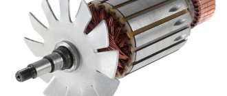
Testing an electric motor is a fairly simple process, however, it requires knowledge of some subtleties and attentiveness from the inspector. What knowledge will be needed when preparing for the call? What is a drive test using a multimeter? Let's find out below.
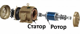
Single-phase motor device
Despite their name, single-phase motors have three coils in their design, and this is the minimum. Two of them are located in the stator and are connected in parallel. In this case, only one works directly, the second is called the launcher. The terminals of the working and starting windings are brought out to the body of the unit, with their help the drive is connected to the network. Two of them are connected to the network, all the rest perform switching functions. The rotor winding is made of a short-circuited type.
To be able to change the power of the device, the winding coil can be made of two parts. They will turn on sequentially.
You can determine the type of winding (working and starting) visually by paying attention to the cross-section of the wire and measuring the resistance using a tester. Let's talk in more detail about methods for determining the type of winding, how they differ and why they are needed in a single-phase motor.
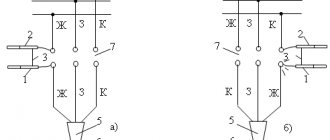
Winding diagram in a single-phase electric motor
Why do a single-phase motor have two windings?
All electric motors discussed today have low power. The magnetic core of a single-phase machine contains a winding of two phases, this is the main (working) and starting. The latter does not take part in the direct operation of the engine.
Such a pair of windings is needed to make the rotor of a single-phase motor rotate. The most popular of these drives are divided into two subtypes: electric motors with a starting winding and those that contain a run capacitor in their design.
In the first case, so to speak, the non-working winding will be turned on through the capacitor when the motor is started, and when the unit returns to normal operation (the rotation speed becomes constant), it will turn off by itself. The drive will continue to operate with one working winding. Information about the capacitor is usually indicated on a special plate on the motor housing. Its characteristics directly depend on the design.
Single-phase asynchronous motors containing a run capacitor always operate with the auxiliary winding switched on. It is turned on through this same capacitor. The capacity of such a capacitor also depends on its design features.
In other words, a motor with a starting winding is characterized by its turning off after starting. But with a capacitor auxiliary winding - its constant operation, because switching occurs through a constantly operating (even while the drive is running) capacitor.
To properly test the performance of a single-phase motor, knowledge of the design of its windings is critical. The differences between them can be found in the cross-sections of the wires, the number of turns, the resistance value of each of them (they can be measured with different types of testers or using an ohmmeter).
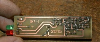
Multimeter selection criteria
Multimeters are used to test various electrical equipment. On sale you can find various versions of this measuring device, they all have their own characteristics. The main selection criteria are the following:
- Pointer or digital dial. Digital is more in demand today, as it has a large number of different functions and high accuracy. Today, switch models are practically not found on sale.
- Functionality. The more functions, the wider the scope of application of the device. This increases the cost of the measuring device.
- The backlight and hold button for readings can improve the comfort of using the multimeter.
- The lower the operating error, the more accurate the tester. Most models have an error of no more than 3%.
- If professional provision of services is envisaged, then attention should be paid to a model with a high degree of protection from dust or moisture. The higher the degree of protection of the device, the longer it will last.
- Electrical safety class. All measuring instruments are divided into 4 classes, which determine the scope of application of the multimeter.
You can check the basic indicators of an electric motor using the simplest equipment.
We learn to determine the starting and operating windings in single-phase asynchronous motors
Of course, having markings on the winding solves this problem. But often in case of repair or replacement of windings, it is not preserved. How then can you determine what kind of winding is in front of you? So we will discuss the theoretical and practical aspects of determining the starting and operating windings.
Inspect the product
For clarity, let’s take the engine that was installed in a washing machine during the USSR. The machine itself has been in scrap metal for a long time.
After a visual inspection of the nameplate on the engine, as in this case, you may not find it, but the age of the engine speaks for itself. In this case, all information can be found on the Internet. It turned out that the engine contains a starting winding and a relay start in its design.
Four wires are visible from the engine: two reddish, two bluish. These wires are also called winding leads.
Due to the absence of any markings, it is impossible to immediately determine which winding is the starting winding and which is the working winding. In such a situation, you need to pay attention to the cross-section of the conductors.
Section
Look at the wires that come out of the electric motor, or rather at their thickness. One of the pairs will be thinner. This is the starting winding. Therefore, the thicker pair is the working one.
It may happen that the cross-sections on both wires are the same, as in our situation. It is also impossible to visually determine where each winding is.
But if the difference in the thickness of the wires is noticeable, do not rely on the diameter alone. To determine the windings for sure, measure their resistance.
At this stage, we move on to measuring the resistance of the windings of a single-phase AC motor.
Final stage
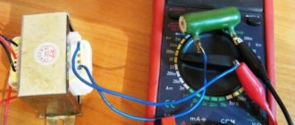
Resistance measurement
To measure the resistance of the windings of a single-phase motor, you will need a multimeter, on which you need to select continuity (or Ohm measurement mode).
We connect the wires protruding from the electric motor (any pair) to any leads of the multimeter and measure the value.
If you see number one on the screen, repeat the measurement with any other end.
Record the resistance shown by the first selected pair (in this case it turned out to be 16.5 ohms). After this, the probes of the measuring device need to be attached to the two remaining terminals (the second pair of wires) and measurements must be taken.
The data obtained also needs to be recorded and then compared with the first measurement.
The resistance of a serviceable working winding will always be less than that of the starting winding. The second pair of wires, according to the multimeter, showed a resistance of 34.5 ohms. Thus, we can safely say that the first pair of wires indicates that they belong to the working winding, and the second, accordingly, to the starting winding.
Label both windings so that you don't have to do it all over again in the future. It is convenient to use a small vinyl tube for this.
You can mark the ends of the wires (terminals) according to modern standards like this:
- the signs U1-U2 mark the working winding;
- signs B1-B2 mark the starting winding.
Such designations are placed in cases where four terminals are visible from the engine, in a given situation. However, you may come across a motor that has only three terminals. What to do?
So, the measurements for each of the three pins will look something like this: 10 ohms, 25 ohms and 15 ohms. Having completed these measurements, you need to immediately proceed to others. It is important to find a pin that, with the other two pins, will show 10 and 15 ohms. Congratulations! You are our network wire. The pin showing a resistance of 10 ohms is also a network pin, and the one that showed 15 ohms is a starting pin. It is connected to the second network through a capacitor. By the way, to change the direction of rotation in such a motor, you will have to get to the winding circuit itself.
Sometimes the measurements can be 10 ohms, 10 ohms and 20 ohms. This is the norm, such windings also exist, they were also installed on various household appliances. The peculiarity of such an engine is that which winding will be the starting one and which winding will be the working winding does not matter at all. They are the same. Just one of them (the one that will be the starting one) needs to be connected through a capacitor.
So we figured out simple methods for recognizing starting and working windings. Now you can distinguish the components of the engine even if there is no nameplate and any pin markings. We offer a little summary of all the information:
- In the case where the motor has four terminals, you only need to find the ends of the windings, which are easy to disassemble after measuring. The wire where the resistance value is lower is the working winding, and the higher is the starting winding. Connecting all the terminals is very simple: 220 V voltage is supplied to those wires that are thicker. And one of the ends of the starting wires is on one of the working ones. At the same time, it does not matter at all what exactly the tip of the working winding output is on, because the direction of rotation does not depend on this in any way (as well as, say, on which side you insert the plug into the socket). The rotation only changes depending on which end of the starting winding you connect.
- If there are only three wires as the output of the windings, the network wire will be the one that shows the least resistance, as well as the one that, when connected to the other two, will show a resistance of 10 Ohms and 15 Ohms (if the resistance measurements of each of them gave 10 Ohms, 25 Ohms and 15 Ohm). The one that showed 15 Ohms on the multimeter is the output of the starting winding.
- If you come across a three-wire output, and the resistance of each wire (as an example) is 10 Ohms, 10 Ohms and 20 Ohms, both windings can be working and starting.
To identify electric drive breakdowns at home, it is enough to use a multimeter. Firstly, not everyone has expensive professional equipment (this is rather an exception), and secondly, this device is, as they say, sufficient to identify most faults. You don't need any specialist here.
The most basic malfunction in single-phase motors is stopping rotation. The cause of such a breakdown is determined quite simply. The multimeter is switched to voltmeter mode and the voltage supply that powers the engine is checked. If everything is in order with the voltage, then the fault lies in the engine itself, its electrical part. This, of course, indicates the need to check the connection status and ringing of the windings. For this, a multimeter is often also used.
But how to properly prepare for the engine ringing?
How to check resistance: winding data measurement, repair
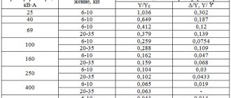
When preparing to work with a different voltage, the windings are counted. It is important to take into account that the number of conductors increases proportionally. If you need to work with twice the voltage, then the number also doubles. The same thing happens with rewinding under reduced power supply, only with the opposite sign, i.e. the number of conductors is halved.
If the structure contains a large number of conductors, then rounding the result is acceptable. An odd number of conductors implies multi-turn coils - this aspect concerns double-layer winding. In single-layer rewinding, the quantity can be fractional.
Important : A slight increase in the fill factor is allowed, but when the parameter exceeds the permissible characteristic several times, a number of measures must be taken: reduce the thickness of the insulating layer (the same applies to the wedge), choose a wire with a low insulation thickness. It is possible to reduce the diameter of the copper wire, but the power of the equipment will decrease.
Replacing the winding conductor (OP)
A change in resistance with a large deviation from the nominal parameters is a reason to carry out diagnostic measures; the winding may be faulty. Instead of a winding conductor, two other wires can be used if the sum of their cross-sections is equal to or greater than OP.
The range of choices increases by changing the type of phase connection (relevant for three-phase). During switching, the current increases, therefore, it is necessary to increase the cross section until the increase is equal to the current. But the number of effective conductors (EC) decreases in number, identical to the increase in current. Changing the circuit reduces the voltage.
Brushless Equipment Repair
Restoring the functionality of such equipment is a complex set of measures, which involves performing in-depth diagnostics, replacing faulty stator and rotor windings, adjusting the location of shafts, replacing worn bearings, and turning slip rings. This also includes metalwork and painting.
Stages:
- familiarization with the characteristics of the device, including nominal information from the manufacturer - power, voltage, current, rotor speed;
- external inspection, preliminary check of equipment. Detailed inspection of the external part, bearing assemblies, connecting terminals. Specialized stands and megohmmeters are used. The primary stage is measuring insulation resistance, checking electrical equipment, breakdown testing, thorough testing to detect burnt out and short-circuited turns;
- complete disassembly - carried out according to the diagram;
- work with bearings - checking, pressing. Equipment – press, professional pullers (handicraft ones are not allowed as they can damage the surface of the shafts), mandrel. Here the running of the bearings is checked;
- dismantling the windings - additionally checking the resistance. Elements can be exposed to an electric furnace - determining the heating of the windings.
External examination is an important diagnostic nuance that requires a lot of time. The first elements that you should immediately pay attention to are the terminal and termination boxes. They contain external violations of the insulating layer. The distance between the parts responsible for the flow of current is measured - it must be significant, otherwise overlap on the surface will occur.
The air gap is to ensure the characteristics of the device. It should be sufficient and not differ over all surfaces by more than 10%, taking into account the nominal value.
Specialized washing - a solution is required that removes residues of work products and technical processes on the surface of the device. Thorough check for defects (arising in production, resulting from rapid and poor quality maintenance).
Resistance measurement
Determining the parameter of DC motors is an important part of diagnostics and further maintenance of equipment. Based on the results obtained, a conclusion is drawn about the performance and current state of the equipment. Resistance values are indicators that determine the state of the connection and indicate breakdowns.
The diagnostic operation is performed in several ways: with an ammeter, voltmeter, electric bridge, microohmmeter. The resistance of the OF and equalizing winding is insignificant, and therefore it is advisable to use a microohmmeter or a double bridge here.
Armature resistance is a parameter determined by an ammeter (voltmeter). Contact probes are used to probe certain areas of the copper rewind. The measurement goes like this:
- Current is supplied to the collector plates - to each in turn. First you need to dismantle the anchor and remove the brushes. A similar action is carried out with all plates;
- the data obtained should not differ significantly from the nominal values; if the error is large, then the part is faulty.
Measurement of parameters in dimensional devices is carried out with extreme caution - they use professional diagnostic equipment designed for the assigned tasks, for example, an ammeter and voltmeter, a double bridge. Equipment where there are three stator winding terminals, the resistance is calculated in pairs.
In diagnostic operations, one of the key roles is played by determining the temperature regime. Appropriate indicators and thermometers that are well calibrated for measurements help with this. The operations carried out by an ammeter and a voltmeter are repeated for different current parameters. To measure with bridges, you need to vary the balance of the bridge - the data obtained should not differ from the average resistance by a large factor.
Important : The serviceability of the windings is determined by the passage of rated currents through them, which form the magnetic field fluxes. Damage to the rewind is characterized by a violation of the insulating layer, which leads to leakage currents, short circuits and interturn circuits. All this has an extremely negative impact on the operational properties of the equipment.
Checking the rewinding of the stationary part
The stator, which has three phases, is equipped with three windings and six output wires. Atypical designs may have three or four terminals, typical for arranging connections inside the case.
The fault is determined by checking with an ohmmeter (select the appropriate multimeter mode). One probe is placed on an arbitrary pin, and the second probe alternately measures the active resistance. A copper pair with readings in Ohms is one winding (in order not to forget, it is better to mark it with any marking). You need to do the same with all other conductors.
Winding is done using the same wire throughout the entire process. Therefore, the turns create equal inductive reactance. In the event of a break or damage, a difference between active and total resistance is created - a consequence of an interturn short circuit.
Advice : To prevent transition resistance from disturbing the measurement process, a circuit with a metrological device (voltmeter) should be connected to the slip rings using specialized parts - brushes. Separate connection is made with double probes. You need to use the ammeter and voltmeter several times - this will allow you to determine the average value at different voltages.
Preparatory stage of verification
Short the multimeter probes
Before performing diagnostics, you must perform the following steps:
- Disconnect the machine from power. If the winding resistance is measured with the circuit connected to the mains, the unit will break down.
- Close the multimeter probes and set the values to zero. This is called calibrating the device.
- Inspect the engine carefully. It could be flooded, some parts could break off, and there might be a burning smell. In this case, there is no point in calling the unit, because the breakdown is obvious.
Asynchronous, single-phase and three-phase, commutator - all motors ring in the same way. The methodology does not differ depending on the difference in the design of the units, since all the differences are so fundamental. However, there are some details in the diagnosis that cannot be ignored.
How to determine the integrity of the stator without disassembling the hammer drill
To determine the integrity of the stator, you need to ring its windings, measure the winding resistance and insulation resistance.
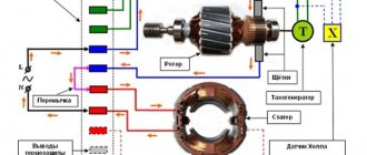
Stator and rotor continuity diagram
To measure the winding resistance of a Makita hammer drill, you need to connect one end of the tester to the freed brush holder, and the other to one of the ends of the electric plug. If the device does not show anything, change the other end of the plug. If the resistance is infinity, there is a break in the stator and it requires replacement or repair. Don’t forget, you can’t do without a circuit diagram of a Makita 2450,2470 rotary hammer.
Simple connection diagram for a commutator motor
If some kind of resistance is shown, it is important to measure its exact value. As a rule, the resistance of the stator winding of the Makita-2450 hammer drill at a temperature of +20ºС lies within 25 Ohms
Directly checking the engine with a multimeter
The most common breakdowns are divided into two main groups:
- there is contact where it should not be;
- there is no contact where it should be.
Let's look at how to ring a single-phase AC electric motor using a multimeter. It has two coils, one of which is working and the second is auxiliary. The level of reliability of contacts, the quality of insulation and the correctness of winding have a huge influence on the level of engine performance.
- The first thing to do is check for a short to body. Here you need to remember that all values on the multimeter will be approximate. To obtain accurate data, more expensive and accurate measurement devices will be needed.
- The measurement values on the device are set to maximum.
- The probes are connected to each other. This way you can make sure that the multimeter itself is working and configured correctly.
- Then one probe is connected to the drive housing. If there is contact, you can also connect a second probe. Track your readings.
- If nothing goes wrong, touch the phase output with the probe.
- With high-quality insulation, the device will show a high resistance value. It can be within even several thousand megaohms.
Remember that when measuring insulation resistance with a multimeter you will always get high readings (above acceptable standards). This is due to the fact that the electromotive force of the device is a maximum of 9 V, and the engine, as we know, performs work with a voltage of 220 V or even 380 V. Ohm’s law says that the amount of resistance depends on the amount of voltage, so you should always make allowance for the difference .
It is also mandatory to check the integrity of the windings. It is necessary to ring all the ends that enter the terminal box of the unit. If there is a break, then it is better to stop the test, because there is no logic in further diagnostics. You need to work on solving this problem first.
Knowing the rules and procedure for ringing a single-phase motor using a multimeter, you can easily save on diagnostics and repairs when the motor actually has only minor breakdowns. But if you realize that everything is not so simple or simply do not understand what is wrong with your electric motor, it is better to take it to a professional who will conduct a more detailed check with expensive and sensitive instruments.
To identify and repair a problem with a brushed motor, it will most likely have to be disassembled.
Checking asynchronous engines
It is asynchronous motors that are most often used in household units that operate on 220 V. After removing the motor from the equipment, you need to measure the resistance between the motor terminals:
- Select resistance measurement function and range up to 100 ohms.
- Connect the lugs to the terminals of the connected winding. Between the middle and the extreme, the normal value is 30-50 Ohms, between the middle and the other extreme 15-20.
It is also important to check for current leakage:
- Select the resistance measurement function with a range of 2000 kOhm.
- Connect each terminal in turn to the motor body.
- There should be no values on the display. If you are using an analog multimeter, the needle does not deviate.
If problems are identified, you will have to disassemble the device to conduct more thorough investigations. An interturn short circuit often occurs. To identify them, a range of 100 Ohms is selected, after which each stator circuit is called. A strong deviation of one reading from another indicates a short circuit in the winding.
Video on how to test a motor with a multimeter:
Frequent malfunctions
Before disassembling, be sure to look for sparking, which usually occurs in the contact-brush mechanism. If you notice an increased level of sparking, it is worth checking the contact of the brushes or the presence of an interturn short circuit in the commutator itself.
As a rule, the main reasons why commutator motors break down are severely worn brushes or a blackened commutator. Old brushes are usually replaced with new ones. They must be the same in size and shape. It is best to install original parts (from the same manufacturer as the engine). Changing them is quite simple: remove (move) the lock or unscrew the bolt. Some engine models may require changing not only brushes, but also brush holders. Don't forget to connect the copper lead to the contact.
If the brushes are normal, check the springs that press them by stretching them.
If the contact part of the commutator becomes dark, clean it using fine sandpaper. It is also called zero.
At times, a groove forms at the point where the brushes and commutator come into contact. It needs to be sharpened using a machine.
Single-phase brushed motor
Another common failure of a commutator single-phase motor is bearing wear. If the housing vibrates strongly during operation and the bearings break, they definitely need to be replaced. If you start the situation, the mentioned parts will touch the rotor and stator, which may lead to their inevitable replacement. This is already more difficult and more expensive.
Design features
The design of electric motors can differ significantly, but it is often represented by a combination of similar elements. The moving element is usually called the rotor, the stationary element is called the starter. Copper wire can be wound as follows:
- The coil is only on the rotor.
- The coil is only on the starter.
- Winding on moving and stationary parts.
Rare malfunctions
Breaks and burnouts of windings and connection points occur much less frequently in commutator motors. It is also rare to see melting and shorting of the lamella with graphite dust.
To avoid such breakdowns, during an external inspection you should always pay attention to:
- integrity of windings;
- presence of blackening on the windings;
- the strength of contact between the collector lamellas and the wire leads. If necessary, they need to be re-soldered;
- the amount of graphite dust between the collector lamellas. Be sure to remove dust if necessary;
- presence of a burning smell (this may be insulation).
During a visual inspection, did you find that the stator/rotor winding is damaged? Rewind it or simply replace it with a new one.
Unfortunately, damage to the winding cannot always be seen with the naked eye, so if there are no obvious breakdowns, check them with a multimeter.
Checking the capacitor with a multimeter
Of course, the most reliable way to test a faulty single-phase motor with a capacitor is to use an ohmmeter to measure the resistance value. The device will accurately show the resistance of the capacitor, and from this it is already possible to draw conclusions about how integral the dielectric is, on which the serviceability of the electronic device directly depends.
In everyday life, when no one requires exact values from you, and you only need to find out the cause of the breakdown, a multimeter will be enough.
The verification algorithm is as follows:
- the multimeter switches to Ohm measurement mode;
- then you need to set the upper resistance value - infinity;
- measure the resistance of the capacitor at the terminals.
If the resistance is low (and this is any value other than infinity), then the device that passes the test is broken. Here either the dielectric is broken or the electrolyte has leaked.
Does the dial needle on the tester show a slight deviation and then return to its original position? The capacitor is working properly and is slowly gaining capacity.
A device needle that deviates and then fixes on one of the values also indicates a breakdown of the electronic device.
As we have already found out, a multimeter is an indispensable device for quickly and multidisciplinary checking engines for serviceability. It can be found in all specialized craftsmen and in many home workshops. With its help, you can identify the main types of breakdowns of electrical appliances, and engines are no exception.
The most common breakdowns in electric motors and other machines of this type are the following:
- broken winding on the rotor or stator;
- presence of a short circuit;
- the presence of an interturn short circuit.
Each issue on the list above deserves a closer look.
Causes of interturn short circuit in the rotor
There are several reasons why the wiring on the rotor turns may short out. Among them:
- overheating due to high loads;
- mechanical damage to the winding;
- moisture ingress.
Exceeding the load on the electric motor and subsequent overheating with a short circuit can occur due to improper operation of the equipment by the operator. The load on the mechanism, which is indicated in the technical documentation, must not be exceeded. Therefore, you should always carefully read the instructions for electrical household devices. This also happens at industrial enterprises, but there workers undergo training before they are allowed to work with machines and other electric-powered mechanisms.
Another reason for excess load may be damage to the armature bearings. They can jam due to manufacturing defects, wear, or lack of lubrication. This will significantly complicate rotation and lead to critical overloads. In addition, dirt or solid debris, such as metal shavings, that have gotten into the housing can prevent the rotor from rotating. As well as fragments of a broken part inside the engine. They can not only slow down the rotor, but also damage the winding insulation, which will also lead to an interturn short circuit.
Getting water inside the engine is dangerous in itself, as it is an excellent conductor that can lead to a short circuit. But even if this does not happen, high humidity will cause corrosion, which will prevent the rotor from rotating. And this, as discussed above, leads to overheating due to increased loads and short circuiting of the wires.
You can understand that the rotor coil turns have short-circuited by the unstable operation of the engine, sparking of the brushes and uneven heating of the housing. There is also a decrease in power and sudden voltage surges when a device with a closed rotor is connected to the network. This can be understood by the blinking light in the light bulb. There may be a smell of burnt insulation.
Even if there is the slightest doubt, it is necessary to check the rotor for short circuit. Otherwise, this may lead to more serious damage to both the engine and the entire mechanism or machine. One shorted section will lead to overheating, disruption of the insulation of adjacent turns and to a more extensive short circuit. Therefore, a motor with an interturn short circuit on the rotor will not work for a long time.
The winding has broken
There is nothing surprising about a winding break; this is the most common malfunction in the operation of electric drives. A breakdown can occur in both the stator and the armature.
If one phase in the winding breaks, then there will be no current in this place, but in the second phase the current indicator will be overestimated. This can be measured using the same multimeter in ammeter mode.
In general, this failure is equivalent to a loss of phase. For example, if a break suddenly occurred while the drive was in operation, the engine begins to sharply lose power and overheat. If the protection on the unit is working correctly, it will turn off. Solving the problem basically requires rewinding.
In a situation where a break has occurred in the rotor, the frequency of current oscillation will be equal to the frequency of voltage oscillation and slip. External signs: strong buzzing and vibration, decreased drive speed.
All these are just causes of breakdowns, but they can only be detected if you ring each winding of the electric motor and measure their resistance.
The starting and working windings are connected in those single-phase motors that operate at an alternating voltage of 220 V. The starting winding must produce a resistance that is 150% greater than that of the working winding.
To quickly check the performance of the electric motor, you can also use a function on the multimeter called “Dialing”. If the circuit is working properly, you will hear the characteristic sound of the device, and in some models there is also a light indicator. But if there is a break in the circuit, you will not hear any sound.
Which electric motors can be checked with a multimeter?
If there is no mechanical damage in the engine, which is usually determined visually, then its malfunction in most cases is due to the following:
- there is a break in the internal circuit;
- a short circuit has occurred, that is, contact has appeared where there should not be one.
Both defects are detected with a multimeter. Difficulties arise only when checking DC motors: most of them have a winding with almost zero resistance and it has to be measured using an indirect method, for which you will need to assemble a simple circuit.
- Three-phase asynchronous motors also operate with single-phase power.
- Asynchronous single- and two-phase capacitors with squirrel-cage rotor. Most household appliance motors belong to this type.
- Asynchronous with wound rotor. Such a rotor has a three-phase winding. Motors with a wound rotor are used where it is necessary to regulate the rotation speed and reduce the starting current: in crane equipment, machine tools, etc.
- Collector. Used in hand-held power tools.
- Asynchronous three-phase with squirrel-cage rotor.
The popularity of motors of the latter type is explained by a number of advantages:
- simplicity of design;
- strength;
- reliability;
- low cost;
- unpretentiousness (does not require maintenance).
Checking for short circuit
One of the common failures in electric motors is a short circuit to the frame. To find this kind of breakdown with a multimeter, do the following:
- set the resistance measurement of the device to maximum;
- check the serviceability of the multimeter itself by connecting its probes to each other;
- Connect one of the probes to the engine body;
- Connect the remaining one in turn to each of the phases.
If the engine you tested is working properly, then the resistance will show hundreds and even thousands of megaohms.
It is even easier to investigate for a short circuit in the “Dialing” mode. You need to do the same steps, and if you hear a sound (as when the winding is being tested), this will indicate the presence of violations in the integrity of the winding insulation, as well as the presence of a short circuit to the housing.
It should be noted that a breakdown of this type not only has a negative impact on the engine itself, but is dangerous for the lives of people working with the machine (if the necessary protective equipment is not available).
Collector design
Collector models have also become very widespread. Their design features differ significantly when compared with asynchronous models. Checking the functionality when using a multimeter is carried out as follows:
- The tester is set to detect Ohm. The test begins with measuring the resistance on the collector lamellas. It is worth considering that normally the data obtained should not differ significantly.
- Next, the resistance indicator is measured, for which one probe of the device is applied to the armature body, the other to the commutator. The resulting resistance value should be high, approaching infinity. This indicates that the insulation is in good condition.
- The next step involves determining the stator for winding integrity. To do this, one probe is applied to the stator housing, and the other to the terminals. The higher the score, the better.
When using a multimeter, it will not be possible to check the turn-to-turn short circuit. A special apparatus is used for this.
Reasons for low resistance
Under normal conditions, the insulation resistance of motor wires covered with a protective film remains unchanged for a long time. But during operation it is affected by a number of destructive factors, the main of which are:
- Mechanical stress.
- Increased environmental humidity.
- Exposure to aggressive substances contained in it.
- Sudden temperature fluctuations.
Additional information: Overheating of an engine operating in abnormal mode also has a significant impact on the condition of the containment shell.
All of these factors lead to a decrease in insulation resistance with the possibility of subsequent breakdown of the winding to the housing or an interphase short circuit.
Please click on one of the buttons to find out if the article helped or not.