Cable line tests are carried out at the following intervals:
- annually - for power supply and distribution lines with rubber insulation, serving life support facilities of populated areas and other important consumers;
- every 3 years - for main supply lines 6–35 kV;
- every 5 years - for backup lines.
- Extraordinary - in case of emergency shutdown of electrical equipment.
Cable testing with increased voltage is carried out to assess the compliance of the resistance value, absorption coefficient and other parameters of the insulating sheath with established standards. During testing, defects are identified that can provoke an accident and failure of expensive electrical equipment.
Test methods.
1. Checking the integrity and phasing of the cable cores.
Determination of the integrity of the cores and phasing of cable lines is carried out after completion of installation, reinstallation of couplings or disconnection of cable cores during operation.
Determination of the integrity of cable cores with voltages up to 10 kV is carried out using a megaohmmeter. After switching on the CL, the correct phasing is checked.
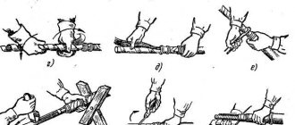
The essence of energized phasing is to determine the correspondence of the cable phase, which is energized from the switchgear at the opposite end of the cable, to the supposed phase of the same name of the switchgear buses where phasing is performed. For phasing 6 and 10 kV cable lines under voltage, 10 kV voltage indicators are used, complete with additional resistance, Figure No. 1. The integrity and coincidence of the phase designations of the connected cable cores must correspond.
Rice. No. 1 Phasing of live cable lines.
a – correspondence of cable and bus phases; b – different phases of buses and cables at the connection point of the latter; 1 – voltage indicator; 2 – resistance tube; 3 – wire; 4 – tire; 5 – end seal; 6 – cable; 7 – tire deflation connector.
Insulation resistance measurement.
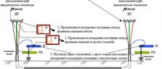
Measurement of insulation resistance of high-voltage cables is carried out on a completely disconnected cable.
Before checking, it is necessary to check the reliability of the grounding of the cable funnels, armor and connect them to a portable grounding with special clamps (crocodiles). The second end of the cable remains free; the cores must be separated at a sufficient distance (approximately 150 - 200 mm).
If it is impossible to ensure the required distance between the cores and cable cores to grounded parts of the equipment, insulating caps or covers are put on the cores.
Before starting measurements, you must make sure that there is no
voltage, thoroughly clean the insulation from dust. Measurements should be made with the instrument needle in a stable position; To do this, you need to quickly but evenly rotate the generator handle (120 rpm) for 60 seconds. The insulation resistance is determined by the needle reading on the megohmmeter. To connect a megohmmeter to the device or line being tested, separate wires with a high insulation resistance (at least 100 mOhm) should be used.
A megohmmeter measures the resistance of the conductors one by one, and a portable grounding is installed on the conductors free from measurement. The circuit for measuring the insulation resistance of power cable lines is shown in Figure No. 2
Rice. No. 2 Scheme for measuring the insulation resistance of a power cable.
Measuring the insulation resistance of power and control cables with voltages up to 1000V is carried out in the same way, with measurements being made between every two wires (between phases, between phase conductors and zero, between phase conductors and a protective conductor, and between a neutral and protective conductor). When measuring, it is allowed to combine the neutral working and neutral protective conductors. For four-core cables, the insulation resistance of the neutral conductor is measured relative to grounded parts of electrical equipment.
Before the first or repeated measurements, the CL must be discharged by connecting all metal elements to each other and the ground for at least 2 minutes. The insulation resistance of cables up to 1 kV must be at least 0.5 MOhm. For power cables above 1 kV, the insulation resistance is not standardized. The measurement should be made before and after testing the cable with increased voltage.
Selection of test voltage
| Operating voltage of cable/equipment | DC test voltage |
| 24 to 50 V | 50 to 100 VDC |
| 50 to 100 V | 100 to 250 VDC |
| 100 to 240 V | 250 to 500 V DC |
| 440 to 550 V | 500 to 1000 V DC |
| 2400 V | 1000 to 2500 V DC |
| 4100 V | 1000 to 5000 V DC |
| From 5000 to 12,000 V | 2500 to 5000 V DC |
| > 12,000 V | 5000 to 10,000 VDC |
The table above shows the recommended test voltages according to the operating voltages of installations and equipment (values taken from IEEE Guide 43-2000).
In addition, these values are specified for electrical appliances in a wide variety of local and international standards (IEC 60204, IEC 60439, IEC 60598, etc.).
In France, for example, the NFC15-100 standard provides test voltage and minimum insulation resistance values for electrical installations (500 V DC and 0.5 MΩ for rated voltages from 50 to 500 V).
However, you are strongly advised to contact the cable/equipment manufacturer for their own recommendations on the required test voltage.
Test with increased voltage of rectified current.
Testing the insulation of cable lines with increased voltage of rectified current is carried out in order to identify local concentrated defects that are not detected when measured with a megohmmeter, by bringing them to breakdown during the test. Such a test with increased voltage of rectified current is carried out from a special installation such as: AID-70, SKAT-70, etc.
The voltage from the installation is applied in turn to each phase of the cable, while grounding the other two phases and the cable sheath (similar to measuring insulation with a megohmmeter). The circuit for testing the cable with increased voltage of rectified current is shown in Figure No. 3.
Rice. No. 3 Testing the cable with increased rectified voltage.
Insulation of single-core cables without metal screen (sheath, armor),
laid in air are not tested. The insulation of single-core cables with a metal screen (sheath, armor) is tested between the core and the screen. The insulation of multi-core cables without a metal screen (sheath, armor) is tested between each core and the remaining cores connected to each other and the ground.
The insulation of multi-core cables with a common metal screen (sheath, armor) is tested between each core and the remaining cores connected to each other and the screen (sheath, armor). For all of the above types of tests, metal screens (shells, armor) must be grounded. Plastic sheaths (hoses) of cables laid in the ground are tested between screens (sheaths) disconnected from the ground and the ground. Plastic sheaths (hoses) of cables laid in air are not tested. The test voltage value is taken in accordance with table No. 2
Test voltage kV, for power cables.
Table No. 2
| Type of test | Test voltage (kV) for cable lines | ||
| Paper insulated cables | |||
| Up to 1kV | 6kV | 10kV | |
| P | 6 | 36 | 60 |
| TO | 2,5 | 36 | 60 |
| M | — | 36 | 60 |
| Type of test | Plastic insulated cables | ||
| Up to 1kV* | 6kV | 10kV | |
| P | 3,5 | 36 | 60 |
| TO | — | 36 | 60 |
| M | — | 36 | 60 |
| Type of test | Rubber insulated cables | ||
| Up to 3kV | 6kV | 10kV | |
| P | 6 | 12 | 20 |
| TO | 6 | 12 | 20 |
| M | 6** | 12** | 20** |
* - high voltage testing of single-core cables with plastic insulation without armor (screens) laid in the air is not carried out.
** - after repairs not related to cable reinstallation, the insulation is checked with a megohmmeter for a voltage of 2500V, and testing with increased rectified voltage is not performed.
For cables for voltages up to 10 kV with paper and plastic insulation, the duration of application of the full test voltage during acceptance tests is 10 minutes, in operation 5 minutes. For cables with rubber insulation for voltage 6-10 kV, the duration of application of the full test voltage is 5 minutes.
Permissible leakage currents depending on the test voltage and permissible values of the asymmetry coefficient when measuring leakage current are given in Table No. 3. The absolute value of the leakage current is not a rejection indicator. Cable lines with satisfactory insulation must have stable leakage current values. During testing, the leakage current should decrease. If there is no decrease in the leakage current, or if it increases or becomes unstable, the test is carried out until the defect is identified, but not more than 15 minutes.
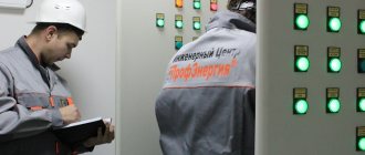
Topic 2. Electrical tests
Electrical tests of devices and systems are carried out to check the electrical strength, insulation resistance and normal functioning of the aircraft. Electrical tests include: autonomous tests of devices, assemblies and systems before installation on the device, tests during the assembly process; comprehensive testing of undocked and docked aircraft. Electrical strength and insulation resistance are checked on assembled blocks or systems:
— between electrical circuits and metal insulated parts of devices;
— between electrical circuits that are disconnected during operation;
- between electrically unconnected circuits.
First, the electrical strength is checked, and then the electrical insulation resistance is measured. The scope of electrical tests is determined by the NTD.
2.1. Electrical strength test
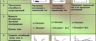
Electrical strength is the ability of electrical insulation to withstand the action of electrical voltage applied to it. It is determined by the voltage value at which breakdown occurs - breakdown voltage.
Electrical strength can be determined using the formula
where is the field inhomogeneity coefficient; - voltage causing breakdown; — insulation thickness.
Breakdown voltage depends on surface roughness, presence of oil, moisture, dust, hygroscopicity, etc. The rated voltage applied to the product insulation during normal operation is less than the breakdown voltage. The test voltage for checking the electrical strength of insulation depends on the rated voltage, its power, operating modes and is determined by the normative and technical documentation.
During testing, it is allowed to combine several electrically independent circuits having the same operating voltage into a single system.
The test voltage is calculated using the formula
where is the voltage determined by the technical documentation; - coefficient; - Rated voltage. The test voltage must be sinusoidal. In practice, the insulation is subjected to a maximum voltage with an amplitude of .
With a peak voltage at the same effective value, the amplitude is much greater.
The test voltage should increase and decrease smoothly. When the voltage is suddenly turned on or off in the circuit under study, which has significant inductance, shock overvoltages may occur; the shock field strength at the moment of the pulse will be greater than the electrical strength of the insulation, and then a breakdown will occur. The duration of the test voltage change to must be more than 10 s. It is possible to change the voltage in steps from 0 to 0.5, then in steps of (0.05 - 0.10) increase to the maximum voltage, hold for 1 minute and step down the voltage.
Installations for testing electrical insulation strength usually have a power of more than 500VA, so only specialists who have undergone special safety training are allowed to operate.
The insulation of aircraft having different conductivities in different directions is subjected to direct current voltage testing.
The electrical strength of the interturn insulation of the windings of electrical machines is checked at idle by gradually increasing the voltage on the winding. The insulation must withstand a voltage of 1.5-2 times the operating voltage for 5 minutes. The breakdown of the interturn winding insulation is monitored by reducing the voltage.
When checking the electrical strength of products under reduced pressure conditions, tests are carried out in a pressure chamber at test pressure.
2.2. Insulation resistance test
Under the influence of applied voltage, electrical insulating materials exhibit electrical conductivity. The electrical conductivity of dielectrics is much lower than that of conductors, and at the same time this characteristic of dielectrics plays an important role in the functioning of equipment. The leakage current of a dielectric has two components: the current passing along its surface and the current passing through the dielectrics. The ratio of the voltage applied to the dielectric to the leakage current is called the insulation resistance. Insulation resistance can be determined by the relation
where is the leakage current along the insulation surface; — leakage current through the insulation layer.
Insulation resistance depends on mechanical influences, temperature, penetrating radiation, state of the dielectric surface, quality of processing, assembly, impregnation, etc.
Insulation resistance is checked, as a rule, in normal climatic conditions after exposure to mechanical and climatic factors.
The lower limit of the insulation resistance should be:
— in a cold dry state ≥20 Mohm;
— in a heated state ≥2 Mohm;
— in a humidified state, at least 1 Mohm;
In some cases, a lower insulation resistance limit may be set.
Insulation resistance is checked in the following ways:
— network and manual megaohmmeters,
- using a voltmeter with a certain internal resistance.
The insulation resistance of the input of the measuring instruments must exceed the measured insulation resistance by an order of magnitude. The measuring voltage must match the operating voltage of the circuit being measured. Registration of insulation resistance values is carried out, as a rule, one minute after applying the measuring voltage.
To measure insulation resistance, magnetoelectric megohmmeters and megohmmeters using electronic autocompensation circuits are most often used.
Electrical tests of devices and systems are carried out to check the electrical strength, insulation resistance and normal functioning of the aircraft. Electrical tests include: autonomous tests of devices, assemblies and systems before installation on the device, tests during the assembly process; comprehensive testing of undocked and docked aircraft. Electrical strength and insulation resistance are checked on assembled blocks or systems:
— between electrical circuits and metal insulated parts of devices;
— between electrical circuits that are disconnected during operation;
- between electrically unconnected circuits.
First, the electrical strength is checked, and then the electrical insulation resistance is measured. The scope of electrical tests is determined by the NTD.
2.1. Electrical strength test
Electrical strength is the ability of electrical insulation to withstand the action of electrical voltage applied to it. It is determined by the voltage value at which breakdown occurs - breakdown voltage.
Electrical strength can be determined using the formula
where is the field inhomogeneity coefficient; - voltage causing breakdown; — insulation thickness.
Breakdown voltage depends on surface roughness, presence of oil, moisture, dust, hygroscopicity, etc. The rated voltage applied to the product insulation during normal operation is less than the breakdown voltage. The test voltage for checking the electrical strength of insulation depends on the rated voltage, its power, operating modes and is determined by the normative and technical documentation.
During testing, it is allowed to combine several electrically independent circuits having the same operating voltage into a single system.
The test voltage is calculated using the formula
where is the voltage determined by the technical documentation; - coefficient; - Rated voltage. The test voltage must be sinusoidal. In practice, the insulation is subjected to a maximum voltage with an amplitude of .
With a peak voltage at the same effective value, the amplitude is much greater.
The test voltage should increase and decrease smoothly. When the voltage is suddenly turned on or off in the circuit under study, which has significant inductance, shock overvoltages may occur; the shock field strength at the moment of the pulse will be greater than the electrical strength of the insulation, and then a breakdown will occur. The duration of the test voltage change to must be more than 10 s. It is possible to change the voltage in steps from 0 to 0.5, then in steps of (0.05 - 0.10) increase to the maximum voltage, hold for 1 minute and step down the voltage.
Installations for testing electrical insulation strength usually have a power of more than 500VA, so only specialists who have undergone special safety training are allowed to operate.
The insulation of aircraft having different conductivities in different directions is subjected to direct current voltage testing.
The electrical strength of the interturn insulation of the windings of electrical machines is checked at idle by gradually increasing the voltage on the winding. The insulation must withstand a voltage of 1.5-2 times the operating voltage for 5 minutes. The breakdown of the interturn winding insulation is monitored by reducing the voltage.
When checking the electrical strength of products under reduced pressure conditions, tests are carried out in a pressure chamber at test pressure.
2.2. Insulation resistance test
Under the influence of applied voltage, electrical insulating materials exhibit electrical conductivity. The electrical conductivity of dielectrics is much lower than that of conductors, and at the same time this characteristic of dielectrics plays an important role in the functioning of equipment. The leakage current of a dielectric has two components: the current passing along its surface and the current passing through the dielectrics. The ratio of the voltage applied to the dielectric to the leakage current is called the insulation resistance. Insulation resistance can be determined by the relation
where is the leakage current along the insulation surface; — leakage current through the insulation layer.
Insulation resistance depends on mechanical influences, temperature, penetrating radiation, state of the dielectric surface, quality of processing, assembly, impregnation, etc.
Insulation resistance is checked, as a rule, in normal climatic conditions after exposure to mechanical and climatic factors.
The lower limit of the insulation resistance should be:
— in a cold dry state ≥20 Mohm;
— in a heated state ≥2 Mohm;
— in a humidified state, at least 1 Mohm;
In some cases, a lower insulation resistance limit may be set.
Insulation resistance is checked in the following ways:
— network and manual megaohmmeters,
- using a voltmeter with a certain internal resistance.
The insulation resistance of the input of the measuring instruments must exceed the measured insulation resistance by an order of magnitude. The measuring voltage must match the operating voltage of the circuit being measured. Registration of insulation resistance values is carried out, as a rule, one minute after applying the measuring voltage.
To measure insulation resistance, magnetoelectric megohmmeters and megohmmeters using electronic autocompensation circuits are most often used.
Permissible leakage currents and asymmetry coefficient values for power cables.
Table No. 3
| Cable voltage (kV) | Test voltage (kV) | Permissible values of leakage currents (mA) | Acceptable values of coefficient. asymmetry |
| 6 | 36 | 0,2 | 8 |
| 10 | 45 | 0,3 | 8 |
| 50 | 0,5 | 8 | |
| 60 | 0,5 | 8 |
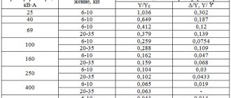
It is allowed to the technical manager of the enterprise during operation (M), based on local conditions, as an exception, to reduce the test voltage level for cable lines with a voltage of 6-10 kV to 0.4 Un.
Frequency of testing during operation.
Cables with voltage 2-35kV:
a) once a year - for cable lines during the first 2 years after commissioning, and thereafter:
- Once every 2 years - for cable lines for which during the first 2 years there were no emergency breakdowns or breakdowns during preventive tests, 1 time per year for cable lines on the routes of which construction and repair work was carried out and on which emergency breakdowns systematically occur isolation;
- 1 time every 3 years - for cable lines in closed areas (substations, factories, etc.); during major repairs of equipment for cable lines connected to units, 6-10 kV cable jumpers between busbars and transformers in TP and RP ;
b) It is permissible not to carry out the test:
- For cable lines up to 100 meters long, which are outputs from switchgear and transformer substations to overhead lines and consisting of two parallel cables;
- For cable lines with a service life of more than 15 years, on which the specific number of failures due to electrical breakdown is 30 or more failures per 100 kilometers per year;
- For cable lines subject to reconstruction or decommissioning in the next 5 years;
c) It is allowed by order of the technical manager of the enterprise to establish
other values of test frequency and test voltages:
- For supply cable lines for voltage 6-10 kV with a service life of more than 15 years with a number of connecting couplings of more than 10 per 1 kilometer of length;
- For supply cable lines with a voltage of 6-10 kV with a service life of more than 15 years, on which only KVV and KVB types of terminations and locally manufactured couplings are installed, with a test voltage value of at least 4 Un and a frequency of at least 1 time in 5 years.
- For cable lines with a voltage of 20-35 kV, during the first 15 years the test voltage should be 5 Un, and then 4 Un.
6.3.8 Cables for voltage 3-10 kV with rubber insulation:
- in stationary installations – once a year;
- in seasonal settings - before the onset of the season;
- after a major overhaul of the unit to which the cable is connected.
8-11. ELECTRICAL INSULATION STRENGTH TEST
The electrical strength of insulation (breakdown) test is carried out by applying to this insulation for 1 min.
AC voltage 50
Hz
is almost sinusoidal. The value of this test voltage is indicated in table. 8-6.
The rise and fall of the test voltage must be smooth 1
and start with a voltage of no more than 7 test voltage. Each independent electrical circuit is tested in turn, one pole of the test voltage source is applied to the terminal of the winding under test, and the other is applied to the grounded body of the machine, to which all other (not participating in the test) windings are electrically connected during the testing of this winding. .
Multiphase windings interconnected are considered one circuit if the beginning and end of each phase are not connected to special terminals. In this case, the entire multiphase winding is tested from the body as a whole. If there are terminals for the beginning and end of each phase, testing from the housing is done alternately for each phase with other phases connected to the housing.
If one of the windings of the machine is connected to the machine body during the nominal operating mode, then during testing of the electrical strength of the insulation of such a winding it must be disconnected from the machine body.
If during repairs a complete replacement of any winding is made with a new one, then this winding is tested for full breakdown voltage for a newly manufactured machine in accordance with GOST 183-55.
If during repairs only part of the winding is replaced, and part of the winding remains old, used, then the electrical strength of the entire winding is tested with a voltage equal to 1.3 of the rated voltage of the machine, but not less than 0.5 of the test voltage specified in the table. 8-6.
Verification tests of electrical insulation strength after delivery of the machine to the site of assembly and drying
1 For more details, see GOST 183-55.
Table 8-6
test voltage for electrical testing
insulation strength of windings relative to the machine body
and between windings (according to GOST 183-55)
Electrical machine or parts thereof
| Test voltage (rms value) | |
| Machines with a power of at least | 500 V plus double nominal |
| 1 ket (or 1 | nal voltage |
| machines at rated voltage | |
| not more than 36 v | |
| Machines with power from 1 kW | 1,000 plus double no- |
| [or 1 kva) to 3 ket (or 3 | nominal voltage |
| inclusive at nominal | |
| voltage above 36 V | |
| a) machines with more power | 1 000 8 plus double no- |
| 3 ket (or 3 | nominal voltage, but not |
| including those listed in paragraph 3, b | less than 1,500 v |
| of this table, at nominal | |
| voltage over 36 V | |
| b) Machines with power from | |
| 1 000 ket (or 1,000 | |
| higher for rated voltage: | |
| up to 3 300 V inclusive | 1,000 plus double no- |
| nominal voltage | |
| over 3,300 to 6,600 6 incl. | 2.5 times nominal |
| carefully | yarning |
| over 6,600 in | 3 000 V plus double but- |
| nominal voltage | |
| Excitation windings synchronous | Ten times nominal |
| generators with rated | voltage of the excitatory system |
| exciter voltage | system, but not less than 1,500 V And |
| system does not exceed 800 V | no more than 3,500 in |
| Excitation windings synchronous | |
| motors and synchronous | |
| Pspа 1 UpUD, a) if the machine is intended | Ten times nominal |
| for direct start from | voltage of the excitatory system |
| AC side with ob- | system, but not less than 1,500 in |
| skein of excitement, closed | |
| for resistance or use | |
| source of your food | |
| b) the same, but intended | 1,000 plus tenfold |
| for starting with open winding | rated voltage |
| some kind of excitation, subdivided | alarm system, but not |
| noah at the section | less than 1,500 v |
| c) the same, but intended | 1000 V plus 20-fold but- |
| for starting with open circuit | minimum exciter voltage |
| a skein of excitement, not sex | body system, but no less |
| tioned | 1,500 v and no more than 8,000 v |
Continuation of the table. 8-6
| Electrical machine or parts thereof | Test voltage (rms value) |
| d) synchronous motors and syn- | Ten times nominal |
| chronic compensators, triggered | voltage of the excitatory system |
| special starting motors | system, but not less than 1,500 in |
| lyami | |
| Exciters for electrical | |
| cars | |
| a) exciters for electrical | 1,000 plus double no- |
| mechanical machines, except synchronous | nominal voltage, but not |
| nykh | less than 1,500 v |
| b) exciters for synchronous | Ten times nominal |
| new generators that have new | voltage, but not less than 1,500 V |
| minal voltage | and no more than 3,500 per |
| system does not exceed | |
| 800 v | |
| c) exciters for synchronous | Ten times nominal |
| motors and synchronous | voltage, but not less than 1,500 V |
| compensators | |
| Secondary windings are asynchronous | |
| nal engines that are not in | |
| continuous short-circuited | |
| condition: | |
| a) for engines, I admit- | 1 000 V plus four times |
| anti-inhibition braking | rated voltage auto- |
| esteem | primary winding |
| b) for engines not intended | 1 000 V plus double but- |
| designated for braking | nominal secondary voltage |
| opposition | no winding |
| Grouped electrical | If tested |
| Chinese machines and apparatus | a group made up of several |
| some new ones, just tired | |
| renovated and combined together | |
| those electrical machines and app- | |
| parathas, each of which | |
| the machine and each device are pro- | |
| there were electrical tests | |
| strength, then test | |
| new voltage should not | |
| exceed 85% of the test | |
| voltage of that machine (or | |
| that device) which has this | |
| lowest voltage | |
| produced within 1 min voltage equal to | |
| 75% voltage specified | in the table. |
Contents Previous § Next
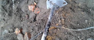
Measuring current distribution in single-core cables
On the power cable, currents flowing both in the conductors and in the metal sheaths and armor are measured. Measurements are made using current clamps.
Depending on the sheath material, armor and position of the cable in space, the currents in them can reach 100% relative to the core current and greatly affect the heating of the cables. Simultaneously with measuring currents at loads close to the rated load, the temperature of the outer covers of the cables must be measured, from which the temperature of the core can be calculated. This temperature should be measured at the hottest point of the cable line and should not exceed the permissible temperature for a given measurement location. If the current distribution is uneven by more than 10%, when individual cables limit the throughput of the entire group of cables, measures must be taken to equalize the currents across phases.
Why does strength decrease?
There are several main factors that directly affect the decrease in network strength:
- Variable voltages;
- Temperature values.
In the first case, the network voltage may change. For example, at an electrical station the line reaches two hundred and twenty kilovolts, but in the event of a breakdown, the voltage can drop to one hundred and ten kilovolts.
After maintenance and repair, the voltage will return to its original value.
This voltage is called variable, changing over a certain time period. Due to the fact that many networks have existed in Russia for quite a long time, they have already acquired their own resources.
Alternating voltage is not a rare phenomenon for our networks.
When current passes, the cables heat up accordingly. Constant high temperatures can affect the conductor, which also affects the insulation layer. Breakdowns directly depend on different temperatures.