Content:
Operating principle
In a healthy three-phase network, the load is distributed evenly. In the event of a breakdown of any phase in a circuit with an isolated neutral, a ground fault occurs. Typically, in this case, a breakdown occurs on the electrical consumer's housing.
These can be either electric motors or metal equipment. If there is no grounding, then voltage appears on the devices. This situation is very dangerous when a person touches the body of the structure.
When there is an insulated neutral in the network, the current will drop to a minimum and become safe for the worker. Currently, this protection system is used:
- In two-wire DC networks.
- In electrical equipment operating in a three-phase network with voltage up to 1 kV.
- In low voltage circuits with protective devices.
Protective devices mean the use of isolating transformers or the use of additional insulation. The fact is that it is impossible to turn off too low a current using conventional fuses and circuit breakers.
Such equipment is simply not designed for such values. additional relay equipment is required , which will warn of an emergency.
Since these devices are difficult to operate, their maintenance is carried out only by highly qualified workers.
What is neutral
Let's say we have a transformer that has a tap from the very middle of the secondary winding. Let's apply an alternating voltage to the primary winding and consider how the voltage will change between the tapping point and the end points of the secondary winding. At moment 1, at the top point there will be a “plus” in relation to the tap, and at the bottom point there will be a “minus”. At moment 2, the voltage between the tap and the end points will be zero. At moment 3, the “plus” and “minus” will change places. If you make more taps from the winding, then the further such a tap is from the first tap and, accordingly, closer to the end of the winding, the more the voltage between it and the first tap will change. At the point of the first withdrawal there is neither excess nor deficiency of electrons. This point is called the “neutral point” (of the secondary winding of the transformer), or neutral. The expression “tension at a (certain) point” is often found in the literature. If you use it, you can say that the voltage at the neutral point is always zero.
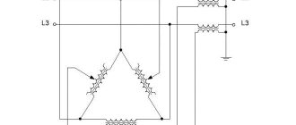
The secondary winding of a three-phase transformer is more complex. It consists of three identical windings, which can be connected “in a triangle” (we will not consider this case here) or “in a star”, where the beginnings of the windings are connected together. The point where they are connected is also called the "neutral point".
Effectively grounded neutral | Electrical Engineering Journal
An effectively grounded neutral (of a three-phase electrical installation) is a neutral of a three-phase electrical network above 1000V (1 kV and above), the earth fault coefficient in which is no more than Kzam = 1.4.
The term “solidly grounded neutral” is not currently used in networks above 1000V. Electrical installations in which the neutral is connected directly to the grounding device also refer to electrical installations with an effectively grounded neutral.
The earth fault coefficient in a three-phase electrical network is the ratio of the potential difference between the undamaged phase and the earth at the point of earth fault of the other or two other phases to the potential difference between the phase and the earth at this point before the fault.
In other words, when a phase is short-circuited in a network with an isolated neutral, the voltage between the ground and undamaged phases increases to linear - approximately 1.73 times; in a network with an effectively grounded neutral, the voltage on undamaged phases relative to ground will increase by no more than 1.4 times
This is especially important for high voltage networks, which reduces the amount of insulation in the manufacture of networks and devices, reducing the cost of their production. According to IEC recommendations, networks with an effectively grounded neutral include high and ultra-high voltage networks, the neutrals of which are connected to the ground directly or through a small active resistance
In the USSR and Russia, networks with an effectively grounded neutral are networks with voltages of 110 kV and higher.
Flaws
- The occurrence of large short circuit currents (SCC) through the grounded neutrals of transformers when one phase is shorted to ground, which must be quickly eliminated by disconnecting from relay protection devices. Most short circuits to earth in networks of 110 kV and above are self-correcting and the power supply is usually restored by automatic reclosing.
- Increased cost of constructing a grounding loop capable of discharging large short-circuit currents.
- A significant single-phase short-circuit current, with a large number of grounded neutrals of transformers, can exceed the value of a three-phase short-circuit current. To eliminate this, a mode of partially ungrounded transformer neutrals is introduced (some 110-220 kV transformers operate with an isolated neutral: the neutral terminals of the transformers are connected through disconnectors, which are in the off state). Another way to limit short-circuit current is to ground is the grounding of transformer neutrals through active current-limiting resistances.
Features of an effectively grounded neutral
According to PTEEP, the maximum permissible resistance value of a grounding device for networks with an effectively grounded neutral (for electrical installations above 1000 V and with a large ground fault current - over 500 A - for each object) is 0.5 Ohm, taking into account natural grounding (with the resistance of an artificial grounding device - no more than 1 Ohm). This is caused by the need to pass significant currents during a short circuit. to the ground, high and ultra-high voltage network, the requirement to limit the voltage between the ground and undamaged phases, as well as the possibility of high touch voltages, step voltages and dangerous “removal of potentials” beyond the territory of the substation during accidents. The need for uniform distribution of potentials inside the substation and the elimination of the appearance of step voltages at a considerable distance from the substation is excluded by the so-called. potential equalization device, which is an integral part of the grounding device for effectively grounded neutrals. Special requirements for grounding devices with effectively grounded neutrals create significant difficulties for their calculation and construction, making them material-intensive, especially for soils with high resistivity (rocky, rocky, sandy soils) and cramped construction conditions.
Notes
- PUE - rules for electrical installations, 6th and 7th edition.
- PTEEP - rules for technical operation of consumer electrical installations.
Total views: 135, Views per day: 1
www.el-info.ru
- Effectively grounded neutral and solidly grounded differences
- Testing of XLPE cable 10 kV
- Testing of XLPE cable 10 kV
- Pros and cons of CHP
- Pros and cons of CHP
- Bus disconnector 10 kV
- Bus disconnector 10 kV
- Disconnector rndz
- Disconnector rndz
- XLPE cable test report
- XLPE cable test report
What is a network with a grounded neutral and a network with an isolated neutral
A network with a grounded neutral is a network in which the neutral point is connected to the ground either directly or through low resistance. This connection is usually made in a substation. A special conductor is buried in the ground. The size, material of the conductor, burial depth - this is determined by special rules set out in regulatory documents. A separate wire goes from the grounding conductor to the network. It is called PEN - conductor. Translated, this means that this wire is simultaneously
- grounding
- zero worker
What this means will be explained below.
If the neutral point is not connected to ground or is connected through a large resistance, then such a network is called a network with an isolated neutral. In such a network (here we are considering networks with voltages up to 1000 Volts) there may also be a grounding wire. Since it is only grounding, it is called PE - conductor (without N). Explanation below.
If the voltage in the network is less than 1000 Volts (for example, 380/220 Volts) and there are no transformers in the network between the substation transformer and the consumer, then this is a network most likely with a grounded neutral. An exception is networks of enterprises with special operating conditions, for example, mines.
If between the substation transformer and the consumer of electricity there is also a transformer in which the neutral point of the secondary winding is not connected to the ground, then the section from the secondary winding to the consumer is essentially a network with an isolated neutral. Examples are step-down transformers, including in taps, in machine tools, etc.
Concept of isolated neutral
Most often, the consumer is faced with a grounding neutral. It is connected to the ground loop directly or through a device with low electrical resistance. An isolated neutral is a neutral that is not connected to ground or is connected through a device with a high dielectric resistance.
During network operation, current leaks constantly occur. They cause 2 types of short circuits: to ground and to body. The first option is a random connection of parts of devices that are energized with parts that are not isolated from the ground. The second is the contact of parts of the power plant that are energized with parts that are not energized in normal mode.
- If the fault current of the device to ground and the frame does not exceed 500 A , it is called an installation with low ground fault currents. Lines with voltages up to 1 kW and higher with an insulated neutral of a transformer or generator operate with such currents. Most often these are 3-phase systems with line voltages of 220, 380 and 660 V.
- If the frame or ground fault current is greater than 500 A , this is an installation with high fault currents. Such equipment operates with a solidly grounded neutral at voltages of 110 kV and higher.
The zero operating mode determines the insulation level, the magnitude of voltage and current, the conditions for turning on and off the protective relay, the choice of service equipment, etc.
According to the safety level, all installations are divided into networks up to 1000 V inclusive and over 1000 V.
Grounding in networks with isolated neutral
First, let's look at networks with an isolated neutral. In a network with good insulation, leakage currents and capacitive currents occur (Fig. 1). They flow both between phases directly (this is not shown in Fig. 1) and through the ground. The magnitude of these currents, however, is small. All electricians must remember the permissible insulation resistance value - at least 0.5 Mohm. The current at a voltage of 220 volts and a resistance of 0.5 MΩ will be 0.00044 A. Half a thousandth of an ampere.
However, leakage currents (and capacitive ones) can cause damage, and even death, if a person touches a phase wire (Fig. 2). The higher the network voltage, the more dangerous such currents are.
What happens if the insulation is broken in one place in the circuit and a short circuit occurs? A short circuit either to ground or to a metal structure (support, motor housing, lamp housing, distribution cabinet housing, etc.) connected to ground. Let us assume that in other places the insulation is intact (Fig. 3). There will be currents through leakage resistances and capacitances.
If, during such a short circuit, a person standing on the ground touches another phase, it will be mortally dangerous for him - he will be under linear voltage, that is, under voltage between two phases (Fig. 4).
What happens if another phase shorts to ground in another place? Current will flow between the phases (Fig. 5). Protection may work. Or it might not work. It may not work right away. This will depend on the magnitude of the current. And the magnitude of the current depends on the resistance of the earth, which can be very different, differ by orders of magnitude depending on humidity, freezing, soil composition (sand, clay or rock), etc. For a person exposed to such a current, this is deadly . And even if it does not touch the shorted conductors, it can be subject to step voltage.
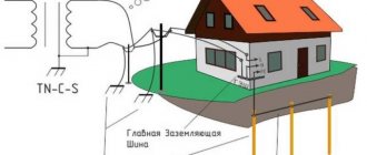
To avoid such a danger, protective grounding is done. Metal structures that can come under voltage are electrically connected to a conductor that is connected to the Earth. Just as in networks with a grounded neutral, it is usually connected to the Earth in a substation. According to special rules, a special piece of iron is buried in the ground and connected to a grounding wire.
What happens in a situation like in Figure 5, but if there is a protective ground? Look at Fig. 6 The fault current will flow through the grounding conductor. Current will also flow through the ground, but its magnitude will be much less than in Fig. 5. The total current will be large and therefore the protection will operate. For the protection to work, the resistance of the grounding conductor must be low enough. It should be thick enough so as not to burn out from high current.
Why do you need to connect the protective wire to ground? What does this give? Maybe it’s enough to simply connect the metal structures to each other with a conductor for the protection to work? The ground is an additional protective conductor (if the metal structures are connected to the ground), and in the event of a break in the main (protective conductor), it is the only one, although not very reliable (Fig. 5) This is how I understand it.
Applications of insulated neutral for networks over 1000 V
For safety of use and reduction of consumables in electrical networks over 1000 V, solid grounding insulating systems are most often used.
However, it is worth noting that in some transformers the cores are connected in a “three corners” rather than a “star” pattern and the central neutral is not provided initially.
For high-voltage wire systems, insulated solid grounding is extremely necessary for stable operation of the electrical network, since thanks to it the current voltage during a phase short circuit is minimal, and even when one phase is disconnected, the other two will continue to operate.
In addition, even a single contact with an uninsulated high-voltage wire is mortally dangerous to human life, therefore the system for ensuring safety must not be neglected.
In addition to the above-described factors for the need to use insulation, there is another one associated with damage to one of the phases.
As is known, when a grounded phase is short-circuited through another in a transformer of high-voltage wires, a significant overload occurs, which leads to the destruction of insulation and an interphase short circuit.
To eliminate the slightest possibility of a grounded arc and the ensuing emergency consequences, the isolated central neutral must be connected to the “ground” through a special reactor that extinguishes the arc.
It must be selected and installed according to all the characteristics of a particular network so that it provides maximum protection and security.
The reactor described above for arc extinguishing contributes to the following processes:
- Reduces short circuit current.
- Destroys the arc by affecting its unstable physical characteristics.
- Reduces the risk of a repeat arc fault by slowing down the current rise after extinguishing.
- Reduces reverse current voltage.
Grounding in networks with grounded neutral
Now let's move on to networks with a grounded neutral. What will happen if a person standing on the ground touches a phase wire in such a network (Fig. 7)? This is deadly. Although the voltage it will come under will be phase-to-phase (that is, if the voltage between phases is 380 V, the person will come under 220 V), the current flowing through it can be very large. The strength of the current and, accordingly, the degree of damage will depend on the resistance of the circuit.
The situation is also dangerous when a phase wire shorts to the ground or to a metal structure connected to the ground (Fig. 8). Compare Figure 8 with Figure 5. What do the situations depicted have in common? A large current passes through a person, depending on the resistance of the earth. Step tension is generated. The defense may or may not work. In Fig. 5 people find themselves under line voltage, and in Fig. 8 under phase voltage, but you can also die from phase voltage.
Now let's see what happens during a short circuit if protective grounding is performed (Fig. 9). Again, compare Figures 9 and 6. There are two purposes of protective grounding: 1. In the event of a short circuit, trigger the protection (protective shutdown) 2. Reduce the voltage and current that a person may be exposed to in the event of an insulation failure and short circuit.
The term (protective) nullification occurs. What do you mean by this? Grounding refers to the electrical connection to the neutral of the transformer. See Figure 9. It shows grounding, and since the neutral of the transformer is grounded, it is also a protective ground. In networks with an isolated neutral, grounding is not used. Why? It would greatly worsen the security situation. Why, I won’t write in detail; this is written about in Nayfeld’s manual. If in such a network, along with grounding, grounding were used, then we would have a network with a grounded neutral. as in Figure 9. It would lack the benefits of an isolated neutral network.
Repeated or additional grounding is often performed (Fig. 10). To quote Nayfeld: “Additional grounding does not worsen, but often improves the safety of networks and electrical installations.” When closed, it reduces the current on the neutral conductor, reduces the step voltage, and promotes faster response of the protection. For re-grounding, natural grounding agents are often used - pipelines laid in the ground, metal structures connected to the ground, and outer sheaths of cables.
Let me quote from the PUE: “1.7.61. When using the TN system, it is recommended to re-ground the PE and PEN conductors at the entrance to the electrical installations of buildings, as well as in other accessible places. For re-grounding, natural grounding should be used first. The resistance of the re-grounding electrode is not standardized.”
The meaning of the terms TN, PE, PEN is described below. What can and cannot be used as a natural grounding conductor, this is stated in PUE 1.7.109 and 1.7.110.
It is important to remember that it is unacceptable to perform additional grounding and at the same time disconnect from the main grounding wire. Why? Look at Fig. 11. In this case, during a short circuit, the protective shutdown may not work, since, as I have already explained, the ground resistance can be very different.
However, the PUE is allowed to use a grounding system that is not electrically connected to the grounded neutral of the transformer (Fig. 11-1). This system is called TT. It is only permitted in cases where electrical safety conditions in a TN system (that is, when grounded in the manner shown in Figure 9) cannot be ensured. An example of such a case is the network feeding a construction site. As a rule, the network is temporary, its reliability often leaves much to be desired. Therefore, it is allowed not to pull a PEN conductor to the construction site, but to make grounding next to it - bury (hammer) a piece of hardware into the ground (how and which one is determined by the rules) and connect the housings of electrical construction machines and mechanisms to it. In the TT system, the use of an RCD is mandatory.
I will quote PUE 1.7.57. “Electrical installations with voltages up to 1 kV of residential, public and industrial buildings and outdoor installations should, as a rule, receive power from a source with a solidly grounded neutral using a TN system.”
Therefore, the vast majority of 380/220 V networks in our cities, villages and enterprises are networks with a grounded neutral.
Isolated Neutral Definition and Terminology
The term “isolated central neutral” is described in the PUE, chapter 1.7, paragraph 1,7,6, as well as in GOST 2009-009, 12.1. These legislative sources clearly state that an isolated neutral is the central neutral of a generator or transformer of an electrical network, which is not connected to a grounding device or is connected, but through safety or alarm devices.
Also, the central isolated neutral can be a certain point, which is the center of the connection of the cores according to the “star” scheme.
Some, even professional, electrical specialists are convinced that an isolated neutral is an IT grounding system, which is described in PUE 1,7,3.
However, this is false information and deeply misleading, since the same paragraph of the PUE states that this system is used exclusively for power networks up to one kV.
In addition, paragraph 1,7,2 states that, depending on safety, isolated installations are divided into four categories from isolated to solidly grounded, as well as up to one kV and above.
Based on the above-described points of the isolated PUE, the conclusion follows: the isolated central neutral and the solid grounding system are completely different devices with different types of applications.
But how to determine which network, with an isolated or grounded neutral?
A network with an isolated neutral does not have a neutral working wire, but does have a grounding wire. If the network is working properly, the grounding conductor is not electrically directly connected to the phase conductors (although it may be connected through devices with high resistance). In networks with a grounded neutral, as a rule, although not always, 4 wires (cable cores) come from the substation to distribution points (panelboards, cabinets) - 3 phase and one grounding wire, also known as the neutral wire (this wire is called a PEN conductor) . The PEN conductor usually comes on a bus, which is connected to the panel or cabinet body and to which both neutral working and grounding wires are connected. Next, the neutral working wire is a separate conductor (it is also called an N-conductor), and the grounding wire is a separate conductor (PE conductor). Often the PEN conductor goes further and branches into a neutral working and grounding conductor at a lower level distribution point, for example, a floor panel.
The ground wire is also called the neutral protective wire, in contrast to the zero working wire. Both the neutral working and grounding wires have an electrical connection with the phase wires both through the transformer winding and through the load, for example, lamps. The resistance between them is low. In general, if the network has consumers operating from “phase” and “zero” (which can be checked, for example, by a voltage indicator on a working outlet), then this is a network with a grounded neutral. If the network has both a neutral working wire and a grounding wire, then this is a network with a grounded neutral.
Networks over 1 kV
Networks with voltages above 1 kV with an insulated neutral include networks from 3 to 33 kV. However, unlike lines with voltages up to 1 kV, the capacitive conductivity of the phases cannot be neglected here. When a ground fault occurs, the capacitive current of the undamaged phase also increases by 3 times compared to normal current. The absolute value is not that great. For example, with an overhead line length of 10 km and a voltage of 10 kV, the capacitive current is 0.3 A. Nevertheless, such networks are equipped with automatic insulation monitoring. The latter is triggered when the winding resistance in a phase decreases below the set value.
To prevent the occurrence of intermittent arcs, the isolated neutral of the transformer is connected through an arc suppression reactor.
The organization of networks with a voltage of 3–35 kV with an isolated neutral makes it possible to continue the operation of electrical receivers for 1–2 hours. However, the lines remain dangerous to humans.
How not to ground.
The ground wire should not go through the switch (Fig. 12). It may be accidentally switched off, rendering the grounding inoperative. It is also unacceptable to connect grounding through a fuse.
In Fig. Figure 13 shows what can happen if the ground is made as a branch of the neutral working wire. If the neutral wire is broken or burns out before such a branch
, an object grounded in this way will be energized.
But what if there is no separate grounding wire (in old networks)? Nayfeld's manual gives the correct grounding option, as in Figure 13-1. That is, grounding (it would be more correct to call it protective grounding) is taken from the common neutral working wire. However, if it burns out, the housing will again be under voltage. However, as I understand it (I’m not sure if I’m right), this solution complies with modern rules (Regulations for the construction of grounding networks 7.21, 10.10.10, read for yourself). Let's say you bought a chandelier with a clamp for the grounding wire, but in your old apartment the grounding wire does not stick out from the ceiling. 7.21 and 10.10.10 prohibit grounding (zeroing) the chandelier from the neutral working wire. According to the rules, you must extend the grounding wire (or neutral protective wire) from the branch box, panel, where (in the absence of a grounding wire) you can power it from the neutral working wire. Those who do not want to do this can justify themselves by the fact that “The standards apply to all newly constructed and reconstructed electrical installations” (PUE 1.1.1, Standards for the construction of grounding networks 1.1) and not ground the chandelier.
Typically, the neutral working and grounding wires are branched from the common wire (PEN conductor) in electrical panels (panels, cabinets). It is prohibited to electrically connect the neutral working and grounding wires after they have branched from the common wire (Fig. 13-2). (PUE 1.7.135.) Why?
Because then the operating current (as well as the short circuit current, if one happens) will flow not only through the zero operating current, but also through the grounding wire. If the housings of electrical equipment are connected to ground, some current, perhaps negligible, will flow through them to ground (Fig. 13-0-3). Equipment enclosures may be under voltage (perhaps negligibly, and possibly noticeably). Let’s assume that in such a situation, either the zero working wire or the grounding wire has failed (burnt out, broken) (wires often burn out at the connection points). Perhaps we won’t even know about it, because instead of the failed one, the remaining wire will work for us. Some might think this is good.
But what happens if the remaining wire subsequently fails? Let's look at another case first. Let's say the neutral and ground are not connected, and the neutral wire has burned out. (Fig. 13-0-1) By the way, since the workload passes through them, the neutral wires burn out much more often than the ground wires.
The network will experience a so-called “phase imbalance” - unevenness of the phase voltage, proportional to the unevenness of the load. (Load unevenness is when the total powers of consumers powered from different phases differ from each other). Single-phase equipment (such as light fixtures) can be exposed to either very high or very low voltage and fail. Three-phase equipment can also fail due to uneven voltage.
Now consider the case when zero and ground are connected by a jumper, and both of them are burned out. (Fig. 13-0-2) Find the differences from the previous picture. We have one more “pleasure”. The equipment housings will be energized (through the load). The magnitude of this voltage will depend on the unevenness of the load. The voltage will be highest if in such a situation there is a single-phase section of the network, for example, an apartment. This is if we do not have a short circuit (to the body or to the neutral wire).
What if a short circuit occurs due to which one of the wires (neutral or ground) burns out, and the other wire has already burned out earlier, or they both burn out? Then our cases will be under phase voltage (220 V), and single-phase equipment, powered from two of the three phases, will be under line voltage (380 V). See Figure 13-0.
Many visitors to this page complain about voltage on the ground wire. Let me clarify: the voltage between the grounding wire and the Earth’s potential, which may have, for example, water supply or heating pipes. This voltage can be shown by a capacitive voltage indicator - a screwdriver.
One of the possible reasons for this is the jumper between the zero working and ground wires, which I described above.
Another reason is the use of the ground wire as a neutral wire, possibly in combination with a break in the ground wire or poor contact of its connection. If all 220 volts are on the grounding wire , this is a dangerous matter, do not touch the housings
- a break (burnout) of the grounding wire in combination with a phase short circuit to it or to the housing is likely.
I will describe one more reason in more detail. As you know, any conductor has resistance. When current passes through it, a voltage drop occurs in it, proportional to the share of the conductor resistance in the total resistance of the circuit. This drop can be measured by connecting a voltmeter to the two ends of the conductor. If the conductor resistance is low (for example, it is a relatively thick and short cable), then the voltage drop is low. If it is large (for example, it is a long and thin wire of an overhead line), then the drop is large. This situation often happens in networks powered by overhead lines. Look at fig. 13-0-4 Let’s say that before the branching, the common neutral (grounding) wire (PEN - conductor) goes from the substation with an aluminum wire along poles across five streets. The resistance of this wire is relatively high. As a result, phase imbalance and voltage on the grounding wire and grounded housings are possible. By the way, the resistance of the phase wires of the overhead line will be just as high, because they go along the same poles, and, as a rule, have the same thickness. A
more uniform distribution of the load across the phases, as well as additional (repeated) grounding, can help here. PUE (1.7.102) prescribes it to be done at the ends of overhead lines and branches from them with a length of more than 200 meters.
What happens if you mix up the neutral working and grounding wires?
I wrote above that there may be voltage on the neutral working wire. This stress will end up on your body. The operating current will flow through the grounding wire, which will create a (possibly negligible) voltage on it and on the cases that are properly grounded. The likelihood of the ground wire burning out will also increase. If it burns out, the voltage will be on the housings that are properly grounded.
Here is another example of the consequences of improper grounding (Fig. 13-3). The left lamp is grounded (incorrectly) from the neutral working wire, the right one is grounded from the ground wire. Let's say our neutral main wire has burned out. Then our current will flow as follows: from the phase through the lamps to the neutral wire, then through the incorrect grounding of the first lamp to its body, then along the circuit on which the lamp hangs, along the beam, again along the circuit to the body of the second lamp and further into the grounding wire . The light will be on. But if you move the chains on which the lamps hang, they will spark, and even shock you. I have encountered this situation often.
Grounding should not be done in series.
Meanings of some terms
The meanings of the terms are explained in detail in the PUE and the Standards for the Construction of Grounding Networks.
What do the terms “TT, TN, IT grounding system”, etc. mean? If the first letter in these abbreviations is “T” (from the word “terra” - earth), then this is a system with a grounded neutral, if “I”, then with an isolated neutral. If the second letter is "T" (eg "TT"), then exposed conductive parts (eg housings) are grounded but not connected to the neutral. If the second letter is “N”, then the exposed conductive parts are connected to a solidly grounded neutral. The third and subsequent letters, if any (for example, “TN-S”) mean whether the neutral working and neutral protective (that is, grounding) conductors are separated or combined in one wire. If the third letter is “S” (from the word “separate” - separate), then each of these conductors runs as a separate wire throughout the system. If “C” (“common” is common), then they are combined in one wire. If "CS" (for example, "TN-CS"), then the common (neutral and ground) wire is then branched.
What do the terms “N-conductor, PE-conductor, PEN-conductor” mean? N—zero worker; PE - zero protective (grounding); PEN - combined zero working and protective.
Flaws
This is considered an emergency mode and does not involve long-term operation of the equipment. This mode has the following disadvantages:
- Finding a faulty area is quite difficult;
- The insulation of electrical appliances must be designed to withstand breakdown from line voltage;
- With a prolonged short circuit, the likelihood of electric shock to service personnel increases;
- Due to the constant exposure to arc overvoltages and the constant accumulation of defects, the service life of the insulation is reduced;
- Due to the occurrence of arc overvoltages, insulation damage occurs in different places;
- A single-phase ground fault in networks with an isolated neutral makes the operation of relay protection difficult;
- Possible occurrence of a small current arc at the site of a single-phase ground fault.
A large number of disadvantages significantly reduces the use of such a scheme in networks up to 1,000 V. Such a system has become more widespread in high-voltage networks.
What is potential equalization and why is it needed?
If there is a potential difference (voltage) and a conducting medium (for example, the human body) between two points, then a current will flow between them. The current can cause injury to a person, sparking, which will lead to fire and other harmful consequences. To avoid this, potential equalization is performed: parts of equipment, buildings and structures are either connected with a special conductor, or their current-carrying structures themselves are reliably connected to each other. They are also connected to the grounding (neutral) wire. Potential equalization is considered a measure complementary to grounding. How and in what cases to carry it out is written about in the Standards for the Construction of Grounding Networks (10-11-40, 10-12-3 and other sections).
Read Nayfeld, PUE, as well as Standards for the construction of grounding networks. Everything is more precise and detailed there.
- In particular, in the 7th edition of the PUE it is written:
- 1.7.101 What should be the resistance of the grounding device
- 1.7.102 About re-grounding overhead lines>
- 1.7.109 What can be used as natural grounding conductors.
- 1.7.110 What cannot be used as natural grounding conductors.
- 1.7.113 and 1.7.117 Sections of grounding conductors in electrical installations with voltage up to 1 kV
- 1.7.119 and 1.7.120 Main grounding bus
- 1.7.121 - 130 Standards governing grounding conductors (PE conductors)
- 1.7.121 - 131-135 Standards governing PEN conductors
- 1.7.142. Connections of grounding conductors
- Among other things, the Standards for the Construction of Grounding Networks state:
- 1.3.1.1 Basic rule for electrical installations
- 1.3.1. Grounding of electrical equipment installed on overhead line supports
- 1.4. Using Natural Grounding Devices
- 1.5. Combining grounding devices
- 1.11. Application of RCD-D as additional protection in electrical installations up to 1 kV
- Chapter 2 How potential equalization is performed.
- 2.6.1 What is subject to grounding or zeroing
- 2.7.1 What does not need to be grounded or neutralized
- Chapter 5 electrical installations with voltage up to 1 kV network with a grounded neutral (TN system)
- 5.18 - 5.20 Grounding overhead lines
- 7.1 - 7.6 What can be used as grounding and combined conductors
- 7.7 The need to ground support cables, cable armor and metal hoses
- 8.1 Natural ground electrodes
- 8.10 Artificial ground electrodes
- 8.25. Connection of parts of the grounding conductor, connection of grounding conductors with grounding conductors
- 10.1.2. Grounding current transformers
- 10.2 Grounding cables
- 10.3 Grounding overhead lines
- 10.4 Grounding of electrical machines
- 10.5 Grounding of individual devices, panels, cabinets, boxes with electrical equipment
- 10.5.4. It is prohibited to connect more than two cable lugs to one neutralizing bolt (screw).
- 10.9 Grounding of portable electrical receivers
- 10.10 Electric lighting
- 10.10.4 In group lines supplying general lighting fixtures and plug sockets, the neutral working and neutral protective conductors are not allowed to be connected to a common contact terminal
- 10.11 Electrical installations of residential, public, administrative and domestic buildings
- 11/10/14. In buildings, cables and wires with copper conductors should be used.
- 10-11-24 to 10-11-39 RCD in buildings
- 10-11-40 potential equalization system in buildings
- 10-12 Rooms containing a bath or shower
- 10-13 Rooms containing sauna heaters
- 10-18 Lightning protection
Frequently asked questions:
Why is the neutral wire thinner than the phase wires?
The neutral wire is made thinner than the phase wires, because the current that flows through it is less than the current that flows through the phase wires.
If the load across the phases in the network is distributed (strictly) evenly, the currents in it flow from phase wires to other phase wires. The voltage drop in the network will be such that the neutral potential will be on the neutral bus and the current in the neutral wire will be zero. When the loads are uneven, a current appears in the neutral wire. The greater the unevenness, the larger it is.
Why is a neutral wire needed?
I wrote above that the neutral and grounding conductors usually come from the substation in one wire, and why a grounding wire is needed. Now about the function of the neutral working wire. It is needed to avoid the “phase imbalance” that I described above. Although electricians strive to achieve load uniformity (for example, by connecting an equal number of apartments to each phase), unevenness still occurs. You flipped the switch and you have already changed the load ratio. Why is there no “phase imbalance” when there is a neutral wire? Firstly, when many consumers are connected to the neutral wire, load unevenness appears to a much lesser extent. When you turn on the TV to watch football, there is a chance that your neighbors, who are “sitting” on other phases, also turn on their TVs. Secondly, the neutral wire is connected to the neutral. Neutral is a point in the secondary winding of a transformer to which three identical symmetrical windings are connected at one end. At the other end they are connected to the phase wires. Let's assume that the load is distributed evenly across the phases. And suddenly in some phase it increases.
The following will happen:
- The load resistance in this phase will decrease.
- The voltage drop across the load will decrease, and therefore
- The voltage between this phase and zero should decrease, but
- The current in the load will increase, and therefore
- The current in the corresponding third of the secondary winding will increase
- The magnetic field of the secondary winding will increase
- This magnetic field is directed in such a way that it reduces the inductive reactance of the corresponding sector of the primary winding, and therefore
- This inductive reactance will decrease further
- In the primary winding (in its corresponding third) the current will increase, and therefore
- Its magnetic field will strengthen
- This magnetic field will create a higher voltage in the corresponding sector of the secondary winding, and therefore
- The voltage between this phase wire (phase) and neutral (zero) will remain stable
This ensures uniformity of phase voltages.
Why ground the neutral
Connecting the common point of the output windings of power transformers to the physical ground is carried out for three purposes:
- To ensure the safety of people servicing electrical installations and themselves.
- To maintain the quality of supplied power within industry norms.
- Receiving a household voltage of 220 volts.
Ensuring people's safety
In our country, all electrical networks with a voltage of 0.4 kV are made four-wire and with a solidly grounded neutral, and duplication of the connection of the neutral conductor (it extends from the common point of connection of the three windings of the power substation transformer) with the physical ground is carried out on every third support. This is done to ensure that the grounding resistance is always no more than a few ohms.
If the neutral is reliably connected to the ground, accidental contact with one phase will not lead to electric shock to a person if he is wearing shoes with soles that have dielectric properties. For the reason that the total resistance of the arm-leg line is at least 1 kOhm, and this is tens of times greater than that of the conductor connecting to the ground electrode. The current simply will not flow through a person.
If the neutral conductor is grounded, then a single-phase short circuit to physical ground is accompanied by an avalanche-like increase in current strength, which is accompanied by the occurrence of an electric arc and the release of a large amount of heat, as a result of which the emergency conductor melts and its contact with the ground ceases.
To speed up the shutdown process, automatic electromagnetic switches are installed in the line, which de-energize it when overcurrents (short circuit) occur. This reduces the duration of electric current on people or electrical installations. Which gives a chance that the former will remain alive and relatively unharmed, and the latter will remain functional.
Maintaining the quality of supplied electricity
In the conductor common to the three windings of the transformer, the current strength is zero and there is no electric field voltage. This is the result of the addition of three current vectors, the angle (phase shift) between which is 1200. But this only happens if all three phases are symmetrical to each other in terms of electrical parameters. In reality, they may differ, which will lead to a current arising in the neutral, and the consumer will be supplied, for example, not 380, but 320 or 450 volts. Grounding the neutral in a three-phase network forces the phases to align, due to the fact that the stray current flows to the ground.
This is especially true if electricity is supplied to power single-phase consumers. It is carried out by laying a three-phase line with a common neutral (four wires) and connecting groups of consumers to different phases. Since the level of energy consumption in apartments differs significantly - in one, for example, only the TV is turned on, and in another there is also a washing machine, the phase imbalance can reach a critical level.
If the connection to the ground electrode is not reliable enough and has a high resistance, the neutral wire, which is usually made with a smaller cross-section than the phase wire, may burn out. This leads to the fact that for some the voltage at the inputs will be almost 380 volts, while for others it will be about 110. Both modes are dangerous for household appliances and can lead to electrical injury to people or animals.
Household voltage rating
Household voltage 220 volts is removed between the phase line and the neutral; it differs from linear (between phases) by 1.7 times. To ensure stability of its value, the neutral is grounded.
Why does the neutral wire burn out?
Because current flows through it. It usually burns out in places where connections were made poorly. If the resistance of the connection is high, heat begins to be generated on it. Heat causes the connection to oxidize, its resistance increases even more, and it heats up even more. If the process starts, sooner or later the wire will burn out. Remember this simple wisdom: the larger the contact area, the more reliable the connection. And if a twist 1 cm long burns out in a month, 2 cm in a year, then a twist 5 cm long and longer will last (maybe) forever. Make the twist longer, do you really feel sorry for the wires?
For reliability, you can also twist a piece of uninsulated wire onto the twist.
It’s even better to solder or weld the twist. Nowadays, special caps are used that are screwed onto connections - “PPE”.
By themselves, they only increase the reliability of the connection, but I don’t believe that it’s enough to screw on the PPE and reliability is ensured. Carefully clean the surfaces to be joined (with a file, knife), but not with sandpaper (its grains can worsen the quality of the connection). When making a loop of wire for a bolted (screw) connection, weld it several times with a file (file) so that the contact area is larger. Tighten the screw or bolt until it stops, current will flow through it. Take care that the connection does not weaken over time. Use a good, non-rusty, non-oxidized washer or Grover washer. Do not connect copper and aluminum wires directly, use (steel) clamps for this. Top
Report bugs by email
To home page