Electricity is a dangerous substance that can cause many problems if not handled correctly. For example, if an electrical device shorts out and you touch it, a charge of current will pass through your body, which can kill.
To minimize the risk of electric shock, as well as to protect electronic equipment from overloads, electrical networks are grounded, creating a circuit in which excess energy goes directly into the ground. This is precisely why grounding is necessary in a private home, country house or any other place where electricity is used. Below is a diagram of how to properly create a grounding loop.
Why is grounding needed?
When a short circuit occurs, the temperature of the conductor will rise sharply, causing melting of both the insulation and the conductive strands themselves. If you touch the wires at the moment of a short circuit, current will flow through the body, which can be fatal. This happens because the current always tends to follow the path of least resistance - that is, into the ground.
Grounding is a path that directs electricity directly to the ground, where it cannot harm anyone. The current always chooses the path with minimal resistance, and the ground loop has exactly this property. When a power leak occurs, the excess is immediately sent to the ground loop. Thus, even if a person receives an electric shock, it will not be severe, since most of the electrical energy will go through the grounding system.
It turns out that grounding is an important component of the electrical safety system. It must be said that grounding is a necessary part of any objects that use electricity. According to the requirements of regulatory documents, any building containing alternating current networks with voltages over 100 W must be equipped with a grounding system.
Grounding not only ensures safety, but also protects household appliances. The grounding loop takes on excess load during network fluctuations, reduces the impact of interference and neutralizes the negative effects of electromagnetic radiation.
Grounding
When checking residential and non-residential premises, representatives of the electrical network pay attention to the presence of a grounding loop and the correctness of its implementation. Therefore, if you live in an apartment building, then you will not do grounding in the apartment with your own hands. The developer thinks through this issue at the stage of designing the entire house as a whole.
In such apartments, each electrical panel is equipped with a grounding line, to which grounding wires are routed from all apartments. In apartments, sockets and switches with a three-wire cable (with a ready-made “ground”) are installed. And modern household appliances are equipped with cords with a grounding conductor.
Here in a country house you have 2 options for the development of events:
- Seek help from qualified specialists;
- Install grounding at your dacha yourself.
With the first option, everything is clear: you pay money, specialists design the grounding system and install it. But to implement the second option, you need to fully understand this issue.
Let's consider the functions of the ground electrode:
- Takes voltage from the housings of equipment whose power supply has been damaged;
- Balances the potential of grounded devices and communication facilities (pipes, gas outlets, etc.);
- Guarantees the correct operation of electrical safety systems;
- Neutralizes static voltage.
The difference between a lightning rod and grounding
Do not confuse grounding with a lightning rod. Despite the fact that they operate on a similar principle, their tasks are different. A lightning rod is needed to receive a discharge from lightning and transmit it through a ground loop isolated from the internal network directly into the ground.
Grounding, in turn, serves to drain current from the internal home network in case of overload. In principle, grounding and lightning rods can have a common external circuit, subject to compliance with safety regulations. By the way, you can buy ready-made lightning protection kits that comply with all the rules and conditions for efficiency and safety.
Instructions for installing grounding
Having completed the preparatory work, they begin installation.
Excavation of trenches
Dig trenches to a depth of 0.5–1 m along the perimeter of the created contour. In the direction of the input shield, from the rod closest to it, they also dig a pit for the grounding bus. The width of the trenches is about 50 cm, so that a person can fit in it to work.
Circuit installation
Pointed rods are driven into the ground. They should protrude 20 cm above the bottom of the trench. Jumpers are placed between the electrodes and adjusted to length. A busbar is laid from the same material in the direction of the input panel. Its end is bent into the letter “G” and secured to the base of the house. Bending is needed to compensate for the expansion of steel during temperature fluctuations.
Ground loop device
Grounding is a special conductive structure made from materials with low resistance. The grounding system consists of two circuits connected to each other using a distribution board. The first loop is located in the building and is designed to transmit current to an external ground loop, most of which is underground. A grounding loop is made from large cross-section metal rods, which ensures instantaneous current transmission.
Grounding in a private house is:
- An internal circuit consisting of an extensive network of wires that connect to sockets, high-power devices and conductive channels (pipes). The individual conductors are combined into one core, which is connected to the external ground loop.
- External grounding. Several electrodes are deepened into the ground, connecting them with metal plates. The plates, in turn, are connected to the distribution board using a massive busbar.
The operating principle of grounding is quite simple - when excess voltage accumulates in conductors or devices, the circuit acts as a kind of fuse, quickly discharging current through a common circuit into the ground. Thanks to the almost unlimited capacity that the earth has, such a circuit allows you to utilize enormous voltage.
Grounding schemes for a private house
There are several grounding schemes in an individual cottage: TN-C, TN-CS and TN-S. The first letter in the abbreviation indicates the method of connecting the “ground” to the power source, the second deciphers the characteristics of the consumer.
TN-C circuit
This convenient variety is distinguished by the fact that the conductor simultaneously performs the functions of protection and a working device. This option is often used in old houses due to its ease of implementation and cost-effectiveness. However, due to the lack of a separate protection circuit during an accident, there is a possibility of a short circuit. In modern cottages this option is not used because it does not meet regulatory requirements.
TN-S circuit
In this circuit, separated conductors are used. In an emergency, no voltage is released to the body of the household appliance. This option is considered the safest because it protects against electric shock. However, to implement such a scheme you need to put in a lot of effort and spend additional money.
TN-CS circuit
This is a combined version in which two conductors coming from the power source are combined into one. In this case, an additional PE type protective conductor is installed at the entrance to the house. This scheme is recommended to be used as the main model in buildings for any purpose, including private houses. Its advantages are reliability and ease of assembly. Thanks to the use of an additional conductor, the likelihood of a fire during a short circuit is minimal.
Types of ground loops
To ensure the fastest and most stable flow of current into the ground, several electrodes are dug into the ground and connected using a thick busbar. The effectiveness of grounding largely depends on the location of the electrodes. By correctly positioning the conductive frame, you can speed up the absorption of current by the ground, thus improving the efficiency of grounding a private house.
There are 2 types of ground loops, each of which has its own advantages:
- Triangular outline. This type of grounding consists of 3 electrodes, which are first buried in the ground and then connected to each other in such a way as to form a triangle. The gap between the electrodes should be equal to the same depth to which the grounding pins are dug in, or slightly exceed it.
- Linear ground loop. To make linear type grounding, the electrodes are installed in one line or in a semicircle. The distance between the pins is 1 or 1.5 depth. The disadvantage of this type of circuit is that it is necessary to use more electrodes than when installing a triangular system, and therefore a linear circuit is installed when there is not enough space on the site to place a volumetric structure.
The described circuits are most often used when arranging grounding in a private house. It should be noted that the closed contour does not have to be triangular. It can be made in the form of a rectangle or, for example, an oval. The advantage is that even if the bus connecting the electrodes is damaged, the ground loop will continue to perform its function.
It is also important to know that linear grounding works on the principle of a garland and if the connecting bus is damaged, the cut section stops conducting current.
Basic grounding schemes
Experts recommend using standard and proven grounding schemes for summer cottages. This is justified by the fact that such schemes have been tested for several years and have already proven their reliability and safety.
The most reliable schemes are considered to be:
A recessed metal contour that is placed around the structure. Often the main material for drainage is classic construction reinforcement
The reinforcement rods are connected to each other by a welded metal busbar. Among summer residents, a scheme for placing three electrodes in the ground, which are connected to each other by a steel strip, is also common. The simplest scheme is to place a very long branch at a significant depth, which should be at least 6 meters. Important! Painting the grounding elements that perform the tapping function worsens the conductivity properties. Fundamental ground electrode
This scheme is very thorough, since it is a closed circuit, which is welded in the form of a metal mesh. Experts recommend laying such a mesh on the bottom row of reinforcement in the foundation. Installation of such grounding is possible only during the construction of the foundation.
Requirements for the grounding system
For grounding to function fully, all its elements must meet the relevant requirements, and installation must be carried out according to a strict scheme. If these conditions are not met, grounding in a private house will not effectively protect the house from voltage surges.
Conditions for installing the ground loop:
- The external part of the system should not be closer than 1 m from the house and no further than 10 m. A distance of 2-4 m is considered optimal.
- The electrodes are placed at a depth of approximately 2-3 m. Part of one of the pins is brought to the surface to connect an external bus.
- The cross-section of the external connecting strip, with the help of which the grounding is connected to the switchboard, cannot be less than 16 mm2.
- The connection of underground electrodes should be carried out exclusively by welding. In the distribution board, bolts can be used for fastening.
- Resistance cannot be higher than 4 ohms for 380 W and 8 ohms for 220 W.
When choosing a grounding kit, you need to navigate the location and take into account the specific location of the house. For example, if the structure is located in a cold region, the electrodes must be deepened below the soil freezing level, otherwise the structure will gradually be squeezed out to the surface.
If you want to arrange grounding in a private home according to all the rules, we recommend purchasing one of the ready-made grounding kits, each of which is made of durable materials with high resistance. Such kits are selected taking into account operating conditions, which is a guarantee of their effectiveness.
Designs of grounding devices
To install a grounding loop, you can assemble it yourself or buy a ready-made industrial kit, which will cost more money during installation, but will last several times longer and more reliably than a homemade assembly.
Before choosing an electrical grounding circuit, you should clarify the characteristics of the soil in which the circuit will operate and select the most suitable design for it. Reference data and recommendations for choosing a circuit can be provided by specialists from the nearest electrical laboratory.
The most favorable time for creating a ground loop is the period when a building is being designed for construction. In this case, it is possible to comprehensively plan lightning protection together with grounding conductors and a lightning rod, entrust labor-intensive operations to builders, and integrate technical solutions into the design of the building.
More often, for some reason, people think about this after the walls and roof are built, which is typical for all electrics. With this approach, we can recommend the following typical grounding schemes with:
- horizontal arrangement of electrodes;
- installation of four vertical electrodes.
Horizontal grounding conductors
The name of the structures is given by the method of placing electrodes at a relatively shallow depth in the horizontal soil layer. The most common designs are with one, three or sixteen electrodes.
The easiest way to ground
It is created in a short time, but does not last long. For the electrode, you will need to use a metal rod, angle, pipe or thick reinforcement rod; it is even permissible to use a steel sheet.
Simple grounding technology:
- the electrode is driven to a depth of two meters;
- a copper wire with a cross-section of 6 mm sq. is firmly attached to the stripped end of the protruding metal with a bolted connection;
- the free end of the conductor is brought out and mounted on the metal bus of the building circuit, to which all housings of electrical household appliances are connected with a PE conductor.
Video user Alex ZW recalls a forgotten method of driving a metal rod into the ground. I recommend watching it.
The single electrode method is not reliable, it works for a limited time, and requires periodic checks with resistance measurements. Therefore, it is used only for temporary residential facilities and industrial cabins, which serve for several months in one place and then are transported to another.
Three electrode design
The main material used is angles or pipes with pointed lower ends, which facilitate their penetration into the ground when striking with a sledgehammer or electric hammer.
The surface of the future circuit is marked on the ground in the shape of an equilateral triangle or segment with a distance between electrodes of 2.5 meters. Then a trench is dug to a depth of half a meter and electrodes are driven into the ground at its corners to the full depth so that only space remains for connecting them to the steel strip by welding.
The free end of the metal strip is brought to the surface of the earth and connected to the house bus. The trench is completely backfilled.
After installation is completed, it is necessary to measure the circuit resistance and if the standard characteristics are violated, an additional electrode will have to be added.
In practice, there is a case when home-grown electricians propose to improve the conductivity of the circuit by spilling the surface of the earth where it is located with salt solutions. This temporary measure, of course, will reduce the electrical resistance of the soil and the measurement will show the norm.
But you can’t resort to this method for two reasons:
- the introduced salt solution will constantly affect the metal of the electrodes;
- after the spilled water quickly dries, the soil resistance will increase sharply, and the owner of the house will be misinformed.
The method of creating a circuit of three electrodes is most common in central Russia and is suitable for use according to most soil characteristics.
Sixteen electrode design
An increased number of grounding conductors creates a larger area of contact between the metal of the circuit and the ground and better spreading of currents to the ground potential. Due to this, better electrical conductivity of the circuit is created, capable of more reliably transmitting applied loads.
This design is used for soils with low groundwater levels in the ground. It requires increased consumption of material, the presence of a square-shaped platform with a side of 25 meters.
The manufacturing method, installation, and testing correspond to the grounding circuit with three electrodes.
Vertical ground electrode
It is made in a factory, but it is quite possible to assemble it yourself. This will require specialized tools and devices.
Thanks to automated production, grounding electrodes are made of four cylindrical electrodes from steel alloys coated with a layer of copper using electroplating technology. The stacked structure is assembled sequentially from two-meter rods, connected alternately using a durable threaded adapter.
The first rod is driven into the ground with an electric hammer and an adapter with the next rod is mounted on its upper part. After this, the prefabricated electrode is again buried to install the next part.
The total minimum length of vertical electrode penetration is 12 meters. It can be increased to fifty and further as needed.
All four electrodes are equipped with special clamps and connected by a busbar, which is mounted to the grounding bus of the house.
Vertical grounding conductors have better electrical performance than horizontal ones and last much longer. However, they also require periodic monitoring of the technical condition by measurements.
Which scheme to choose
Before proceeding directly with the grounding installation, it is necessary to select a scheme according to which the electrodes will be located underground. It is necessary to correctly select the materials from which all structural elements will be made, as well as calculate the dimensions of the electrodes and connecting parts. Grounding parameters are calculated using a special formula, which allows you to accurately select the layout of all protective elements.
When it comes to grounding patterns, a triangle is considered the most effective. It is the three-way circuit that ensures rapid and complete absorption of electricity by the ground, evenly distributing the current over the surface.
If the size of the area does not allow placing a volumetric triangular structure, the electrodes are placed in one line, in a semicircle, or, for example, in a wave. However, most experts agree that the best arrangement of electrodes is considered triangular, since it ensures the fastest and most efficient absorption of current by the ground.
So which circuit should you choose?
Let's first figure out under what conditions certain types of circuits are used.
Closed triangular outline:
- The 220/380V network is brought into the house through a power input panel.
- Continuous total power consumption is more than 3 kW.
- Availability of industrial-type electrical appliances with a provided grounding connection (lathe, circular saw, drilling machine, etc.).
Two groups of linear grounding conductors:
- The total power consumption is over 1 kW for 20 minutes.
- The electrical wire is routed underground through an external panel.
- The house has at least one of the communications (communications, gas, water, sewerage).
There are many other factors, so in this case it is best to consult a specialist and do the work yourself.
Selecting materials for the ground loop
As a rule, grounding electrodes are made of steel, because... this material has sufficient strength. Using a steel profile, the electrodes can simply be driven into the ground, which greatly simplifies installation.
The cross-section of grounding conductors may be different. For example:
- A rod with a cross section of 16-18 mm is one of the most common options. In this case, it is not recommended to use reinforcement, since it is made of hardened steel, which has increased resistance. In addition, the corrugated surface does not fully ensure current dissipation.
- Corner. The best option is a corner of 50x50 mm with a wall thickness of 4-5 mm. To speed up installation, the corner is sharpened at the bottom.
- Pipe. The diameter is selected according to calculations (most often pipes with a diameter of 50 mm with a wall thickness of 4-5 mm are used). In arid areas, thick-walled pipes are used, drilling holes in the lower part, into which salt water is poured to improve the dispersive ability of the soil.
Steel is the most suitable material for grounding a private home, not only because of its high strength, but also due to its suitable resistance. Provided that the calculations are made correctly, steel electrodes are able to effectively utilize excess voltage, regardless of the scale of the leak.
How to do proper grounding at your dacha: the dangers of lack of grounding for your home
The construction of a private house or country house always involves a large amount of electrical work. In this range of tasks, along with supplying power to the house, installing distribution and protective equipment, laying internal lines, a well-planned and executed grounding system is no less important. Unfortunately, when carrying out self-construction, inexperienced owners quite often forget about this point or even deliberately ignore it, trying to achieve some kind of false savings in money and labor costs.
How to make grounding at the dacha
Meanwhile, the grounding system is of extreme importance - it can prevent many troubles that can lead to very sad or even tragic consequences. According to existing rules, electrical network specialists will not connect a house to a power line if this system is not in the house or if it does not meet the necessary requirements. And the owner, one way or another, will have to decide the question of how to make grounding at the dacha.
Expert opinion: Afanasyev E.V.
Chief editor of the Stroyday.ru project. Engineer.
In modern urban buildings, a grounding loop is necessarily provided at the design stage of the building and its internal communications. The owner of a private home will have to decide this issue himself - invite specialists or try to do everything himself. There is no need to be afraid - all this is a completely doable task.
Why is a ground loop needed?
In order to understand the importance of grounding, basic concepts from a school physics course are enough.
The vast majority of private homes are powered by a single-phase 220 volt AC network. The electrical circuit necessary for the operation of all devices or installations is provided by the presence of two conductors - actually, a phase and a neutral wire.
Typical wiring diagrams for a single-phase electrical network
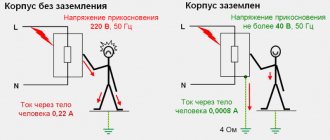
The design of all electrical appliances, tools, household and other appliances includes insulation elements and protective devices that should prevent voltage from entering conductive housings or casings. However, the possibility of such a phenomenon can never be excluded - the insulation can be broken by a discharge, burn out from unreliable, sparking contacts in wire connections, circuit elements can fail, etc. In this case, phase voltage may reach the body of the device, touching which becomes extremely dangerous for humans.
Situations are especially dangerous if there are metal objects near such a faulty device that have so-called natural grounding - heating risers, water or gas pipes, open reinforcement elements of building structures, etc. At the slightest touch to them, the circuit can close, and a deadly current will pass through the human body towards a lower potential. Similar situations are no less dangerous if a person is standing barefoot or in wet shoes on a wet floor or ground - there are also all the prerequisites for shorting the alternating current circuit from the device body.
One of the expressed properties of electric current is that it will definitely choose a conductor with minimal resistance. This means that it is necessary to create in advance a line with minimal resistance and zero potential, along which, in the event of a breakdown on the housing, the voltage will be safely discharged.
The resistance of the human body is an unstable value, depending on individual characteristics and even on the temporary state of the person. In electrical engineering practice, this value is usually taken as 1000 Ohm (1 kOhm). Therefore, the resistance of the ground loop should be many times lower. There is a complex calculation system, but they usually operate with values of 30 Ohms for the household electrical network of a private house and 10 Ohms if the grounding is also used as lightning protection.
The RCD will work correctly only if there is a ground loop
It may be objected that all problems can be completely solved by installing special protective devices (RCDs). But for the correct operation of the RCD, grounding is also necessary. If even the slightest current leak occurs, the circuit will close almost instantly and the device will operate, turning off the dangerous section of the home electrical network.
Some owners are prejudiced that for grounding it is enough to use water supply or heating pipes. This is extremely dangerous and completely unreliable. Firstly, it is impossible to guarantee effective stress removal - the pipes may be heavily oxidized and may not have good enough contact with the ground, and in addition, they often have plastic areas. Electric shock cannot be ruled out when touching them in the event of a breakdown of the power supply to the housing, and neighbors may also be exposed to such a danger.
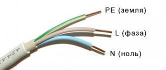
Plug and socket with grounding contact
Most modern electrical appliances are immediately equipped with a power cable with a three-pin plug. Appropriate sockets must also be installed when installing wiring in the house. (Some older model electrical appliances have a contact terminal on the body for a ground connection instead.)
Color marking of single-phase cable wires
There is a strictly defined color “pinout” of the wires: the blue wire is definitely “zero”, the phase can have different colors, from white to black, and the ground wire is always yellow-green.
And so, knowing this, some “wise” owners, wanting to save on updating the wiring and organizing full grounding, simply make jumpers in the sockets between the neutral contact and the grounding. However, this does not solve the problem, but rather aggravates it. Under certain conditions, for example, in the event of a burnout or poor contact of the working zero in some part of the circuit, or in the event of an accidental phase change, a phase potential will appear on the device body, and this can happen in the most unexpected place in the house. The danger of electric shock increases many times in such a situation.
Grounding is a reliable protection against many troubles
The conclusion from all that has been said is that grounding is a mandatory structural element of the home electrical network. It immediately performs the following functions:
- Effectively removes voltage leakage from conductive parts, touching which can cause electric shock.
- Equalizing the potential of all objects in the house, for example, grounded appliances and heating pipes, water supply, gas supply.
- Ensuring the correct operation of all installed safety systems and devices - fuses, circuit breakers or RCDs.
- Grounding is also important in preventing the accumulation of static charge on the housings of household appliances.
- It is of particular importance for modern electronics, especially computer technology. For example, the operation of switching power supplies for computers is very often accompanied by the induction of voltage onto the housing of the system units. Any discharge can lead to failure of electronic components, malfunctions, and loss of information.
Now that the importance of the grounding system has been explained, we can move on to the question of how to make it yourself in a private home.
Prices for protective automation
Protective automation
What are the types of grounding systems in private homes?
So, a well-executed grounding system should provide reliable contact with zero ground potential and with the minimum possible resistance of the created circuit. However, soil is different from soil - its different types seriously differ from each other in resistivity:
| Soil type | soil resistivity (Ohm × m) |
| Sand (for groundwater levels below 5 m) | 1000 |
| Sand (at groundwater level above 5 m) | 500 |
| Fertile soil (chernozem) | 200 |
| Wet sandy loam | 150 |
| Semi-solid or forest-like loam | 100 |
| Chalk layer or semi-hard clay | 60 |
| Graphite shales, clayey marl | 50 |
| Plastic loam | 30 |
| Plastic clay or peat | 20 |
| Underground aquifers | from 5 to 50 |
It is obvious that those layers that have the lowest resistivity are, as a rule, located at a considerable depth. But even when the electrode is deepened, the results obtained may not be enough. This problem can be solved in several ways - from increasing the installation depth of pin electrodes, to increasing their number, the distance between them, or the total area of contact with the ground. In practice, several basic schemes are most often used:
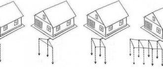
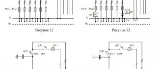
Possible grounding schemes in a private house
- Scheme “a” - installation of a recessed metal closed loop around the perimeter of the house. As an option - shallowly driven pins connected in a ring by a bus.
In dacha construction, it is used infrequently due to the large volume of excavation work or due to the peculiarities of the location of buildings on the site.
- Scheme “b” is perhaps the most popular among owners of suburban housing. Three or more moderately recessed pin electrodes connected by one busbar - this design is easy to make yourself, even in a limited space.
- Diagram “c” shows grounding with one electrode installed at a greater depth. Sometimes such a system is even installed in the basement of a building. The scheme is convenient, but not always feasible - it is almost impossible to implement it on rocky soils. In addition, for such a grounding system, you need to use special electrodes - we will talk about it below.
- Scheme “d” is quite convenient, but only if it was thought out at the stage of designing the house, and executed during the pouring of the foundation. It would be extremely unprofitable to implement it on a finished building.
So, the easiest way to implement schemes “b” or, if possible, “c” with minimal costs.
Grounding using homemade metal parts
To make a grounding system of this type, you will need metal profiles, a welding machine, excavation tools, and a sledgehammer. In some cases, with complex dense soils, a hand drill may be needed.
Schematically, this system looks like this:
The most commonly used grounding scheme for a private house
The location of the buried electrodes is chosen so that it is as convenient as possible to bring the grounding bus to the distribution panel. The optimal distance from the house is 3-6 meters. Acceptable limits are no closer than one meter and no further than ten.
The dimensions indicated in the diagram are by no means some kind of dogma. So, the side of the triangle can be up to three meters in length, and the depth of driving the pin can be slightly smaller - 2.0 ÷ 2.5 m. The number of electrodes can also change - if the soil is dense and it is not possible to drive the pins to a greater depth, you can increase their number.
A good idea is to contact your local utility company in advance for recommendations on how to install a ground loop. These specialists probably have well-thought-out schemes that have been tested in this region. In addition, they will be able to help calculate the dimensions based on the planned load of the home electrical network - this also matters.
Rolled metal that can be used for buried electrodes
What can serve as electrodes? For these purposes, a steel corner with a shelf of 50 × 50 mm and a thickness of at least 4 ÷ 5 mm is most often used. Pipes can be used, preferably galvanized ones with a wall thickness of at least 3.5 mm. You can take a steel strip with a cross-sectional area of about 48 mm² (12 × 4), but it is more difficult to drive it vertically into the ground. If you decide to use a steel rod, then it is also better to take a galvanized one with a diameter of at least 10 mm.
To tie the pins into one circuit, use a 40 × 4 mm strip or 12 - 14 mm wire rod. The same material is suitable for laying a grounding bus to the point of its entry into the house.
- So, initially markings are made at the selected location.
Pit and trench for ground loop
- Then it is advisable to dig a small pit of the intended shape to a depth of 1 meter. The minimum depth is 0.5 m. At the same time, a trench is dug to the same depth - a grounding bus will go along it from the contour to the base of the house.
You don’t have to dig a pit, but limit yourself to digging trenches
- The task can be somewhat simplified by digging not a solid pit, but only trenches along the perimeter of the contour being created. The main thing is that their width allows free driving of electrodes and welding work.
The edges of the corners need to be cut and sharpened so that they fit into the ground more easily.
- Electrodes of the required length are prepared. The edge with which they will be driven into the ground must be sharpened with a grinder, cutting it at an angle. The metal must be clean and unpainted.
The electrodes are sequentially driven into the ground to the required depth.
- At the designated locations, the electrodes are driven into the ground using a sledgehammer or electric hammer. They are buried so that in the pit (trench) they protrude above the surface level by about 200 mm.
Electrodes are connected by welding with a steel strip
- After all the electrodes are clogged, they are connected with a common busbar (horizontal grounding conductor) made of a 40 × 4 mm metal strip. Only welding is applicable here, although you can find recommendations to use a bolted connection. No, to ensure reliable and durable grounding, this harness must be welded - a threaded contact placed underground will quickly oxidize, and the circuit resistance will increase sharply.
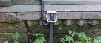
The busbar is welded to the circuit and routed to the base of the building
- Now you can lay a bus from the same strip to the foundation of the house. The tire is welded into one of the clogged electrodes and placed in a trench, then it goes onto the base of the building.
- The busbar is attached to the base. Not shown in the figure, but it is advisable to provide a small bend in front of the attachment point, the so-called “compensation hump,” to compensate for the linear expansion of the metal during temperature changes. A bolt with M10 thread is welded at the end of the strip. A copper terminal with a grounding wire will be attached to it, which will go to the distribution panel.
Terminal transition to ground wire
- To pass the wire through the wall or through the base, a hole is drilled and a plastic sleeve is inserted into it. The wire used is copper, with a cross-section of 16 or 25 mm² (it is better to check this parameter with specialists in advance). It is also better to use copper nuts and washers for connections.
In this case, the grounding bus from the fittings is brought inside the room
- Sometimes they do it differently - a long steel pin is welded to the tire, so that it passes right through the wall of the house, also through the sleeve. In this case, the terminal part will be indoors and will be less susceptible to oxidation under the influence of high air humidity.
Bronze distribution plate for connecting ground wires
- The grounding wire is connected to the electrical distribution panel. For further “distribution”, it is best to use a special plate made of electrical bronze - all the grounding wires going to the points of consumption will be attached to it.
Upon completion of installation, it is necessary to check the functionality of the system.
Do not rush to immediately fill the installed circuit with soil.
— It is recommended, firstly, to capture it in a photograph with reference to surrounding stationary ground objects - this may be required to make changes to the design documentation, as well as to carry out control and verification activities in the future.
— Secondly, it is necessary to check the resistance of the resulting circuit. For these purposes, it is better to invite specialists from the energy supply organization, especially since their call, one way or another, will be necessary to obtain permits.
If the test results show that the resistance is high, it will be necessary to add one more or even more vertical electrodes. Sometimes, before checking, they resort to tricks by generously watering the areas around the corners hammered into the ground with a saturated solution of ordinary table salt. This will certainly improve the performance, however, do not forget that salt activates metal corrosion.
Ordinary table salt significantly reduces the circuit resistance, but, alas, activates metal corrosion
By the way, if it is not possible to hammer in the corners, then they resort to drilling wells to the required depth. After installing the electrodes, they are filled with clay soil as densely as possible, which is also mixed with salt.
After the functionality of the grounding loop has been checked, it is necessary to treat the welds with an anti-corrosion compound. The same can be done with the bus going to the building. Then, after the mastic has dried, the pit and trenches are filled with soil. It must be homogeneous, not littered and free of crushed stone inclusions. Then the backfill area is carefully compacted.
Video: installation of a grounding loop using a metal corner
Using ready-made factory kits
Ready-made factory-made kits are very convenient for organizing grounding at the dacha. They are a set of pins with couplings that allow you to increase the depth of immersion into the ground as you drive.
Single pin grounding system
This grounding system provides for the installation of one pin electrode, but to a greater depth, from 6 and even up to 15 meters.
The kit usually includes:
- Steel pins 1500 mm long with a galvanized or copper-plated surface, or made of stainless steel. The diameter of the pins may differ in different sets - from 14 to 18 mm.
Set of rods for assembling the grounding electrode
- To connect them, they are equipped with threaded couplings, and for ease of penetration through the ground, a steel tip is included in the kit.
Threaded coupling and ferrule for easy driving
In some kits, the couplings are press-fit rather than threaded. In this case, one end of the ground rod is tapered by forging and has a ribbed surface. When impacted, a strong connection occurs and reliable electrical contact is achieved between the rods.
The pins can also have a press-fit coupling
- To transmit the impact, a special attachment (dowel) made of high-strength steel is provided, which will not be deformed by the impact of the hammer.
Dowel - a nozzle that will transmit the impact force from the hammer
- Some kits include a special adapter that allows you to use a powerful hammer drill as a driving tool.
Hammering the electrode using a hammer drill
To install such a grounding system, it is also advisable to dig a small pit up to a meter deep and the same in diameter, although some even prefer external placement.
Growing the electrode as it is driven into the ground
The pins are driven in sequentially and incrementally to the required depth.
Then a brass contact clip is put on the area left on the surface (about 200 mm).
Either a metal bus or a ground wire can be inserted into such a contact clamp
Either a conductive busbar made of a metal strip is inserted into it, or a grounding cable with a cross-section of 25 square meters is inserted. mm. For connection to the steel strip, a special gasket is provided, which does not allow for electrochemical contact between the ground of the rod and the steel (zinc). Subsequently, the bus or cable is brought into the house and connected to the distribution panel in exactly the same way as described above.
Video: manually driving pin electrodes
Prices for components for lightning protection and grounding
Components for lightning protection and grounding
What type of rod coating should I choose – galvanized or copper-plated?
- From an economical point of view, galvanizing with a thin layer (from 5 to 30 microns) is more profitable. These pins are not afraid of mechanical damage during installation; even deep scratches left do not affect the degree of protection of the iron. However, zinc is a fairly reactive metal, and while protecting the iron, it oxidizes itself. Over time, when the entire zinc layer has reacted, the iron remains unprotected and is quickly “eaten up” by corrosion. The service life of such elements usually does not exceed 15 years. And making the zinc coating thicker costs a lot of money.
Comparative test: galvanized (left) and copper-plated (right) electrode after 10 years of operation in an aggressive acidic soil environment
- Copper, on the contrary, without reacting, protects the iron it covers, which is more active from a chemical point of view. Such electrodes can serve for a very long time without compromising efficiency; for example, the manufacturer guarantees their safety in loamy soil for up to 100 years. But during installation, care should be taken - in places where the copper plating layer is damaged, a corrosion area will likely appear. To reduce the likelihood of this, the copper plating layer is made quite thick, up to 200 microns, so such pins are much more expensive than conventional galvanized ones.
What are the general advantages of such a set of grounding systems with one deeply placed electrode:
- Installation is not particularly difficult. No extensive excavation work is required, no welding machine is needed - everything is done with ordinary tools that are found in every home.
- The system is very compact; it can be placed on a tiny “patch” or even in the basement of the house.
- If copper-plated electrodes are used, then the service life of such grounding will be several tens of years.
- Thanks to good contact with the ground, minimal electrical resistance is achieved. In addition, the efficiency of the system is practically not affected by seasonal conditions. The level of soil freezing accounts for no more than 10% of the length of the electrode, and winter temperatures cannot in any way negatively affect the conductivity.
There are, of course, some disadvantages:
- This type of grounding cannot be implemented on rocky soils - most likely, it will not be possible to drive the electrodes to the required depth.
- Perhaps some will be put off by the price of the kit. However, this is a controversial issue, since high-quality rolled metal for a conventional grounding scheme is also not cheap. If we also add the duration of operation, simplicity and speed of installation, and the absence of the need for specialized tools, then it is quite possible that this approach to solving the grounding problem may seem even more promising from an economical point of view.
Video: how to ground your home using a modular pin system
How to connect the electrodes
In order for grounding to quickly remove current, the electrodes must be connected to each other using metal with low resistance. For this purpose, either steel or non-ferrous metals - aluminum or copper - are used. In this case, it is necessary to correctly calculate the cross-section of the connecting bus, which will ensure the efficiency of the entire system.
Minimum cross-section, depending on material:
- The copper busbar or wire must have a cross-section of at least 10 mm2.
- The aluminum connector cannot be thinner than 16 mm2.
- Steel strip with a cross-section of at least 48 mm2.
It is important to remember that non-ferrous metals, unlike steel, cannot be welded to ordinary iron, and therefore, if copper or aluminum is used as a busbar, threads are cut on the electrodes to secure the strip to the bolts.
Why is grounding important?
Firstly, this is the safety of the residents of the house, we have already mentioned this above.
Secondly, if you are building a new house, it doesn’t matter whether you do it yourself or all the work is done by a contractor, everyone must adhere to special standards: SNiP (building codes and regulations, GOST and PUE (rules for electrical installations).
According to these norms and rules, even during the construction of private houses, the so-called TN-S (house electrical system with grounding) is organized.
If this system is organized after the construction of the house, then you will have to dismantle, for example, all two-wire wiring and change it to three-wire, and this is very expensive.
Of course, you can then make grounding to only one outlet, for example, to connect a washing machine.
But it’s better to do this right away during construction and on all sockets. This is what experts recommend.
If you purchased an old private house, then, taking into account the operating features of modern electrical appliances, you will most likely also have to make a grounding system.
Indeed, in old houses, starting from Khrushchev’s times, the rate of electricity consumption per apartment did not exceed 1.3 kW, while there were safety plugs at 6A.
But in this case, you will be able to deal with grounding yourself, and we will talk about this further.
Do-it-yourself grounding
As can be understood from the above, installing grounding in a private house is a fairly simple operation that anyone can handle if they thoroughly prepare for it and calculate everything correctly.
First of all, you need to choose a place. This should be a flat area, sufficiently far from the house - it is advisable that people and pets do not walk along the grounded area. In addition, installation of the system closer than 1 m from buildings is not allowed. In this case, it is advisable to fence off the location of the ground loop, which will allow you to quickly find it in the future if any problems occur. The location of the electrodes must be marked.
Grounding installation occurs as follows:
- Marking is carried out (the most effective is the scheme in which the electrodes are arranged in the form of an isosceles triangle).
- A trench is dug along the entire marking (including for the bus that goes to the electrical panel).
- Electrodes are installed to a depth of about 2-5 meters, to which the connecting busbar is welded.
- The bus from the circuit is laid underground to the distribution panel, where it is secured with a bolted connection. If the wiring diagram suggests, the bus is connected to a splitter bus.
When everything is ready, the grounding system must be tested to ensure its effectiveness. To do this, the electrical resistance of the entire system is measured, which cannot be higher than the values specified in regulatory documents.
There is an easy way to check the grounding system. You need to take an ordinary 100 W lamp and connect it with one pole to the phase and the other to ground. If the lamp burns evenly and brightly, the circuit is assembled efficiently. If the glow is dim, you need to check the quality of the contacts. The absence of light indicates poor quality installation.
Grounding diagram in a private house
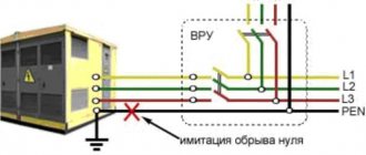
As a rule, power supply in private homes is carried out by overhead lines with a TN-C grounding system. In such a system, the neutral of the power source is grounded, and the phase wire L and a combined neutral protective and working wire PEN are connected to the house.
After the house has installed its own grounding loop, it is necessary to connect it to the electrical installations of the house.
- You can do this in two ways:
- convert the TN-C system to the TN-CS grounding system;
- connect the house to the ground loop using the TT system.
Connecting the house to the ground loop using the TN-CS system
As you know, the TN-C grounding system does not provide a separate protective conductor, so we are converting the TN-C system to TN-CS in the house. This is done by dividing the combined neutral working and protective PEN conductor in the electrical panel into two separate ones, working N and protective PE.
And so, two power wires approach your house, phase L and combined PEN. To get a three-wire electrical wiring in the house with separate phase, neutral and protective wires, it is necessary to correctly divide the TN-C system into TN-CS in the incoming electrical panel of the house.
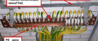
To do this, install a bus in the shield that is metallic connected to the shield; this will be a PE grounding bus; a PEN conductor will be connected to it from the power source side. Next, from the PE bus there is a jumper to the bus of the zero working conductor N; the bus of the zero working conductor must be isolated from the shield. Well, you connect the phase wire to a separate bus, which is also isolated from the switchboard.
After all this, it is necessary to connect the electrical panel to the grounding circuit of the house. This is done using a stranded copper wire, connect one end of the wire to the electrical panel, attach the other end to the grounding conductor using a bolt at the end, which was specially welded for this purpose.
Connecting the house to the ground loop using the TT system
For such a connection, it is not necessary to make any separations of the PEN conductor. Connect the phase wire to a bus isolated from the switchboard. You connect the combined PEN conductor of the power source to a bus that is isolated from the switchboard and in the future consider the PEN to be simply a neutral wire. Then connect the shield housing to the house ground loop.
As can be seen from the diagram, the grounding loop of the house does not have any electrical connection with the PEN conductor. Connecting the ground in this way has several advantages compared to connecting using the TN-CS system.
If the PEN conductor burns out on the power source side, all consumers will be connected to your ground. And this is fraught with many negative consequences. And so your grounding will not have a connection with the PEN conductor, this guarantees zero potential on the body of your electrical appliances.
It often happens that on the neutral conductor, due to an uneven load across the phases (phase imbalance), a voltage appears that can reach values from 5 to 40 V. And when there is a connection between the network neutral and the protective conductor, it can also occur on the housings of your equipment little potential arises. Of course, if such a situation arises, the RCD should trip, but why rely on the RCD. It would be better and more correct not to tempt fate and not lead to such a situation.
From the considered methods of connecting the grounding loop of a house, we can conclude that the TT system in a private house is safer compared to the TN-CS system. The disadvantage of using a CT grounding system is that it is expensive. That is, when using a TT system, protective devices such as RCDs and voltage relays must be installed.
I would also like to note that it is not necessary to make the outline in the form of a triangle. Everything depends on external conditions. You can place horizontal grounding conductors in any order, around a circle or along one line. The main thing is that their number is sufficient to ensure minimal grounding resistance.
Ready-made grounding kits
If you equip grounding yourself, you can significantly reduce costs. However, the selection and purchase of materials, their preparation and other manipulations associated with installation take a lot of time and, by the way, can also be expensive.
In cases where you do not have time to prepare, you can use a ready-made set of electrodes. This will allow you to significantly speed up the process, while saving on installation costs.
Examples of grounding kits:
- Grounding kit EZ – 6 from the manufacturer EZETEK. The kit includes 4 copper-plated electrodes with a diameter of 14 mm2, couplings, clamps, conductive paste, sealing tape, etc. The average price is 6,500 rubles.
- Galmar. The kit includes electrodes about 30 m long. The average price is 40,000 rubles.
- A product from a domestic manufacturer, which is adapted to difficult Russian conditions. Estimated cost – 8,000 rubles.
On the Russian market you can find a huge selection of ready-made grounding kits, differing in material of manufacture, connection method and installation technology. The installation depth of the electrodes can range from 5 to 40 m. The price varies between 6-40 thousand rubles.
Difference between grounding schemes for 220 V and 380 V
The grounding schemes for 220 V and 380 V have some differences that you need to remember when purchasing a kit. The differences relate to the internal circuit, while the external wiring is the same, regardless of voltage.
Thus, if we are talking about a voltage of 220 V, then 2 wires are supplied to the house, one of which bifurcates into neutral and ground, and the second is cut off into an insulator.
A line with a voltage of 380 V, as a rule, consists of 4 cores, one of which, as in the previous case, is bifurcated, and the other 3 are installed on insulators. The phase and neutral are passed through an RCD and a diphatomat.
Let's talk about the circuit
The circuit is a complex, but quite understandable structure.
It consists of external and internal devices, which in turn are divided into:
1. EXTERNAL DEVICES. Electrode stakes dug 2 meters deep, connected at the top by plates. A grounding conductor, which is round or flat steel, extends from the electrodes. The grounding conductor approaches the switchboard in the house and, as a rule, is connected to it through a copper wire.
2. INTERNAL DEVICES. Grounding wires that come from sockets, and directly the switchboard in which, using a special bus, the wires of the external and internal systems are combined.
Now let's look at how to install such grounding in your home yourself.
Installation errors
If the grounding installation of a private home is carried out by non-professionals, there is a risk of technical errors that reduce the efficiency of the system. We will list the most common mistakes, by preventing which you will ensure the energy security of your home:
- Electrodes cannot be painted, otherwise they will lose their ability to transmit current to the ground.
- The tire cannot be secured with bolts, because corrosion will quickly destroy the contacts.
- It is not recommended to place the grounding system far from the house - the distance significantly increases the resistance.
- If thin electrodes are used, corrosion will reduce the conductivity of the metal over time.
- Copper and aluminum conductors should not be connected to each other, as this will cause contact corrosion at the attachment point.
If disturbances occur in the structure, grounding loses its effectiveness. Given that an inefficient circuit ceases to conduct current, protection against short circuits is sharply reduced. Because of this, the grounding of a private home is in a vulnerable state, which can cause serious complications if a major short circuit occurs. That is why, if problems occur in the circuit, they must be corrected immediately.
Design features
Unlike the grounding loop, in the manufacture of which a metal profile (corner) is used as vertical and horizontal electrodes, in a modular-pin type system the structural elements are made of the following materials:
- vertical electrodes are made of copper-plated steel rods 1.5 meters long;
- horizontal electrodes - steel (copper) strip or copper wire;
- couplings - made of copper-plated steel, used to connect electrodes;
- connecting clamps - made of brass, used to connect vertical and horizontal electrodes, connection to grounded objects.
On the market for similar products, modular-pin grounding systems produced on an industrial scale are additionally equipped with the following components:
- tips made of steel;
- steel landing pad;
- special paste.
Tips are used to facilitate the installation of electrodes; a threaded connection is used for their fastening. The landing pad is fixed to the rod using a threaded connection and serves to transfer the forces of the vibrating hammer to the vertical electrode being driven.
A special paste is needed to treat the junctions of electrodes (couplings, tips) and the junctions of vertical and horizontal electrodes (couplings).
Treatment with paste allows you to protect the contact points from corrosion, thereby reducing the resistance to spreading in these areas of the grounding system.