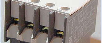
Checking, adjusting and setting up thermal relays type TRN, TRP
Very often one comes across electrothermal relays of the TRN and TRP types as maximum current protection in electrical facilities. I have already written in detail about these relays earlier. However, in these relays it is necessary to periodically configure and adjust the response settings. This is exactly what we will talk about today.
Before checking and adjusting thermal relays, you must:
– inspect thermal relays;
– create the necessary temperature conditions (not lower than +20 o C) in the room where they are installed. If it is impossible to create normal temperature conditions in the room where thermal relays are installed, testing of these relays must be carried out in laboratory conditions.
Carry out an external inspection of the thermal relays. During inspection, check:
1) reliability of tightening contacts and connecting thermal elements;
2) good condition of heating elements, condition of bimetallic plates;
3) clarity of operation of the mechanism associated with the relay contacts and the contacts themselves, absence of jamming or delays;
4) cleanliness of contacts and bimetallic plates, relay cooling conditions;
5) the absence of rheostats and heating devices near the relays, the possibility of blowing from fans.
When adjusting, it is necessary to take into account that the thermal elements at the manufacturer’s factory are calibrated at a temperature of 20 o ± 5 o C for thermal relays of the TRN series and at a temperature of 40 o C for thermal relays of the TRP series, therefore, when testing the relay, it is necessary to adjust the rated current supplied to the relay, taking into account ambient temperature.
TRN series relays are bipolar with temperature compensation, available for currents of 0.32 - 40 A with a set current regulator; for relays of type TRN-10a in the range from –20 to +25%, for relays TRN-10, TRN-25 – in the range from –25 to +30%.
The relays have only manual reset, carried out by pressing a button after 1 - 2 minutes. after the relay is activated. Thanks to temperature compensation, the set current is practically independent of air temperature and can vary within +3% for every 10 o C change in ambient temperature from +20 o C.
TRP series relays are single-phase, without temperature compensation, produced for a current of 1-600 A, with a set current regulator. The mechanism has a scale with five divisions on both sides of zero.
The division price is 5% for open execution and 5.5% for protected execution. At an ambient temperature of +30 o C, a correction is made within the relay scale: one scale division corresponds to a temperature change of 10 o C. At negative temperatures, the stability of the protection is disrupted.
Marking of electrothermal relays
The device designation takes the form of letters and numbers depending on the manufacturer. Most often, marking is done based on the abbreviated name, as well as:
- setting current parameters - written in numbers in brackets;
- letter designation of the structure;
- climatic version in the form of a range;
- current rating - numbers are used (1 - up to 25 A, 2 - up to 100 A, 3 - up to 510 A);
- features of the device - compatibility with direct and alternating current circuits, mono- and bistable devices, with acceleration or deceleration of on/off, with or without winding.
All designations are written in the relay passport.
Thermal relay: connection diagram, operating principle, purpose
Thermal relays are electrical devices whose main purpose is to protect the motor from excess load and, as a consequence, overload of the system as a whole. Today, the most common types of thermal relays are: TRN, RTI, RTT and RTL. The need to use thermal relays is due to the fact that the durability of any equipment directly depends on how often it is overloaded. Thus, when the rated voltage is regularly exceeded, the equipment heats up, which leads to aging of the insulation and, as a result, reduces the operating life of the installations.
Main types of relays
The compatibility of a relay device with a specific motor depends on its type. Manufacturers produce:
- TRP. A device with one pole and a combi heating system that protects asynchronous motors. Suitable for a network with a direct current of no more than 440 V, insensitive to shock.
- RTL. Prevents motor malfunction under conditions of phase loss, current asymmetry and overload, prolonged start-up, and jamming. Mounted on a DIN rail separately or together with the starter.
- PTT. The main purpose of the devices is to prevent long starts, overloads, and phase imbalance of asynchronous motors with squirrel-cage rotors.
- TRN. Two-phase switch for monitoring the start and functionality of the engine. Suitable for AC power, the contacts return to their original position manually.
- RTI. Thermal RTI relay has minimal power consumption and is compatible with circuit breakers or fuses. Installation is carried out on a special contactor.
- Solid state. Compact devices without active components. The principle of their functionality is to check the operating and starting current, and determine the average engine temperature. Installed in hazardous areas.
- RTK. A starting device that controls the temperature inside the equipment housing. It is used in circuits with relays as part of the automation equipment.
All devices only prevent emergency situations, and do not protect the network from short circuits.
Thermal relay connection diagram
Connection diagrams for electric motors that include a thermal relay can differ significantly from each other, depending on the technical need and the availability of various devices. However, in each of the circuits, the thermal relay must be connected in series with the starter coil. This provides reliable protection against equipment overloads. So, when a certain level of current consumed by the motor is exceeded, the thermal relay opens the circuit, thereby disconnecting the magnetic starter and the motor itself from the power source.
Simple repair of electric heaters. Basic faults
Regardless of the quality, sooner or later, almost all electric heaters begin to heat poorly, do not turn on, or no longer heat at all.
Repairing an electric heater yourself is not very difficult, since this class of devices is often not considered a complex device. In everyday life, people use a wide variety of electric electric heaters: electric infrared fireplaces, convectors, fan heaters and a variety of oil radiators. For all such devices, regardless of design features, the heating element is nichrome.
It should be noted that the simpler the design of the heater, the longer such a device will work, and it will be easier for the husband to figure out the breakdown and repair it. For quick and effective repairs, first of all, you need to understand how the heater works.
Regardless of the type of such devices, they all have basic common elements. The heaters are equipped with one or two key switches with which you can select one or two heating elements that will heat, as well as lamps indicating the operation of the heating element.
note
The heating element may have not two contacts, but three, with two separated heating coils inside. Immediately after the power cord and plug there may be a protective thermal fuse that will automatically turn off the heater after overheating, for example, if you cover the convector on top with a towel.
There may also be a tilt sensor that will work if, for example, the convector falls or overturns. In addition to the thermal fuse, there may also be a “circuit breaker” - an overload current fuse, for other emergency situations.
schematic design of heaters
Any diagnosis begins with disassembling the heater, but before disassembling it, you must turn it off and pull the plug from the socket. We unscrew the screws of the housing, most likely the control panel housing.
Having reached the connecting control panel with the thermostat, thermostat and other elements, we begin the test by testing the power cord. Next, we check the operation of all control keys and toggle switches by ringing them with a tester. Then all serial circuits.
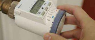
Thermostat
is checked by a tester and it should show zero resistance (short circuit) or close to zero on the contacts, this will indicate the serviceability of the thermostat.
In addition to the serviceability of the heater elements themselves, the cause of the breakdown may also be poor and unreliable contact of the conductors; over time, due to the difference in materials, they oxidize and rot, so attention should also be paid at this point. Then the protective elements are checked: position sensor and thermal fuse.
Thermal fuse
they call the tester; in a serviceable and cold state, there should be zero resistance (short circuit) on its contacts.
There can be several such thermal fuses in one housing and, as a rule, the larger the housing, the more thermal fuses it contains. It should be noted that the thermal fuse may be working (functional), but due to severe contamination of the filters and convection holes, they can immediately trip and turn off the heater.
What is a position sensor
, so this, in most designs, is some kind of weight that, when the heater is tilted or dropped, acts on a mini switch that already opens the voltage.
A working position sensor, in the normal vertical position of the heater, should have zero resistance (short circuit) on its contacts.
The main decisive point will be checking the heating elements
ov. In large heaters there are usually several of them, most often there are two. And often the reason for insufficient heating of the room is the failure of one of the heating elements. In most cases, the heating element cannot be repaired and is replaced with a similar one. How to check the heating element? The resistance at its contacts may vary, depending on the specific device, but it should definitely ring. Approximate resistance values can be in the range of 20 - 100 Ohms.
The heater does not turn on.
There may be several reasons. The socket, plug and electrical cord must be checked. Then disassemble and make sure there is mains voltage inside the device; it is best to use a 40W test light for this.
Important
The voltage is checked in the series circuit, thermal fuse, thermostat, thermal switch, heating element. The test under voltage should be carried out carefully or use the resistance testing method (with a multimeter) without voltage.
The fan heater turns on but does not heat.
The heater blows air but does not heat it, this situation clearly indicates a malfunction of the heating element, one of the sections of the spiral may be damaged, it is necessary to carefully inspect the entire length of the nichrome conductor, and also ring the heating element itself with a tester, the resistance should be somewhere around 70 Ohms .
In the event of a visible break or burnout of the nichrome conductor, you can try to restore it by slightly pulling the broken conductors to the center and carefully twisting them together with a reserve, then firmly inserting the “connection” back, but so that it does not move or close during operation randomly onto adjacent turns of the spiral.
Also, the reason for this operation may be a thermal fuse or bimetallic plates of the thermostat. In a cold state, they must be closed; sometimes it becomes necessary to strip them to improve the reliability of contact. Serviceable bimetallic plates should open from the heat of the soldering iron.
The fan heater heats up but the fan does not spin (does not blow).
If the blades are in good working order and are not wedged anywhere, then most likely the cause is the engines. But still, first you need to make sure that there is voltage supplied to the engine. Make sure that its shaft rotates easily and effortlessly. Next, you can check the engine with a multimeter; its contacts should ring and show at least some resistance.
If necessary, the motor can be disassembled and inspected inside; severe contamination may occur. Ring the windings, clean the commutator unit and inspect the tightness of the brushes. It may be necessary to apply machine oil to the bushings of the moving part of the engine. If the windings burn out, the motor must be replaced.
The heater turns off (due to overheating)
There may be several reasons. For example, a large heating area and a low-power convector, as a result of constant operation, the body and internal elements overheat, including overheating protection elements that turn off the device.
In other cases, the cause may be improper installation of the convector.
Advice
It is necessary to organize a free flow of incoming air to the lower part of the heater and a free outflow of hot air from the upper part of the convector; there is nothing to cover it with and not to create resistance to the release of heat from the convector.
The oil cooler is leaking.
Self-repair in such cases is a difficult and thankless task. Adhesives and sealants are useless in this case. To seal the holes, you need to drain the oil, fill it with water and use inverter welding for thin sheets. Boil the hole, first clearing the area of paint and corrosion. If oil is constantly leaking out, it should be understood that the oil will still need to be topped up, since for such a heater to work effectively, it is necessary to have 90% of the oil volume of the total capacity of the oil “tank”, the rest of the space should be occupied by air, it plays the role of a kind of cushion when the oil expands during heating
Operating principle of a thermal relay
Today, the most popular are thermal relays, whose action is based on the use of the properties of bimetallic plates. For the manufacture of bimetallic plates in such relays, as a rule, Invar and chromium-nickel steel are used. The plates themselves are firmly connected to each other by welding or rolling. Since one of the plates has a large expansion coefficient when heated, and the other has a smaller one, if they are exposed to high temperatures (for example, when current passes through metal), the plate bends in the direction where the material with a lower expansion coefficient is located.
Thus, at a certain level of heating, the bimetallic plate bends and affects the relay contact system, which leads to its activation and opening of the electrical circuit. It should also be noted that as a result of the low speed of the plate deflection process, it cannot effectively extinguish the arc that occurs when the electrical circuit opens. In order to solve this problem, it is necessary to accelerate the action of the plate on the contact. That is why most modern relays also have accelerating devices that allow you to effectively break the circuit in the shortest possible time.
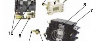
Repair or replacement of refrigerator start relay
Start-up protection relays are used to start the electric motor of the refrigerator compressor. They protect the motor from overload. Since the device has moving parts and contact groups, the relays can break. Any electrician can repair the start relay, including replacing it.
Reasons for failure of the refrigerator relay
A start-up relay is an electromechanical device and is intended to:
- to start a single-phase electric motor by briefly connecting the starting winding;
- to protect the electric motor from overheating by turning off its power, due to the high current of the operating winding.
As with all mechanisms that have moving parts, heating elements and contact groups, failures may occur during operation:
- the contact group may jam and not close the starting winding circuit. With this malfunction, the electric motor will not be able to start and after a couple of seconds the thermal protection of the relay will turn off the power. The malfunction is eliminated by restoring the mobility of the rod;
- the contacts may burn out and not turn on. The symptoms are the same as above. The malfunction can be eliminated by cleaning and aligning the contact patches;
- The thermal protection heating element may burn out. With this malfunction, the compressor simply will not turn on, because the chain is broken by a burnt-out spiral. In case of this malfunction, the relay must be replaced;
- loss of properties of the bimetallic plate to delay contact disconnection. With this malfunction, the contact will disconnect immediately when the coil heats up. The compressor will turn on and off briefly. A healthy bimetallic strip gives the electric motor time to start at increased starting current. If this malfunction occurs, the relay must be replaced.
To determine that the starting relay has failed, it is recommended to disconnect the relay terminals from the compressor and connect the compressor directly, giving a short impulse to the starting winding. If the compressor turns on, the reason must be looked for in the relay.
This can be easily done if there are symbols near the outputs:
- “S” – starting winding;
- “R” – working winding;
- “C” – general output.
Types of start-protection relays
Despite the variety of designs of start-up relays, two types of relays are used in refrigerators:
With induction start. The starting winding of a single-phase electric motor is switched on by a relay based on a solenoid.
With posistor switching. The starting winding of a single-phase electric motor is switched on through a posistor (a resistor with semiconductor properties).
Appearance of various models
Operating principle of start-protective relays with induction starting
Thermal protection operation. The thermal relay consists of a normally closed contact group, a bimetallic plate and a heater. A bimetallic plate is welded from two metals having different temperature expansion coefficients. The bimetallic plate can be directly heated (current travels through it) and indirectly heated through a spiral heater. When heated, the plate bends and opens the contacts. The compressor turns off. When the bimetallic plate cools down, the contacts close and power is supplied to the compressor again.
The starting relay is designed for short-term connection of the starting winding of the compressor motor when it is turned on. How does it work?
- When power is applied to the compressor motor, current flows to the operating winding of the motor through the relay solenoid coil. Since the engine consumes a large current when starting, a strong magnetic field appears in the solenoid winding, which draws in the core of the moving contact and the contacts close, connecting the starting winding;
- when the compressor starts, the starting current in the working winding of the electric motor drops to the nominal value and the magnetic field of the solenoid ceases to hold the core of the moving contact, the spring helps the core return to its original position, the contacts open and the starting winding of the electric motor is de-energized;
- The compressor is operating normally.
The start-up protection relay looks outwardly like a small box that is attached to the compressor housing, and in old refrigerators on the frame with screws, latches, spring brackets and rivets.
Operating principle of start-up protection relays with posistor connection
Start-up protection relays with posistors are used in almost all modern refrigerators. Their thermal protection works in the same way as for relays with induction starting (via a bimetallic contact).
What is a posistor, it is a type of thermal resistor with semiconductor properties. A cold posistor has little resistance, but when heated, the resistance increases sharply and stops passing current.
A posistor repeats the operation of moving contacts with a solenoid in start-protection relays with induction starting, only in the case of a posistor, there are no moving parts in the operation of this function and there is nothing to break.
At room temperature, the resistance of the resistor is insignificant, so the current flows to the starting winding as through an ordinary conductor. Since the posistor has little resistance, it gradually heats up and at a certain temperature the starting winding circuit opens. When the current supply is stopped, it cools down (switched off by the thermostat) and restores its properties to restart the compressor motor. A start-up protection relay with a posistor is installed directly on the compressor connector (three contacts).
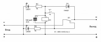
Electrical diagram
Your refrigerator owner's manual will tell you which brands of start relays can be used for your specific model. This provides a choice of replacement starter relays when the original is not available.
Induction connection diagram
Diagram of the posistor switching mechanism
We must not forget that the thermostat contacts also participate in the power supply circuit of the compressor motor, which must be taken into account when testing faults in the starting relay.
How to replace a relay in a refrigerator using the example of Atlanta (Minsk)
To remove the start relay:
- Make sure the refrigerator is unplugged.
- Remove the wire clip holding the lid in place (Older refrigerators may have latches that have become brittle over time. Be careful).
- Disconnect the terminals.
- Label the wires. (This will help not to confuse the wires when connecting them to a new relay, especially important on old refrigerators with wires of an unknown color).
- Unscrew the screws securing the relay to the compressor housing.
- Remove the start relay from the compressor connector.
A new or repaired relay is installed in the reverse order.
If you are not confident in your knowledge of electrical engineering, it is better not to take risks and still call a specialist. The cost of repairs at a service center, as a rule, is still lower than the price of the entire refrigerator.