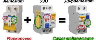
Hello, dear readers! Today we will learn what the time-current characteristic (TCC) is; let’s look at the CTC using the example of fuses and switches. So…
Electric current has one distinctive feature: it can only flow in a closed circuit. If this chain is broken, then its effect immediately ceases. This property is embodied in the operation of maximum current protection based on the use of fuses and circuit breakers.
They are selected in such a way that they can withstand the rated current flowing through them for a long time. This ensures the reliability of power supply to consumers. At the same time, fuses and circuit breakers have protective functions: during emergency conditions in a controlled circuit, they break the dangerous current passing through them.
In this case, two factors are taken into account:
- magnitude of the flowing load current
- duration of its effect
The fuse link burns out from the thermal effect created by the current passing through it.
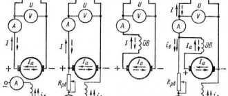
The circuit breaker also takes into account the thermal overheating of the circuit and opens its power contacts due to the operation of the thermal release. At the same time, it contains another device - an electromagnetic release, which reacts to excess electromagnetic energy that occurs even in pulse mode.
More details about the device, principle of operation and operating features of circuit breakers and fuses are described here:
Circuit breaker. Internal structure, characteristics.
Types of fuses. Type, device and design.
The operation of all these devices is judged by certain technical characteristics, which are usually called time-current because they accurately determine the response time of the protection, taking into account its dependence on the excess current ratio of the emergency mode relative to the nominal state.
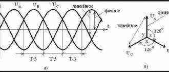
The time current characteristic (TCC) is expressed by graphs in Cartesian coordinates. The ordinate axis is time, counted in seconds, and the abscissa is the ratio of the flowing current in emergency mode I to the nominal value In of the switching device.
Why is a protective characteristic created for a fuse link?
In order to ensure proper operation of the fuse inside the electrical circuit, it is necessary to take into account:
- technical capabilities
- inspection conditions
- appointment
Main parameters of the protective characteristics of the fuse
The graph of fuses tripping at different currents is expressed by a curved line dividing the working coordinate space into two parts:
- working area in which the fuse-link remains intact and reliably ensures the flow of current through the protected circuit
- zone of flow of limit currents, in which the electrical circuit breaks
The first part of the graph is shown in light green, and the second is highlighted in beige.
Protective characteristic of fuse link
The protective characteristic of a fuse link lies on the border of these two zones. In the space of operating currents, the fuse remains intact, and when their values increase above the critical state, it blows out.
The limit current zone is dangerous for equipment and must be turned off as quickly as possible.
The protective characteristic of a fuse link expresses the duration of the period of time from the beginning of the creation of an emergency mode until the moment of its shutdown, presented depending on the excess of the dangerous current over the rated value of the fuse.
The fuse-link is characterized by three types of currents:
- nominal, which it can withstand for an almost unlimited time
- minimum test, under which one can work for more than one hour
- maximum test, which causes it to burn out in less than one hour
The fuse link protects the circuit connected to it from two types of emergency modes:
- overloads with increased loads that turn off with a delay
- short circuits - short circuits requiring the fastest possible elimination
All these modes and types of currents are taken into account when choosing a fuse and fuse link. For this purpose, mathematical relationships have been developed, transformed into graphs and tables in a convenient form.
How is the protective characteristic of a fuse created?
The fuse link can operate as a protection only once. After that it burns out. Therefore, its characterization can only be created indirectly.
To do this, the factory randomly selects a certain number of samples from each batch of finished products. They are used to carry out further electrical tests under the influence of various currents. Based on their results, tables and graphs are compiled that allow one to judge the quality of the released series of fuses.
Purpose of the protective characteristics of the fuse
The fuse link is evaluated by electrical parameters to solve a purely practical problem: ensuring its correct selection in terms of operating and protective properties.
To do this, take into account:
- the value of the operating voltage of the circuit in which the fuse must operate
- limit switchable current at a fuse link that can break it (turn it off)
- the value of the rated current of the fuse, taking into account its load factors and overload detuning.
Without using the protective characteristics of the fuse link, it is impossible to select the correct fuse for its reliable operation in the electrical circuit.
Fuse selection
The choice of fuse is determined by the initial data and features of a particular application [1]:
- Rated current . The circuit's current rating determines the fuse's current rating. To protect against unplanned operations, it is recommended to use a current reserve of 25%. For example, if the rated current of the circuit is 7.5 A, then, taking into account the margin, you should select a fuse based on a current value of 10 A.
- Operating temperature also greatly influences the choice of fuse current rating, so additional margin is necessary for proper operation. For example, if 438 series fuses are expected to operate at a temperature of 75°C, then the margin should be about 15% (see Figure 2).
Let's look at an example. Let's say a 438 series fuse must operate at a temperature of 75°C and a rated current of 1.5 A. Obviously, taking into account points 1 and 2, a fuse with a rating of 1.5 A will not be enough for normal operation. The required current rating with a margin is: 1 .5 A/(0.75 × 0.85) ≈ 2.4 A → 2.5 A (closest rating).
- Operating voltage . The fuse voltage rating must be greater than the maximum possible voltage in the circuit.
- Response speed . Based on the response speed, fuses are divided into five types (FF - super-fast, F - fast, M - semi-slow, T - slow, TT - super-slow). The choice of a specific fuse should be made taking into account the ampere-second ratings provided by the manufacturer.
- Maximum short circuit current . To prevent the fuse from melting or exploding, its breaking capacity must be greater than the maximum short-circuit current.
- Requirements for dimensions, standard size and installation method . There is now a wide range of fuses available for surface mounting, through-hole mounting and for mounting in special holders. The choice of a specific series is determined by the characteristics of each specific application.
- Compliance with standards . The use of a particular fuse is permitted only if it is certified and meets the requirements of established standards. In addition to the GOST R IEC 60127 group of standards, there are other standards. For example, to operate in explosive atmospheres, the fuse must comply with the provisions of GOST 31610.11-2014 (IEC 60079-11:2011) “Explosive atmospheres. Part 11. Equipment with type of explosion protection “intrinsically safe electrical circuit “i” (with Amendment)”.
- Resistance to impulse influences . This point should be discussed in more detail.
This data is sufficient to select a fuse operating in a circuit with a constant or variable sinusoidal current load, if this load does not exceed the current rating of the fuse. However, there are many applications in which the load is pulsed. We are talking about starting currents and various transient processes. In such applications, the fuse must be able to withstand momentary current surges in excess of its current rating without tripping.
To determine whether a fuse will trip or not trip when a given number of current pulses occurs, use the Joule integral I2t, which can be calculated manually or using special utilities. Let's consider each method separately.
How does the time-current characteristic of a circuit breaker work?
The choice of current characteristic time is influenced by:
- design features of built-in protections
- configuration of the selected chart
Influence of the circuit breaker protection design on the shape of its response characteristics
The protective properties of the circuit breaker are ensured by two built-in devices operating on the principles of direct-acting relays. They release the power contacts of the machine when the rated values are exceeded according to the limitation criteria:
- thermal load
- electromagnetic influence
The bimetallic plate of the thermal release perceives the heating of the winding wires. When it is exceeded, it bends, removing the clutch assembly from being held.
Operating principle of thermal release
Under the action of the tension force of the spring, the movable rocker arm, released from its hold, rotates, and its power contacts break the power circuit.
With an electromagnetic release, the power contacts are disconnected due to the knocking out of the spring holding lever by the blow of the pusher, which occurs under the influence of the emergency current.
Operating principle of an electromagnetic release
Unlike a blow-out fuse, both of these devices are designed to be reusable. They allow you to quickly restore circuit shutdowns after preventing abnormal situations.
The operation of the thermal release and electromagnetic cut-off is included in the circuit breaker shutdown algorithm and is comprehensively taken into account when it is triggered during the current characteristic.
Since the temperature of the environment and the bimetallic plate affect the speed of operation of the protections, all measurements are usually carried out at +30 degrees Celsius.
The time graph of the current characteristic for a circuit breaker is a complex line marked with the letters ABC. The upper section AB corresponds to the operation of the thermal release, and its lower part BC corresponds to the electromagnetic cutoff.
Time current characteristic of circuit breaker
Quartz fuses
Quartz fuses are manufactured for voltages of 6, 10 and 35 kV for indoor and outdoor installation. They belong to the group of current-limiting fuses.
Fig.4. Quartz fuse holder type PKT-10
The PKT type fuse holder for voltages 3-35 kV (Fig. 4) is a porcelain or glass tube 1, tightly closed with metal caps 2. Inside the tube there is a fuse-link 3 in the form of one or more thin copper wires connected in parallel. The lower cap contains an indicator that fuse 4 has tripped. The cartridge is filled with fine quartz sand.
The length of the wires and therefore the length of the chuck is determined by the rated voltage. Since the gradient of the recovering electrical strength of the gap in quartz sand is relatively small, the length of the wire must be long. To place it in the chuck, you have to wind the wire helically.
The characteristics of refractory copper inserts (melting point 1080°C) can be improved by soldering drops of tin or lead, the melting point of which is much lower (200 and 327°C, respectively). When the soldering metal melts, it dissolves copper in itself, as a result of which the insert quickly collapses at a temperature significantly lower than the melting point of the main material of the insert.
The properties of the material filling the current-limiting fuse holder significantly affects the operation of the latter.
The filler must meet the following requirements:
- remove heat from the fuse link in normal operating mode;
- do not release gas under the influence of high arc temperature;
- have sufficient electrical strength after a circuit break.
Experience has shown that quartz sand best meets these requirements.
The process of disconnecting the circuit with a current-limiting fuse during a short circuit proceeds as follows. At high current, a thin wire melts and evaporates within fractions of a half-cycle almost simultaneously along its entire length. The arc is lit. Due to the high gas temperature, local pressure is formed in the arc channel (the pressure in the chuck practically does not increase).
Ionized metal particles are ejected radially into the gaps between the quartz sand grains. Here they are quickly cooled and deionized. The arc resistance increases so quickly that the current decreases sharply without reaching its maximum value, and the voltage across the arc gap increases (Fig. 5).
Fig.5. Oscillograms of current and voltage when disconnected by a PKT fuse with a current of 20 kA at a voltage of 6 kV
As can be seen from the oscillogram, the voltage at the fuse terminals exceeds the mains voltage due to the appearance of a self-induction EMF directed in accordance with the mains voltage. Switching overvoltages that occur when the circuit is disconnected by fuses must not exceed the following values:
Rated voltage, kV……3..6..10..20..35
Maximum permissible overvoltage in relation to ground, kV……16..26..40..82..126
To limit overvoltages, various measures are taken: inserts with a stepped cross-section along the length are used, which delays the process of their melting and lengthening of the arc; parallel to the main working inserts, auxiliary inserts with a spark gap are included. In the latter case, when the working inserts melt and the voltage sharply increases, the spark gap of the auxiliary insert breaks through, which also burns out. The maximum voltage decreases.
Current-limiting capacity of quartz fuses
The current-limiting ability of quartz fuses is characterized by the dependence of the largest instantaneous value of the current passed by the fuse on the periodic component of the short-circuit current. The nature of this dependence is shown in Fig. 6.
Fig.6. Current limiting characteristics of quartz fuses
The inclined straight line iud gives the value of the shock current corresponding to the current Iп0 at the ratio X/R=15.7 (Ta=0.05s). Sloping straight lines, designated imax, determine the highest instantaneous values of the current passed by fuses with rated currents of fuse links Inom1, Inom2, Inom3, etc. As can be seen from the figure, current limitation occurs when the switched current Iп0 exceeds a certain minimum value, depending on the rated current of the insert. The smaller the latter, the more noticeable the current-limiting effect of the fuse.
Quartz fuses for protecting PKN type voltage measuring transformers have unlimited breaking capacity and can be installed in switchgear of 6, 10, 35 kV stations and high-power substations. They differ from conventional PC-type quartz fuses in the material of the fuse link, made of constantan wire with a four-stage cross-section. During a short circuit, the melting of the wire occurs in steps. In this case, the resistance of the fourth stage (relatively large cross-section) serves mainly to limit the short-circuit current to values corresponding to the rated shutdown current of PC-type fuses.
Time current characteristic, main parameters of the graph
Taking into account the influence of temperature
In contrast to the protective characteristics of the fuse link of a circuit breaker, the VTX graph is represented by two lines:
- upper, taking into account the activation of protection directly from a cold state of +30О С
- lower, created after restarting, when the machine’s structure did not have time to cool down
The area between these two extreme graphs is highlighted in color. When operating a circuit breaker, be aware that it may be located somewhere within the area shown. In this case, the shutdown time of emergency currents is slightly reduced in a warm state and increases in a cold state. Due to this, a spread of response parameters is created.
The temperature of structural components can have a significant impact on the response time of the machine. This becomes especially relevant when conducting electrical tests that require multiple measurements. To repeat them, it is necessary to provide time for the protection to cool down to +30 degrees.
Division of VTX into zones
Circuit breakers strictly divide the current characteristic time into zones to highlight operational areas:
- inside the first one must ensure reliable flow of operating currents
- and in the second - emergency modes are switched off
Conditional non-trip current line
In order to indicate the first area on the abscissa axis of the graph, the value 1.13 I/I nom was selected. It is called the conditional non-disconnection point. Below these currents, tripping of the circuit breaker should not occur.
When it is reached, circuit breakers with a rated current of up to 63 amperes must turn off after 1 hour, and with higher ratings - after two.
Time current characteristic of circuit breaker
The location of the conditional release point is necessarily indicated on the VTX chart.
Conditional trip current line
The point on the abscissa axis with a value of 1.45 I/I nom is the second limit value of the zone of conditional tripping and non-tipping currents of power contacts.
Time current characteristic of circuit breaker
The point 1.45 I/I nom characterizes the conditional tripping currents; it is also indicated on all VTX graphs. When the load connected to the machine reaches such a value, it must turn off within the time:
- less than 1 hour if rated up to 63 amperes
- no longer than two hours when the rated current exceeds this value of 63 amperes
The above graph shows that for the selected circuit breaker, the emergency shutdown time from a cold state is 1 hour, and when it warms up, it can decrease to 40 seconds.
Gas Generating Fuses
Gas-generating fuses (also called blowing fuses) are designed for outdoor installation in 35 and 110 kV devices.
Fig.2. Cartridge of gas-generating fuse type PVT-35
Figure 2 shows a PVT-35 type fuse holder (exhaust fuse for protecting power transformers and 35 kV lines). The cartridge body 1 contains tubes 2 and 3 made of vinyl plastic, connected to each other by a steel pipe 4, as well as a fuse-link 5, attached at one end to the current-carrying rod 6, and at the other to a flexible conductor 7 with a tip 8.
Fig.3. Gas-generating fuse type PVT-35
The cartridge is installed on the base of the fuse (Fig. 3), consisting of a base 1, two support insulators 2 with heads - the top 3 and the bottom 4 with clamps for fastening the conductors. A contact knife 5 is mounted on the lower head, equipped with a spring and engaged with the tip of the cartridge. When the fuse link burns out, the contact knife is released and, reclining under the action of a spring, pulls the flexible conductor along with it. Under the action of the arc, the walls of the vinyl plastic tubes emit gas, the pressure in the cartridge increases and the arc is extinguished in the gas flow flowing from the cartridge through the lower hole, as well as through the valve of the side hole of the pipe. When the fuse is triggered, it produces a sound effect similar to a gun shot. The flexible conductor is ejected from the socket. An air gap is created between the contact blade and the end of the tube, providing insulation at the break point. The rated disconnecting current of the PVT-35 type fuse is 3.2 kA.
Practical application of VTX parameters
Analysis of the use of the time-current characteristics of circuit breakers based on the conditional tripping currents of power contacts makes it possible to take into account the duration of overloads in the connected electrical circuit. This is important to do because they can damage the equipment.
For example, when choosing a machine with a rating of 16 amperes and keeping it in a cold state, a conditional trip current of 1.45∙16 = 23.2 amperes will act on the connected electrical wiring for one hour. This time is quite enough to overheat the insulation of copper wires with a cross-section of 1.5 mm square and disable it, creating conditions for a fire. And cases of protection of such conductors, and even 2.5 mm sq. aluminum conductors, by such automatic devices are still often encountered in practice.
To eliminate such situations, it is recommended to carefully analyze the time-current characteristics of circuit breakers in relation to the load connected to them. To facilitate their selection, a table of correspondence between rated currents and cross-sectional areas of copper conductors of cables and wires has been created.
Table for selecting circuit breakers by rated current and cross-section of cable line cores
Manufacturers of circuit breakers test all their products for compliance with accepted standards. The basic requirements for automatic machines are set out in GOST R 50345-2010. However, in some areas, the current characteristics of each plant may differ slightly. This feature must be taken into account when choosing a specific model and testing it.
Regulations
Safety is a critical factor both in production processes and in people's daily lives. Therefore, fuses must necessarily meet the stringent requirements of existing safety standards. Any official manufacturer indicates what safety standards its products meet.
Different countries have their own regulatory bodies and regulations. For the domestic market, IEC standards are primarily of interest. In particular:
- GOST R IEC 60127-1-2005 Miniature fuses. Part 1: Terminology for fuses and general requirements for miniature fuse links;
- GOST IEC 60127-2-2013 Miniature fuses. Part 2. Tubular fuse links;
- GOST IEC 60127-3-2013 Miniature fuses. Part 3. Subminiature fusible links;
- GOST IEC 60127-4-2011 Miniature fuses. Part 4. Universal modular fuse-links for volumetric and surface mounting;
- GOST 30801.5-2012 (IEC 60127-5:1989) Miniature fuses. Guide to Certification of Miniature Fuse Links;
- GOST IEC 60127-6-2013 Miniature fuses. Part 6. Fuse holders with miniature fuse link.
According to GOST R IEC 60127-1-2005, a fuse is a device that, by melting one or more of its parts having a certain design and dimensions, opens the circuit in which it is connected, interrupting the current if it exceeds a specified value for a certain time. The same standard presents the characteristics of fuses and general requirements for them.
Types of time-current characteristics of circuit breakers
Automatic protection can be created for different purposes depending on operating conditions. According to these indicators, their performance characteristics graphs have different response time limits. This allows them to be tuned according to selectivity and avoid false equipment shutdowns. Circuit breakers are produced for domestic or industrial use.