Motion sensor device
The design of the sensor contains two parts - a fixed one, which is attached to the surface, and a movable one. The moving part has two degrees of freedom and can rotate 30-400 in horizontal and vertical planes.
When disassembled, the LX-02 motion sensor looks like this:
View of boards from the parts side
View from the back side (from the soldering side):
View of the motion sensor boards from the solder side
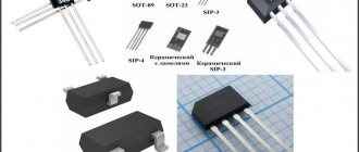
The device uses the following main parts:
- The chip is LM324, these are four operational amplifiers in one package. The datasheet can be downloaded here: • LM324,224,2902 Operational Amplifiers.pdf / , pdf, 134.11 kB, downloaded: 3882 times./
- motion sensor – PIR D203S or 1VY7015
- transistor type S9013 - bipolar medium power. The datasheet can be downloaded here: • S9013 / , pdf, 62.29 kB, downloaded: 2044 times./
- relay SHD-24VDC-FA.
On the side of the microcircuit key there is a light control, next to it there is an on-time control.
Configuring and adjusting device settings
In order for the device to correctly respond to movement and not react to interference, the movement of pets or branches outside the window, it is important not only to install it correctly, but also to configure it correctly
Viewing angle
Some devices allow you to control the viewing angle using a special switch on the device body. This makes it possible to reduce or, conversely, increase the angle of the controlled zone by the motion sensor for correct operation. Those devices that do not have viewing angle adjustment can be adjusted by turning them in the desired direction or using a wall as a limiter. Craftsmen also resort to using electrical tape, artificially limiting the sensor’s view by taping its scanning screen in the right places.
Sensitivity (SENS)
This switch allows you to reduce the number of false alarms from pets, tree branches outside the window and other factors. Adjustment for this factor begins with the minimum value of the switch, followed by an increase to the desired value. All this is done experimentally with mandatory testing.
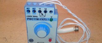
Shutdown delay (TIME)
The ability to configure the delay depends on the specific device and can range from 5 seconds to 30 minutes. This parameter is adjusted based on user preferences and the purpose of the room or lighting. It works as follows: when motion is detected, the lighting turns on and then turns off only after the configured delay on the device has expired.
Light level (LUX/DAY LIGHT)
Setting this parameter is made to adjust the switching on of the lighting device at a given illumination. That is, it will turn on only if movement is detected at the adjusted light level. If the illumination in the room is higher, the device will not turn on. The adjustment is made from the minimum value, gradually increasing to the required value.
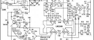
Motion sensor circuits
The sensor circuit looks something like this.
Diagram of motion sensor LX-02 and analogues
Here is another similar scheme, but simpler. This is a security sensor circuit. I express my gratitude to the source – www.guarda.ru.
Motion Sensor. Scheme 2
In different sensor models, the circuit may vary slightly, but the operating principle is the same. Briefly it can be described as follows.
The signal from the pyro sensor (most often used is 1vy7015) goes to the amplifier, then the comparator operates, from the output of which the signal goes through the transistor to the relay coil. The relay turns the load on and off with its contacts.
The 4 microcircuits shown in the diagram should not be misleading - in fact, this is one microcircuit, in the case of which there are 4 operational amplifiers with a common power supply.
The third diagram is given at the end of the article.
What is a pyromodule or PIR (motion) Sensor?
The abbreviation PIR or PIR stands for Passive Infra-Red or Passive Infrared.
A pyromodule, or PIR-sensor, is a device that converts changes in the intensity of infrared radiation into electric current. The operation of the pyromodule is based on the pyrostatic effect, which occurs in some crystalline materials when the temperature changes. A change in the temperature of the sensor can be caused by infrared radiation.
Since the change in the electric field of crystalline dielectrics is compensated by the field of free electric charges, the field can be recorded only when it changes. This remarkable property of sensors built on the basis of pyroelectrics allows one to track minute changes in radiation intensity that occur over relatively short periods of time, while the smoothly changing temperature of the pyroelectric module itself does not affect the measurement results.
To protect against interference and other harmful influences, the pyro-sensor is enclosed in a sealed metal case, which is equipped with a window. The window is covered with an infrared notch filter that transmits light in a narrow range of radiation, the spectral characteristic hump of which is in the region of 10 μm (1 * 104 nm). The picture shows pyromodules: the Soviet “PM-4” and the imported “D203S”.
In imported pyro modules, behind the infrared filter there is not only the pyro sensor itself, but also an amplifier based on a low-noise unipolar (field-effect) transistor. The picture shows the connection diagram and pinout of the foreign-made pyromodule “PIR D203S”.
To connect Soviet-made pyromodules, a field-effect transistor had to be installed additionally. The picture shows the connection diagram and pinout of the Soviet-made PM-4 pyromodule.
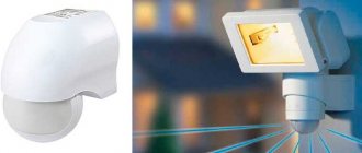
Once upon a time, pyromodules were a secret development of the military-industrial complex and were installed in TGS Thermal Homing Heads (Heatseeker) of missiles and other combat devices.
But now pyromodules are widely used in civilian technology. They are mainly used as motion detectors in alarm and lighting control systems. The picture shows one of these Feron LX20/SEN5 sensors, designed to control lighting.
Connecting a motion sensor
Connecting a motion sensor requires a little more skill than connecting a regular switch. By mixing up the sensor leads, you can burn both the sensor itself and the electrical wiring. Especially if it is not properly protected.
I had this happen when the instructions indicated certain wire colors, but in reality they were different.
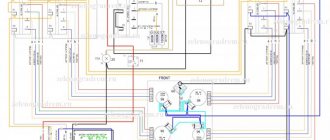
The motion sensor and light sensor (photo relay, or twilight relay) are connected in exactly the same way, so in the diagram below the source of influence is indicated by light.
Pins for connecting motion sensor and light sensor
Motion and light sensor connection diagram.
As you can see, this connection diagram is no different from the diagram for turning on a light bulb through a regular switch. The only difference is that the neutral wire is also involved in the connection, and that the switch is acted upon by a human hand, and the sensor is acted upon by movement or light.
How to connect a motion sensor is also shown in the diagram in the instructions (below).
The diagram also shows the colors of the wires. Also, terminal designations are usually stamped on the housing near each terminal.
Color of leads for connecting LX sensor:
- brown (black) – phase input (to turn on the lighting and power the internal circuit)
- blue (green, blue) – zero for powering the electronic circuit of the sensor, not used for powering lighting.
- red – phase output (load connection)
The load (light bulb) is connected to zero and the output.
It is worth noting that such color marking is not mandatory for the manufacturer. Even from the same manufacturer, the same terminals may have different wire colors. Therefore, you need to refer to the instructions, and if in doubt, disassemble the sensor and look at the connection of the wires on the board.
Where is it used?
As already mentioned, the main area of application of motion sensors is home automation, the creation of control and surveillance systems in buildings, and security. Using such sensors you can organize:
- automated lighting through motion sensors to turn on the lights and corresponding controllers/switches;
- control of the climate system by triggers;
- recognition of unauthorized access to premises, and so on.
Devices like these help you save money. Thus, their inclusion in a complex of automatic control of light and air conditioning reduces a company’s or homeowner’s costs for light by 70%, and energy consumption by up to 40%.
Motion sensors are used in:
- aircraft industry;
- defense industry;
- development;
- automotive industry;
- development of consumer electronics, and so on.
Use in security
If such a sensor is included in the remote control complex, when motion is detected, it will turn on the siren and also send an alarm to the dispatcher's console. Having received it, the security organization will be able to send a rapid response team to the site.
If the device operates as part of home security, smart home and similar systems, it will be able to send a notification to the owner via SMS, email or other means. Some solutions can even make calls to one or more “trusted” phone numbers.
Other possible sensor functions include:
- turning on video surveillance;
- locking the locks on the premises;
- blackout of equipment;
- turning on (or, conversely, turning off) the light;
- any other function that can be implemented by a specific set of hardware and software.
Lighting automation
The sensor can be intended for a street or indoor lighting system. Depending on the location, it is capable of giving commands to turn off the light and turn it on, as well as change the level and color of illumination (with or without a delay).
In general, the sensor sends a signal to the lighting controller, which performs further actions according to the scripts and programs embedded in it, activates switches, and so on. But there are also switches with already built-in sensitive components. They are often used as street motion sensors to turn on lights.
Solutions for controlling “smart lamps” and RGB LED strips are common.
Climate systems
Appropriately configured climate control changes power, temperature and other parameters based on a sensor signal. For this:
- the sensor transmits information to the controller about the detected movement (as well as its termination);
- the central unit launches a sequence of commands, including climate control, turning it off or changing modes.
For example, if a signal is received from a room sensor in cold weather, the controller will order the heating thermostats to increase heat to quickly create comfortable conditions. And if there is no movement in the operating area in the summer, the device will force the air conditioner to reduce power.
Instructions for the motion sensor
Since this article discusses the LX-02 (SEN15) model, instructions for this sensor are given below.
Instructions for motion sensor LX-02
That's basically all I wanted to tell you about the device and circuit of the motion sensor .
By the way, I have several more articles regarding this topic:
- Description, application and parameters
- Installation of street sensors over large areas
- Various advanced switching schemes
- LED lamp
The topic of sensor repair is covered in the article Do-it-yourself motion sensor repair. Step by step guide. A motion sensor circuit based on a specialized LP8072C microcircuit is also shown and discussed there.
Connecting HC-SR501 to Arduino Uno
For connection to a microcontroller or directly to a relay, the HC-SR501 has three pins. We connect them to Arduino according to the following scheme:
| HC-SR501 | GND | VCC | OUT |
| Arduino Uno | GND | +5V | 2 |
Schematic diagram
Layout appearance
Program
As already mentioned, the digital output of the HC-SR501 sensor generates a high signal level when triggered. Let's write a simple program that will send “1” to the serial port if the sensor saw movement, and “0” otherwise.
const int movPin = 2 void setup() { Serial.begin(9600); pinMode(movPin, INPUT); } void loop(){ int val = digitalRead(movPin); Serial.println(val); delay(100); }
We load the program onto Arduino and check the operation of the sensor. You can tweak the sensor settings and see how this affects its operation.
Another sensor circuit
Reader Alexander from Korolev in December 2014 sent another motion sensor circuit, which he copied from the board with his own hands. Photo is also attached.
Motion sensor circuit 3
And here are oscillograms explaining the operation of the circuit:
Oscillogram 1 of the sensor circuit operation
Oscillogram 2 of motion sensor operation
Motion sensor board. Board model – 94vo-d
Alexander, thank you! Good luck in job!
Construction and details
All design parts, except for the temperature sensor, are assembled on a printed circuit board measuring 45x85mm.
Printed circuit board of the coffee maker control unit assembly.
The temperature sensor is made on the basis of a germanium diode, which is inserted into a mount made of tin from a tin can.
The temperature sensor is fixed to the body of the coffee maker using silicone sealant. A small drop of KPT-8 thermal paste is applied between the tin bracket and the body. The sensor is connected using an MGTF wire in fluoroplastic insulation.
All the plumbing work came down to drilling just two holes in the coffee maker stand.
Two power wires, one load control wire and two temperature sensor wires were laid through these holes. As you can see, the maintainability of the control unit is ensured.
To protect the pyromodule eye, I used a polypropylene plate, which I cut from the piston of a disposable syringe.
Interestingly, the narrow spectrum of infrared radiation in which the pyromodule operates is blocked by ordinary glass and plexiglass, although it is transmitted by many types of plastics, including nylon (polyethylene), polypropylene, etc.
Here's how it works. Video in HD resolution (1280x720px).
Appearance of the motion sensor
A couple more photos of what the motion sensor board might look like when disassembled.
Motion sensor board. Solder side
Motion sensor board. View from the parts
If anything is not clear or you have something to add, ask and write in the comments. If you are interested in what I will publish next on my blog SamElectric.ru, subscribe to receive new articles.
Setting up the HC-SR501
In this tutorial we will use the HC-SR501 module. This module is very common and is used in many DIY projects due to its low cost.
The sensor has two variable resistors and a jumper for setting the mode. One of the potentiometers adjusts the sensitivity of the device. The larger it is, the further the sensor “sees”. Sensitivity also affects the size of the detected object. For example, you can exclude a dog or cat from triggering.
The second potentiometer regulates the response time T. If the sensor detects movement, it generates a positive pulse of length T .
Finally, the third control is a jumper that switches the sensor mode. In position L , the sensor counts T from the very first operation. Let's say we want to control the light in the bathroom. Entering the room, a person will trigger the sensor, and the light will turn on exactly for the time T. At the end of the period, the output signal will return to its original state, and the sensor will give the next response.
In position H, the sensor starts timing T every time motion is detected. In other words, any human movement will cause the countdown timer T . By default, the jumper is in the H .