15 594
Burykin Valery Ivanovich
Current generator
and
a voltage generator
. What is the difference? What is a Current Generator and what are its areas of application.
***
For work, it was necessary to find some clear description of what a current generator is (current stabilizer, current source)
, its areas of application and calculation examples. We couldn't find anything acceptable.
I had to start writing an article answering these questions myself.
And yet, we had to replace the generally accepted designations “delta” and “infinity” with words. Unfortunately, instead of them, when you try to read the text, question marks are displayed.
02/28/2012
***
The first thing we need to understand is what the differences are between a current generator and a voltage stabilizer.
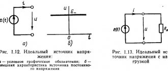
What is an ideal current source
A real current source is an object in which complex processes occur. To simplify things, it is advantageous to use an ideal abstraction. Its peculiarity lies in the fact that it has only strictly defined properties. This approach makes it possible to simplify calculations and at the same time ensure that data is obtained with the necessary accuracy.
Not only a current source, but also a voltage source can be ideal. In the first case, an active element is considered that provides the required electric current between its terminals. In this case, it is customary to consider the current to be absolutely independent of voltage. It can have any predetermined shape. An ideal IT has an infinitely large internal resistance.
An ideal voltage source provides a potential difference at its terminals that is independent of the electric current flowing in the circuit. This source has no internal resistance. In reality, any EMF source has such resistance, and this is the difference between a real EMF source and an ideal one.
The relationship between the voltage at the IT terminals and the electric current is usually called the external characteristic. Its graph for an ideal IN is expressed as a straight line parallel to the current axis. The external characteristic of an ideal IT is a parallel straight line with the stress axis.
It is important to note that the idealized representation of power supplies has significant drawbacks. As an example, consider the following situation. Let's imagine a circuit with an ideal current source in which only the load is present.
If you increase the resistance value, the power released by the resistor will also increase. In this idealized situation, infinite power can be obtained in this way. But in practice this is impossible, since the power of any energy source is a finite quantity.
A distinction should be made between uncontrolled (independent) sources and controlled (dependent) sources. An uncontrolled ideal current source has parameters that do not depend on what happens in the electrical circuit. The characteristics of the controlled device are a function of the electric current or voltage of a certain section of the circuit.
In practice, controlled current sources are devices with four terminals. A control current or voltage is supplied to one pair of terminals, and ideal parameters are taken from the other two terminals, which are a function of the input characteristic. There are four types of such nodes:
- A voltage source that is controlled by voltage. This source is abbreviated as INUN. This is option (a). The input signal goes to the terminals located on the left. The voltage at the terminals on the right is a function of the control voltage.
- Voltage source controlled by current (INUT). Diagram (b) shows that a control current is supplied to the input terminals, and a voltage is removed on the right, which is a function of the current.
- A source controlled by a current that is a function of the control voltage (ITUN). Option (c).
- A source that is controlled by a current that is a function of the control current (ITUT). Option (d).
Dependent Sources
As the name suggests, dependent sources produce an amount of voltage or current that depends on some other voltage or current. Dependent sources are also called controlled sources
. Dependent sources can be further classified into the following two categories −
- Dependent voltage sources
- Dependent current sources
Dependent voltage sources
A dependent voltage source produces voltage across its two terminals. The magnitude of this voltage depends on some other voltage or current. Hence dependent voltage sources can be further classified into the following two categories −
- Voltage-dependent voltage source (VDVS)
- Current dependent voltage source (CDVS)
Dependent voltage sources are represented by "+" and "-" signs within a diamond shape. The magnitude of the voltage source can be represented outside of the diamond shape.
Dependent current sources
A dependent current source produces current. The magnitude of this current depends on some other voltage or current. Hence, dependent current sources can be further classified into the following two categories −
- Voltage dependent current source (VDCS)
- Current Dependent Current Source (CDCS)
Dependent current sources are represented by an arrow inside a diamond. The magnitude of the current source can be represented outside of the diamond shape.
We can observe these dependent or controlled sources in equivalent transistor models.
How does an ideal source differ from a real one?
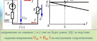
When an ideal current source is considered, it is assumed that it has an infinitely large internal resistance. Therefore, its current is not affected by those parameters of the external electrical circuit on which the voltage at the terminals of the device depends. A real battery behaves differently: the greater the current in it, the smaller the potential difference.
This can be explained as follows. Current represents the ordered movement of charges. When a current source is connected to an electrical circuit, electrons move from one terminal to another. If the current in the circuit is strong, the electromotive force does a worse job of moving carriers inside the battery. This leads to a decrease in the potential difference.
When electrical appliances are connected to the electrical network, they create a load for it. If it is significant, then there is a change in the voltage and current with which the equipment operates.
When an ideal source is considered, the current strength remains independent of voltage. In most cases, we are talking about a constant current strength, although it can vary in accordance with an arbitrary, predetermined function. The presence of a constant characteristic makes it possible to simplify the calculation of the circuit.
In reality, the current flowing through the circuit depends on the load. If it decreases, the current strength can increase sharply. This effect is called short circuiting. To avoid this, fuses are used. If the current is too high, a large amount of thermal energy is released. This causes the fuse to melt and the circuit to break.
A sudden increase in current may cause an accident, but its excessive decrease can also cause an emergency. For example, it may turn out that the current strength is insufficient for normal operation of the device.
Source conversion technique
We know that there are two practical sources: a voltage source and a
current
. We can transform (convert) one source to another based on requirements, solving network problems.
The technique of converting one source to another is called source conversion technique
. Below are two possible source transformations:
- Practical voltage source into practical current source
- Practical current source into practical voltage source
Practical voltage source into practical current source
The conversion of a practical voltage source to a practical current source is shown in the following figure.
Practical voltage source
consists of a voltage source (VS) connected in series with a resistor (RS). This can be converted into a practical current source as shown in the figure. It consists of a current source (IS) in parallel with a resistor (RS).
The value of IS will be equal to the ratio of VS and R S. Mathematically, this can be represented as
$$I_S = \frac {V_S}{R_S}$$
Practical current source into practical voltage source
The conversion of a practical current source to a practical voltage source is shown in the following figure.
A practical current source consists of a current source (IS) in parallel with a resistor (RS). This can be converted into a practical voltage source as shown in the figure. It consists of a voltage source (VS) connected in series with a resistor (RS).
The value of VS will be equal to the product of IS and R S. Mathematically, this can be represented as
$$ V_S = I_S R_S $$
How ideal sources are used
Ideal circuits are sometimes used when accurate calculations of real electrical devices are required. In such situations, substitution is made according to strictly defined rules. It is important to follow them so that the result obtained has the required accuracy. Such a replacement is not permissible in all cases, but for a very limited range of electric currents and voltages.
For example, controlled sources have found use in constructing equivalent circuits for semiconductor devices such as transistors. In particular, ITUN can be seen in the equivalent circuit of a field-effect transistor.
It is impossible to build an ideal IT with infinitely large internal resistance. But in practice, devices based on transistors can be used. Their internal resistance reaches quite large values. Using such current sources, circuits of differential and operational amplifiers and digital-to-analog converters are built.
Excerpt characterizing the Current Source
A few minutes later, Prince Andrei called, and Natasha came in to see him; and Sonya, experiencing an emotion and tenderness she had rarely experienced, remained at the window, pondering the extraordinary nature of what had happened. On this day there was an opportunity to send letters to the army, and the Countess wrote a letter to her son. “Sonya,” said the Countess, raising her head from the letter as her niece walked past her. – Sonya, won’t you write to Nikolenka? - said the countess in a quiet, trembling voice, and in the look of her tired eyes, looking through glasses, Sonya read everything that the countess understood in these words. This look expressed pleading, fear of refusal, shame for having to ask, and readiness for irreconcilable hatred in case of refusal. Sonya went up to the countess and, kneeling down, kissed her hand. “I’ll write, maman,” she said. Sonya was softened, excited and touched by everything that happened that day, especially by the mysterious performance of fortune-telling that she just saw. Now that she knew that on the occasion of the renewal of Natasha’s relationship with Prince Andrei, Nikolai could not marry Princess Marya, she joyfully felt the return of that mood of self-sacrifice in which she loved and was accustomed to living. And with tears in her eyes and with the joy of realizing a generous deed, she, interrupted several times by tears that clouded her velvety black eyes, wrote that touching letter, the receipt of which so amazed Nikolai. At the guardhouse where Pierre was taken, the officer and soldiers who took him treated him with hostility, but at the same time with respect. One could still feel in their attitude towards him doubt about who he was (whether he was a very important person), and hostility due to their still fresh personal struggle with him. But when, on the morning of another day, the shift came, Pierre felt that for the new guard - for the officers and soldiers - it no longer had the meaning that it had for those who took him. And indeed, in this big, fat man in a peasant’s caftan, the guards of the next day no longer saw that living man who so desperately fought with the marauder and with the escort soldiers and said a solemn phrase about saving the child, but saw only the seventeenth of those being held for some reason, by by order of the highest authorities, the captured Russians. If there was anything special about Pierre, it was only his timid, intently thoughtful appearance and the French language, in which, surprisingly for the French, he spoke well. Despite the fact that on the same day Pierre was connected with other suspected suspects, since the separate room he occupied was needed by an officer. All the Russians kept with Pierre were people of the lowest rank. And all of them, recognizing Pierre as a master, shunned him, especially since he spoke French. Pierre heard with sadness the ridicule of himself. The next evening, Pierre learned that all of these prisoners (and probably himself included) were to be tried for arson. On the third day, Pierre was taken with others to a house where a French general with a white mustache, two colonels and other Frenchmen with scarves on their hands were sitting. Pierre, along with others, was asked questions about who he was with the precision and certainty with which defendants are usually treated, supposedly exceeding human weaknesses. where he was? for what purpose? etc. These questions, leaving aside the essence of the life matter and excluding the possibility of revealing this essence, like all questions asked in courts, had the goal only of setting up the groove along which the judges wanted the defendant’s answers to flow and lead him to the desired goal, that is, to the accusation. As soon as he began to say something that did not satisfy the purpose of the accusation, they took a groove, and the water could flow wherever it wanted. In addition, Pierre experienced the same thing that a defendant experiences in all courts: bewilderment as to why all these questions were asked of him. He felt that this trick of inserting a groove was used only out of condescension or, as it were, out of politeness. He knew that he was in the power of these people, that only power had brought him here, that only power gave them the right to demand answers to questions, that the only purpose of this meeting was to accuse him. And therefore, since there was power and there was a desire to accuse, there was no need for the trick of questions and trial. It was obvious that all answers had to lead to guilt. When asked what he was doing when they took him, Pierre answered with some tragedy that he was carrying a child to his parents, qu'il avait sauve des flammes [whom he saved from the flames]. – Why did he fight with the marauder? Pierre replied that he was defending a woman, that protecting an insulted woman is the duty of every person, that... He was stopped: this was not getting to the point. Why was he in the yard of the house on fire, where witnesses saw him? He replied that he was going to see what was happening in Moscow. They stopped him again: they didn’t ask him where he was going, and why he was near the fire? Who is he? They repeated the first question to him, to which he said that he did not want to answer. Again he replied that he could not say that. - Write it down, this is not good. “It’s very bad,” the general with a white mustache and a red, ruddy face told him sternly. On the fourth day, fires started on Zubovsky Val. Pierre and thirteen others were taken to Krymsky Brod, to the carriage house of a merchant's house. Walking through the streets, Pierre was choking from the smoke, which seemed to be standing over the entire city. Fires were visible from different directions. Pierre did not yet understand the significance of the burning of Moscow and looked at these fires with horror. Pierre stayed in the carriage house of a house near the Crimean Brod for four more days, and during these days he learned from the conversation of the French soldiers that everyone kept here expected the marshal's decision every day. Which marshal, Pierre could not find out from the soldiers. For the soldier, obviously, the marshal seemed to be the highest and somewhat mysterious link in power. These first days, until September 8th, the day on which the prisoners were taken for secondary interrogation, were the most difficult for Pierre. On September 8th, a very important officer entered the barn to see the prisoners, judging by the respect with which the guards treated him. This officer, probably a staff officer, with a list in his hands, made a roll call of all the Russians, naming Pierre: celui qui n'avoue pas son nom [the one who does not say his name]. And, looking indifferently and lazily at all the prisoners, he ordered the guard officer to dress them decently and tidy them up before leading them to the marshal. An hour later, a company of soldiers arrived, and Pierre and thirteen others were taken to the Maiden Field. The day was clear, sunny after the rain, and the air was unusually clean. Smoke did not settle down like on the day when Pierre was taken out of the guardhouse at Zubovsky Val; smoke rose in columns in the clear air. The flames of the fires were nowhere to be seen, but columns of smoke rose from all sides, and all of Moscow, everything that Pierre could see, was one conflagration. On all sides one could see vacant lots with stoves and chimneys and occasionally the charred walls of stone houses. Pierre looked closely at the fires and did not recognize familiar quarters of the city. In some places, surviving churches could be seen. The Kremlin, undestroyed, loomed white from afar with its towers and Ivan the Great. Nearby, the dome of the Novodevichy Convent glittered merrily, and the bell of the Gospel was especially loudly heard from there. This announcement reminded Pierre that it was Sunday and the feast of the Nativity of the Virgin Mary. But it seemed that there was no one to celebrate this holiday: everywhere there was devastation from the fire, and from the Russian people there were only occasionally ragged, frightened people who hid at the sight of the French.
Comparison of voltage and current sources
Most power sources (grid and battery) are modeled as voltage sources. ideal
a voltage source produces no energy when it is loaded with an open circuit (i.e., infinite resistance), but approaches infinite energies and currents when the load resistance approaches zero (a short circuit). Such a theoretical device would have zero output impedance in series with the source. A real voltage source has very low but non-zero internal resistance and output resistance, often much less than 1 ohm.
Conversely, a Current source provides constant current as long as the load connected to the source terminals has a low enough impedance. An ideal current source would provide no short circuit energy and would approach infinite energy and voltage as the load resistance approaches infinity (open circuit). An ideal
The current source has an infinite output impedance in parallel with the source.
And the real world
current source has a very high but finite output impedance. In the case of transistor current sources, the total resistance is several units. megohms (at low frequencies) typical.
Since there are no ideal sources of either variety (all real-life examples have finite and non-zero source impedance), any current source can be considered a voltage source with the same
The source resistance is the opposite. Voltage sources and current sources are sometimes called counterparts of each other, and any non-ideal source can be converted from one to the other by applying Norton's Theorem or Thevenin's Theorem.
Electronics as art: electric current
Don't get in. Will kill! (With)
The average literacy of the population in the field of electronics and electrical engineering leaves much to be desired. Maximum, solder the circuit, but how it works is a dark forest. Unfortunately, all Russian-language textbooks are full of formulas and integrals; they will make anyone sleepy. In English-language literature, things are somewhat better. There are quite interesting publications, but the stumbling block here is the English language. I will try to present the basic concepts of electrical engineering as accessible as possible, in a free style, not from engineer to engineer, but from person to person. The knowledgeable reader may also find some interesting points for himself.
Electricity
The paths of electric current are mysterious. (c) thoughts from the Internet
Not really.
Everything can be described in one way or another using a mathematical model, simulation, or even a quick estimate on a piece of paper, and some unique people do this in their heads. Whichever is more convenient for you. In fact, the epigraph of this chapter was born from ignorance of what electric current is. Electric current is characterized by several parameters. Voltage U and current I. Of course, we all remember the definitions from physics, but few people understand their meaning. I'll start with tension. Potential difference or work to move a charge, as they write dryly and uninterestingly in textbooks. In fact, voltage is always measured between two points. It characterizes the ability to create an electric current between these two points. Let's call these points a voltage source. The higher the voltage, the higher the current. Less voltage means less current. But more on that later. What is current? Imagine an analogy: a river bed is wires, electric current is the speed of water flow in the river. Then the voltage here is the difference in height between the starting point of the river and the ending point. Or voltage is a pump driving water if the river flows in one plane. Such analogies at the initial stages are very helpful in understanding what is happening in the electrical circuit. But in the end, it's better to give them up. It is better to think of current as a flow of electrons. The amount of charge moved per unit time. Of course, the textbooks say that electrons move at a speed of several centimeters per minute and that only the electromagnetic field matters, but let’s forget about that for now. So, current can be understood as the movement of electric current, i.e. charge. Charge carriers, electrons, are negatively charged and move from a negative potential to a positive one, while the electric current has a direction from a positive potential to a negative one, from plus to minus, this is customary for convenience and this is how we will use it in the future, forgetting about the charge of the electron.
Of course, the current itself will not appear, you need to create a voltage between two points and you need some kind of load to flow current through it, connected to these two points. It is very useful to know the property that for current to flow you need two conductors: direct, to the load, and reverse, from the load to the source. For example, if the conductors of the voltage source are not short-circuited, then there will be no current.
What is a voltage source? Let's imagine it in the form of a black box with at least two terminals for connection. The simplest examples from real life: an electrical outlet, a battery, an accumulator, etc.
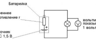
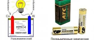
An ideal voltage source has a constant voltage when any current flows through it. What happens if you close the terminals of an ideal voltage source? An infinitely large current will flow. In reality, voltage sources cannot deliver an infinitely large current because they have some resistance. For example, the wires in a 220V power outlet from the outlet itself to the substation have resistance, albeit small, but quite noticeable. Wires from substations to power plants also have resistance. We must not forget about the impedance of transformers and generators. Batteries have internal resistance due to an internal chemical reaction that has a finite rate of occurrence.
What is resistance? In general, this topic is quite extensive. Perhaps I will describe it in one of the next chapters. In short, this is a parameter connecting current and voltage. It characterizes how much current will flow when voltage is applied to this resistance. If we speak in a “water” analogy, then resistance is a dam in the path of a river. The smaller the hole in the dam, the greater the resistance. This relationship is described by Ohm's law: . As they say: “If you don’t know Ohm’s law, stay at home!”
Knowing Ohm's law, without sitting at home, having any current source with a given voltage and resistance in the form of a load, we can very accurately predict what current will flow. Real voltage sources have some kind of internal voltage and supply a certain finite current, called short circuit current. At the same time, batteries and accumulators also discharge over time and have nonlinear internal resistance. But let’s forget about that for now, and here’s why. In real circuits, it is more convenient to carry out analysis using momentary instantaneous values of voltage and current, so we will consider the voltage sources to be ideal. Except for the fact when you need to calculate the maximum current that the source is capable of delivering.
About the “water” analogy of electric current. As I already wrote, it is not very true, since the speed of the river before and after the dam will be different, and the amount of water before and after the dam will also be different. In real circuits, the electric current flowing into the resistor and flowing out of it will be equal to each other. The current in the forward wire, to the load, and in the return wire, from the load to the source, is also equal to each other. The current doesn’t come from anywhere and doesn’t go anywhere; the amount that “flows” into a circuit node is the same amount that “flows out,” even if there are several paths. For example, if there are two paths for current flow from a source, then it will flow along these paths, and the total current of the source will be equal to the sum of the two currents. And so on. This is an illustration of Kirchhoff's law. It's very simple.
There are also two more important rules. When connecting elements in parallel, the voltage in each element is the same. For example, the voltage across resistor R2 and R3, in the figure above, are the same, but the currents can be different if the resistors have different resistances, according to Ohm's law. The current through the battery is equal to the current through resistor R1 and equal to the sum of the currents through resistors R2 and R3. When connected in series, the voltages of the elements add up. For example, the voltage that the battery produces, i.e. its EMF is equal to the voltage across resistor R1 + voltage across resistor R2 or R3.
As I already wrote, voltage is always measured between two points. Sometimes in the literature you can find: “The voltage at such and such a point.” This means the voltage between this point and the zero potential point. You can create a point of zero potential, for example, by grounding the circuit. Usually the circuit is grounded at the most negative potential near the power source, for example, as in the figure above. True, this does not always happen, and the use of zero is quite conditional, for example, if we need bipolar power +15 and -15 volts, then we need to “ground” not -15V, but the potential in the middle. If we ground -15V, then we get 0, +15, +30V. See pictures below.
Grounding is also used as a protective or working ground. Protective grounding is called grounding. If the insulation of the circuit is broken in some other area other than the ground, then a large current will flow through the neutral wire and a protection will be triggered, which will turn off part of the circuit. We must provide protection in advance by placing a circuit breaker or other device in the path of current flow.
Sometimes it is impossible or impossible to “ground” a circuit. Instead of earth, the term common point or zero is used. Voltages in such circuits are indicated relative to a common point. Moreover, the entire circuit is relative to the ground, i.e. zero potential can be located anywhere. See picture.
Typically, Xv is close to 0 volts. Such ungrounded circuits, on the one hand, are safer, because if a person touches the circuit and the ground at the same time, no current will flow, because there is no reverse path for current flow. Those. the circuit will become “grounded” through the person. But on the other hand, such schemes are tricky. If the isolation of the circuit from the ground is suddenly broken at any point, we will not know. Which can be dangerous at high voltages Xv.
In general, land is a rather broad and vague term. There are a lot of terms and names for ground, depending on where to “ground” the circuit. Ground can be understood as both protective ground and working ground (based on the flow of current through it during normal operation), both signal ground and power ground (based on the type of current), both analog ground and digital ground (based on the type of signal) . The earth can be understood as a common point, or vice versa, the common point can be understood as the earth or be it. Also, all lands can be present in the scheme at the same time. So you have to look at the context. There is even such a funny picture in foreign literature, see below. But usually the ground is the circuit 0 volts and this is the point from which the circuit potential is measured.
Until now, when I mentioned the source of voltage, I did not touch upon the type of this voltage itself. There is tension that changes over time and there is tension that does not change. Those. variable and constant. For example, the voltage that varies according to a sinusoidal law is well known to everyone; this is the 220V network voltage in household sockets. It’s very easy to work with constant voltage; we already did this above when we looked at Kirchhoff’s law. But what to do with alternating voltage and how to consider it?
The figure shows several periods of alternating voltage 220V 50Hz (blue line). The red line is a constant voltage of 220V, for comparison.
Let’s first define what 220V voltage is; by the way, according to the new standard it is supposed to be considered 230V. This is the effective voltage value. The amplitude value will be the root of 2 times higher and will be approximately 308v. The effective value is the voltage value at which during the period of alternating current the same amount of heat is released in the conductor as with direct current of the same voltage. In mathematical terms, this is the root mean square value of the voltage. In English literature, the term RMS is used, and instruments that measure the true effective value are marked “true RMS”.
At first glance this may seem inconvenient, some kind of effective value, but it is convenient for power calculations without the need for voltage conversion.
It is also convenient to consider alternating voltage as a constant voltage taken at any point in time. Then analyze the circuit several times, changing the sign of the constant voltage to the opposite. First, consider the operation of the circuit with a constant positive voltage, then change the sign from positive to negative. AC voltage also requires two wires. They are called phase and zero. Sometimes the zero is grounded. Such a system is called single-phase. The phase voltage is measured relative to zero and changes over time, as shown in the figure above. With a positive half-wave voltage, current flows from the phase to the active load and returns from the load back through the neutral wire. With a negative half-wave, the current flows through the neutral wire and returns through the phase wire.
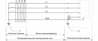
Three-phase networks are widely used in industry. This is a special case of multiphase systems. In essence, everything is the same as a single-phase system, only multiplied by 3, i.e. the use of three phases and three grounds simultaneously. First invented by N. Tesla, subsequently improved by M. O. Dolivo-Dobrovolsky. The improvement was that to transmit three-phase electric current it was possible to throw out extra wires; four were enough: three phases ABC and a neutral wire, or three phases altogether, abandoning zero. The neutral wire is very often grounded. In the figure below, zero is common.
Why 3 phases, and no more, no less? On the one hand, 3 phases are guaranteed to create a rotating magnetic field, which is so necessary for electric motors to rotate or received from power plant generators; on the other hand, it is economically beneficial from a material point of view. Less is not possible, but more is not necessary.
To ensure that a rotating field is created in a three-phase network, the voltage phases must be shifted relative to each other. If we take the full period of voltage to be 360 degrees, then 360/3 = 120 degrees. Those. the voltage of each phase is shifted relative to each other by 120 degrees. See picture below.
Here is a graph of the voltage of a 3-phase 380V network over time. As can be seen from the figure, everything is the same as with a single-phase network, only there are more voltages. 380V is the so-called linear network voltage Ul, i.e. voltage measured between two phases. The figure shows an example of finding the instantaneous value of Ul. It also varies according to a sinusoidal law. Also, along with linear voltage, phase Uph is distinguished. It is measured between phase and zero. The phase voltage in this three-phase network is 220V. By phase and line voltage, of course, we mean effective voltage. The linear to phase voltage is related as the root of three.
The load can be connected to a three-phase network in any way - to phase voltage: between any phase and zero, or to line voltage: between two phases. If the load is connected to phase voltage, then this connection diagram is called a star. It is shown above. If to line voltage, then the connection is delta. If the same load is connected to line voltages between all three phases, then such networks are symmetrical. No current flows through the neutral wire in symmetrical networks. See fig. below. Industrial networks are also considered conditionally symmetrical. As a rule, zero is present in such networks, but only for protective purposes. Sometimes it may be absent altogether. A funny picture from the wiki clearly illustrates how current flows in such networks.
This concludes our brief overview of electrical networks and electricity. Perhaps in the future I will explain in detail how a diode and transistor work, what a zener diode, thyristor and other elements are. Write what you are interested in reading about.
Bibliography
- The Art of Circuit Design, P. Horowitz. 2003.
- GROUNDS FOR GROUNDING. A Circuit-to-System Handbook, Elya B. Joffe, Kai-Sang Lock.
- Wiki and Internet resources.