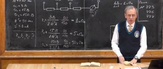
Spreading phenomenon
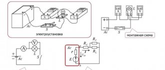
In a 3-phase supply network operating according to a circuit with a so-called “isolated” neutral, a phase-to-ground fault can be judged by the readings of an indicator device (voltmeter) connected to it. To organize such measurements, its control probes are connected to the contacts of the secondary winding of an NTMI type instrument transformer, capable of withstanding long-term overvoltages.
When a conductor is directly or directly short-circuited to ground, the winding of the instrument transformer is short-circuited, and the readings of the corresponding voltmeter will be zero.
At the same time, the total magnetic flux (induction) in the other two NTMI windings will increase by √3 times, and the corresponding voltmeters measure the linear voltage instead of the phase voltage.
In the case of practical measurement of capacitive ground fault current, the “selection” method is used. Its essence lies in deliberate displacement of the neutral (supplying alternating voltage to the neutral) and measuring the currents arising from this.
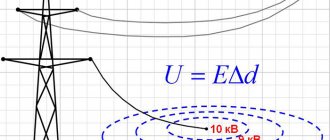
The method is applied only in dry weather to networks of no more than 10 kV. Those workers who have received permission can carry out measurements of ground fault current.
The calculated earth fault current is determined as the geometric sum of its capacitive components in all working conductors according to the following formula:
As the length of the network increases, its capacity naturally increases and, according to the formula, the emergency leakage current increases. At the same time, in accordance with the requirements of the PUE, the current value in the circuit should not exceed the following values:
To fulfill this requirement, compensation of capacitive ground fault current must be forcibly organized in 3-phase supply circuits.
Spreading zone (local ground) in the grounding section
Everyone has probably heard that the potential of the earth (the surface of the globe) is zero. And so what? Everything on the surface of the earth has zero potential. It is important to understand here that the earth is a large conducting object whose potential cannot be changed. Therefore, it acts as a kind of starting point. And it is naive to believe that if you touch a grounded electrical appliance, the body of which has been exposed to a dangerous potential, and at that time you stand on the ground, this will somehow help. Here everything is much more complicated and the fantasy of many about the magical neutralization of dangerous potential by the zero potential of the earth does not work. Therefore, it is important to understand grounding correctly.
Let's start the analysis with the spreading zone (local ground). And we will do this extremely clearly and in simple language. The first thing we need is a grounding electrode. Let's take a conventional house, in which household electrical appliances are grounded according to the TT system, that is, the ground electrode is not connected to the solidly grounded neutral of the transformer through a PEN conductor.
Now let’s imagine that for some reason a dangerous phase potential ended up on the housings of grounded devices and, naturally, on the ground electrode. And at this stage, many do not understand what happens next to this potential and where the current goes. Someone will simply say that it spreads through the ground electrode, and they will be right. And someone will come up with an idea and will think that since the current spreads in the ground, it means it disappears there. So the current does not disappear anywhere. By the way, by current I mean the ordered movement of charged particles. And if we are talking about alternating current, then by movement we should understand vibrations, since with a frequency of 50 Hertz and a low speed of electrons, the latter will dangle back and forth within a millimeter, and maybe even less.
But since the current does not disappear anywhere without a trace, let’s figure out where it goes and what does spreading have to do with it. When there is a short circuit to the frame, the current passes through the ground electrode to the ground. The current flows into the ground, and a spreading field is created around the ground electrode. The parameters of the spreading field depend on different conditions. These include the shape and size of the ground electrode, soil composition, soil moisture, time of year, and so on. All together, these conditions can be replaced by one parameter - resistance to current spreading.
Now is the time to understand the resistance to current flow. To do this, first of all you need to know the resistivity of a particular soil. Approximate values of average resistivities of individual types of soils p, Ohm m:
| Soil name | Average resistivity, Ohm m |
| Sand | 500 |
| Sandy loam | 300 |
| Loam | 80 |
| Clay | 60 |
| garden soil | 40 |
| Chernozem | 50 |
| Peat | 25 |
| Porous limestone | 180 |
| Sandstone | 1000 |
Let's take sandy loam with a resistivity of 300 Ohm m as an example. What does 300 Ohm m mean? Let's try to explain this in simple words. The earth is a conductor. Let's imagine a conductor made of sandy loam with a cross-section of 1 m². Each meter of such a conductor will create a resistance of 300 Ohms. But the earth is a huge conductor with resistance tending to zero.
How to compare 300 Ohm and 0 Ohm? Everything is very simple. The current flowing into the ground diverges in all directions from the point of contact with the ground. Concentric spheres are formed around the ground electrode, increasing with distance from the entry point. One can imagine that the electrode is surrounded by concentric layers of soil of equal thickness. The layer closest to the electrode has the smallest surface area but the greatest resistance. As you move away from the electrode, the surface of the layer increases and its resistance decreases. Ultimately, the contribution of the resistance of remote layers to the resistance of the soil surface becomes insignificant. That is, the current spreading in the soil reaches a zone where the soil resistance is almost equal to zero. And then the entire volume of soil can simply be conventionally represented as a conductor with zero resistance. The area beyond which the resistance of the earth layers can be neglected is called the spreading zone (local ground or area of effective resistance). Its size depends on the depth of immersion of the ground electrode into the ground.
In the spreading zone, a gradual drop in voltage occurs. In our example, we considered a soil resistivity of 300 Ohm m. Accordingly, the voltage drop is the sum of the voltage drops in each sphere, taking into account the contact area and soil resistivity. By increasing the contact area using a ground electrode, we reduce the resistance to current flow and reduce the voltage drop in the local ground zone. If we assume that the current flow resistance of the ground electrode is 4 ohms, then the voltage drop across this ground electrode is the same as the total voltage drop in each sphere of the effective resistance region. Moreover, the points of each sphere correspond to the same intensity and current density (not to be confused with current strength). Current density is a value equal to the ratio of the current to the cross-sectional area of the conductor S. Only in our case we considered the areas of spheres at different distances.
It is worth remembering that if, at the moment the current drains from the ground electrode, a person finds himself in the current spreading zone, then his legs will be at points with different potentials. The tension of the step will be applied to the person along the leg-to-leg path.
Consequences of a short circuit
Current spreading in networks with an insulated neutral is possible only through a wire in direct contact with the ground. The closest example of such a situation is an artificial ground electrode.
Current drain
An emergency phase-to-ground fault leads to the same effect, resulting in a sharp decrease in the potential of the conductor relative to the ground.
In this situation, such a wire formally turns into a single ground electrode.
The voltage at the point of contact is reduced to a value corresponding to the product of the current flowing through it and the value of the soil's resistance to its spreading.
This phenomenon is very useful in terms of reducing the danger of accidental damage to the line. At the same time, lowering the phase potential leads to a number of undesirable consequences.
One of the negative consequences is the effect of potential distribution over the earth's surface near the contact zone. As a result, potentials of different magnitudes appear at points at different distances from the grounding structure, creating voltage drops that are dangerous for people in this area.
This circumstance was the reason for the introduction of such an indicator as “step voltage”, determined by the potential difference between his feet when moving within the boundaries of the danger zone.
Due to the fact that the potential decreases exponentially with distance from the contact point, the maximum step voltage is observed close to it. The minimum of this value appears in areas sufficiently remote from the epicenter of the accident.
The nature of the distribution of ground fault current, the magnitude of the spreading resistance and the distribution of potentials in a dangerous area - all these indicators depend on the geometric parameters of the formed connection. They are also significantly influenced by the condition of the soil at the time of the accident (high humidity, dryness or other factors).
Arc occurrence
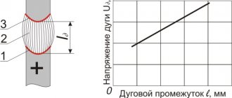
Another consequence of a phase conductor being shorted to ground is the formation of an electric arc, during the combustion of which a large amount of heat is released and air ionization is observed. This creates conditions conducive to the appearance of a short circuit in linear interphase circuits.
The intermittent nature of the arc formed during a ground fault leads to the appearance of significant overvoltages of up to 3.2 Uph. In order to reduce the amplitude of capacitive currents, increase the voltage recovery time in the emergency phase, as well as limit overvoltages during subsequent arc ignitions, a special arc suppression reactor.
Current spreading in the ground
A ground fault can occur due to contact between live parts and a grounded frame when the electrical insulation of the equipment is damaged, a broken wire falls to the ground, etc. In these cases, the current flows into the ground through an electrode that is in contact with the ground. A metal conductor (electrode) immersed in the ground is called a ground electrode.
The current, flowing from the ground electrode into the ground, is distributed over a significant volume of it. The space around the ground electrode, where the potentials are not equal to zero, is called the current spreading field. If a person is in the field of current spreading, then the current passes through his legs.
The voltage between two points of an electrical current circuit, located one step apart from each other, on which a person is simultaneously standing, is called step voltage or step voltage.
The law of potential distribution in the electric field of the ground electrode is described by a complex relationship determined by the size, shape of the ground electrode and the electrical properties of the soil.
To identify the law of distribution of ground potentials in the current spreading field, we make the following assumption: current I
W flows into the ground through a single hemispherical ground electrode of radius
r
0 immersed in homogeneous isotropic soil with electrical resistivity r (Fig. 1).
The spreading current lines are directed along radii from the ground electrode as from the center, and the sections of the earth as a conductor are hemispheres with radii r
<
r
1<
r
2<…<
r
n.
Rice. 1 Spreading of current in the ground from a hemispherical
ground electrode
The surfaces of these sections are respectively equal:
.
The current is distributed evenly over these surfaces, since the soil is homogeneous and isotropic. Current density d on the ground surface at point A located at a distance x
from the center of the ground electrode, is defined as the ratio of the ground fault current
I
З to the surface area of a hemisphere with radius
x:
(1)
To determine the potential of point A lying on a surface of radius X.
Let us select an elementary layer of thickness dx
(
see Fig. 1). Voltage drop in this layer:
dU=Edx,
(2)
where E
= dr – electric field strength.
The potential of point A or the voltage of this point relative to the ground is equal to the total voltage drop from point A to a point at infinity with zero potential:
(3)
Substituting into expression (3) the corresponding values from expressions (1) and (2), as well as the value of E.
we get
(4)
Having integrated expression (4) over x,
we obtain an expression for the potential of point A, or the voltage of this point relative to the ground, in the following form:
(5)
Since , then (5) takes the form:
From the resulting expression it is clear that as the distance from the ground electrode increases, the potential of the points decreases, and there is a hyperbolic dependence of the potential of the point on the distance (Fig. 2).
Rice. 2 Potential distribution curves of a hemispherical ground electrode
Ground electrode potential with radius r
0or grounding voltage relative to ground:
(6)
The ground electrode has the highest potential. Points lying on the ground surface have a lower potential the further they are from the ground electrode. At the limit, the potential of remote ground points tends to zero. The reason for this distribution of potentials lies in the peculiar shape of the conductor (earth), the cross-section of which increases in proportion to the second power of the radius of the hemisphere (Fig. 3).
The current flowing from the ground electrode spreads over the ground, which resists the flow of current. The resistance to current spreading of the ground electrode is defined as the total resistance of the soil from the ground electrode to the point with zero potential. For a hemispherical ground electrode located in a homogeneous isotropic soil, the spreading resistance R
RAS has the form:
(7)
The greatest resistance to current spreading is provided by the layers of earth (soil) lying near the ground electrode, since the current flows here through a small cross-section. The greatest voltage drops occur at these points.
Rice. 3 Simplified model of earth conductor
As you move away from the ground electrode, the cross-section of the conductor (earth) increases and the resistance to current flow decreases, and therefore the voltage drop decreases. At a distance of 10¸20 m from the ground electrode, the cross-section of the conductor (earth) becomes so large that the earth offers virtually no resistance to the passing current. Thus, the potential of ground points located at a distance of 10¸20 m from a single hemispherical ground electrode is practically zero.
Step voltage is defined as the potential difference between points, for example A and B (see Fig. 4).
. (8)
Since point A is removed from the ground electrode at a distance r
, then its potential, based on (5) with a hemispherical ground electrode, is obtained in the form:
Point B is located at a distance r+a from the ground electrode,
i.e. point B is distant from point A by the amount of person’s step
a.
Point B potential:
Rice. 4 The emergence of stepper
voltage
The step voltage is greatest near the ground electrode. As you move away from the ground electrode, the step voltage decreases. If a person’s feet are at the same distance from the ground electrode, i.e. on a line of equal potential (equipotential), then the step voltage is zero. Let the distance from the ground electrode to the equipotential at which a person is located be equal to r
, then the step voltage is zero.
The value of the step voltage depends on the step size. Reducing it leads to a decrease in step voltage. The step voltage depends on the grounding voltage:
(10)
where is the step voltage coefficient, taking into account the shape of the potential curve.
The step voltage coefficient bШ depends on the shape and configuration of the ground electrode and the position relative to the ground electrode of the point at which it is determined. The closer to the ground electrode, the greater bSh and, therefore, the greater the step voltage. A person located outside the current spreading field (at a distance of 10–20 m from the ground electrode) is not affected by the step voltage, since bSh = 0. As can be seen from the expression for determining the step coefficient, its value is less than unity. Thus, the step voltage is part of the ground electrode voltage. The resulting expression for determining bSh is valid only for a hemispherical ground electrode.
For other forms of ground electrodes, as well as for earth electrodes consisting of several electrodes electrically connected to each other, the potential distribution is determined by complex dependencies. Consequently, the step voltage coefficient in various cases is determined by very complex expressions. For a single extended grounding switch of length l
>20 m bW=0.14, and for a grounding conductor consisting of a number of rods connected by a strip, bW=0.10.
Finding a person in the field of current spreading can lead to injury if the step voltage U
of U
according to electrical safety conditions .
The area around the ground electrode, in which U
Ш>
U
DOP, is called a dangerous
. The radius of the danger zone depends on the voltage on the ground electrode and the resistivity of the soil.
Rice. 5 Potential distribution curves
group grounding electrode
Let the ground electrode consist of two hemispherical electrodes. The potential distribution picture for such a ground electrode is shown in Fig. 5. The spreading fields of the ground electrodes overlap each other, and any point on the soil surface between the electrodes has a significant potential. As a result, the step voltage decreases.
To reduce step voltages, grounding electrodes are placed along the contour at a short distance from each other, which leads to potential equalization due to the superposition of spreading fields. Sometimes, when performing loop grounding, horizontal strips are laid inside the loop, which additionally equalize the potentials inside the loop (Fig. 6).
Rice. 6 Ground electrode with potential equalization:
plan view (top); potential curve shape (bottom)
Loop grounding ensures the safety of work in the grounding zone, since the step voltage U
W <
U
DOP, i.e. there is no danger zone. To reduce step voltages outside the circuit, special metal buses are laid in the ground, connected to a ground electrode (see Fig. 7). In this case, the potential decline occurs along a flat curve, and the step voltages decrease.
Compensatory protection measures
In accordance with the provisions of the PUE, under normal network operating conditions, special measures must be taken to protect against possible ground faults.
To limit capacitive currents, a special arc suppression reactor is introduced into the transformer neutral (see Figure 1, b). With its help, it is possible to reduce (compensate) the current of a single-phase ground fault that occurs immediately after an accident.
It has been practically established that in the presence of a compensator, overhead and cable lines can operate in critical emergency mode for quite a long time and here’s why.
As soon as the inductive current Ip flowing in the reactor is compared in magnitude with the out-of-phase capacitive component Ic, a compensation effect is observed, in which Iр + Iс = 0 (the phenomenon of current resonance).
Reactors with inductive impedance are quite simply configured to operate with a variable value of the compensation flow and can be operated in under- and overcompensation modes.
The use of an arc suppression reactor has a certain effect on the distribution of potentials in linear wires and in the neutral. In the latter, a bias voltage Ucm appears, caused by asymmetry in the circuit and applied to the reactor terminals.
In the resonant mode, such a mismatch leads to a distortion of the normal pattern of potential distribution even in the absence of a single-phase fault (SFC).
Artificial prevention of resonance phenomena can be achieved by deliberately mismatching the corresponding circuits, as a result of which it is possible to reduce Ucm and equalize the readings of control devices.
Additional note. It is allowed to vary the value of compensation currents within limits in which the mismatch formed in the event of an accident would not lead to the appearance of Ucm more than 0.7 Uph.