The essence of the phenomenon
Voltage is the electrical driving force that is designed to push free types of electrons from one atom to another in a certain direction. A mandatory requirement for the flow of charges is the presence of a circuit with a closed loop, which creates the conditions for them to move. If there is a break in the electrical circuit, then the process of directional movement of particles stops.
Note! It is worth noting that the unit of voltage in an electrical circuit depends on the material of the conductor, how the load is connected, and what the temperature is.
Varieties
There are two types: constant and variable. The first is in electrostatic types of circuits and those that have direct current. Variable occurs where there is sinusoidal energy. It is important that sinusoidal energy is divided into effective, instantaneous and average rectified. The unit of measurement for electric current voltage is volt.
It is also worth noting that the amount of energy between the phases is called the linear phase, and the indicator of the ground and phase current is called the phase current. A similar rule is used in all overhead lines. On the territory of the Russian Federation, the standard household electrical network is 380 volts, and the phase network is 220 volts.
Constant pressure
Constant is the difference between electrical potentials, at which the same value remains the same with polarity changes over a specific period. The main advantage of constant energy is the fact that there is no reactive power. This means that all the power that is generated by the generator is consumed by the load, excluding wire losses. Flows throughout the entire conductor cross-section.
As for the disadvantages, there is the difficulty of increasing with decreasing energy, that is, at the moment of converting it due to the design of the converters and the lack of powerful semiconductor switches. In addition, it is difficult to decouple high and low energy.
Note! Constant energy is used in electronic circuits, galvanic cells, batteries, electrolysis plants, welding tools, inverter converters and many other devices.
AC voltage
An alternating current is a current that changes in magnitude and direction periodically, but at the same time maintains its direction in an electrical circuit unchanged. It is often called sinusoidal. One direction in which energy moves is called positive, and the other is called negative. Therefore, the resulting quantity is called positive and negative. This exponent is an algebraic quantity. In answer to the question of what the unit of voltage is called, it should be noted that it is a volt. Its value is determined by direction. The maximum value is amplitude. It happens:
- three-phase;
- multiphase.
It is actively used in industry, at a power station, at a transformer substation and is transmitted to every home using electrical transmission lines. Mostly three phases are used for connection. This type of electrification is common on many railways.
Note! It is worth noting that there are also some types of dual-system electric locomotives, which operate in many cases at a variable rate.
Safety regulations
Worth paying attention:
- Grounding is required.
- The device and chain cannot be touched with bare hands.
- If unforeseen situations occur, stop work immediately and make sure that the measurement does not have consequences. For example, a fire will not be created.
- The device is connected in parallel to an already assembled circuit.
- The workplace must be isolated from strangers.
- The person measuring must have an understanding of safety precautions, know the design of the device and the principle of its operation.
- The chain must be assembled correctly.
- At the end of the work, the device is turned off and disassembled, placed in the storage location in appropriate cases. The worker removes protective equipment and thoroughly cleans his hands.
The answer to the question, what is the name of the device for measuring electrical voltage, is very simple, as is the procedure itself. The main thing is to act carefully and treat the equipment with care. In this case, the equipment will last for centuries.
Electrical measuring instruments
- a class of devices used to measure various electrical quantities. The group of electrical measuring instruments also includes, in addition to the measuring instruments themselves, other measuring instruments - gauges, converters, complex installations.
AC ammeter
AC voltmeter
Voltage measurement. Types and principle of measurements. Peculiarities
In practice, voltage measurements have to be performed quite often. Voltage is measured in radio engineering, electrical devices and circuits, etc. The type of alternating current can be pulsed or sinusoidal. Voltage sources are chemical elements or current generators.
Types of voltage measurements
Pulse current voltage has amplitude and average voltage parameters. Sources of such voltage can be pulse generators. Voltage is measured in volts and is designated “V” or “V”. If the voltage is alternating, then the symbol “
", for constant voltage the symbol "-" is indicated. The alternating voltage in the home household network is marked
On batteries and galvanic cells, when indicating voltage, the “-” sign is not used, but only numbers are put, for example, “1.5 V”. On the body of the galvanic cell there must be a “+” symbol near the positive pole. In practical electrical measurements, multiple units are used: millivolts, kilovolts, etc.
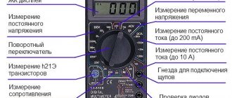
AC voltage has a polarity that changes over time. In a household network, the voltage changes polarity 50 times per second, which means a frequency of 50 hertz. Constant voltage has constant polarity. Therefore, to measure AC and DC voltages, measuring instruments that differ in design are used - voltmeters. They can be digital or analog (arrow). However, there are universal instruments that are capable of measuring direct and alternating voltage without switching modes.
To begin measurements, the measuring device is connected in parallel to the terminals of the power source or load with special probes.
In addition to voltmeters, electronic oscilloscopes are used to measure voltage.
These are instruments designed to measure and control the characteristics of electrical signals. Oscilloscopes work on the principle of deflecting an electron beam, which produces an image of the values of variable quantities on the display.
AC voltage measurement
According to regulatory documents, the voltage in a household network must be equal to 220 volts with a deviation accuracy of 10%, that is, the voltage can vary in the range of 198-242 volts. If the lighting in your home has become dimmer, lamps have begun to fail frequently, or household devices have become unstable, then to identify and eliminate these problems, you first need to measure the voltage in the network.
Before measurement, you should prepare the existing measuring device for use:
- Check the integrity of the insulation of control wires with probes and tips.
- Set the switch to AC voltage, with an upper limit of 250 volts or higher.
- Insert the tips of the control wires into the sockets of a measuring instrument, for example, a multimeter. To avoid mistakes, it is better to look at the designations of the sockets on the case.
- Turn on the device.
The measurement limit of 700 volts is selected on the multimeter. Some devices require that several different switches be set to the desired position in order to measure voltage: the type of current, the type of measurement, and also insert the wire tips into certain sockets. The end of the black tip in the multimeter is inserted into the COM socket (common socket), the red tip is inserted into the socket marked “V”. This socket is common for measuring any kind of voltage. The socket marked “ma” is used for measuring small currents. The socket marked “10 A” is used to measure a significant amount of current, which can reach 10 amperes.
If you measure the voltage with the wire inserted into the “10 A” socket, the device will fail or the fuse will blow. Therefore, you should be careful when performing measuring work. Most often, errors occur in cases where the resistance was first measured, and then, forgetting to switch to another mode, they begin to measure the voltage. In this case, a resistor responsible for measuring resistance burns out inside the device.
Learn more about current measurement
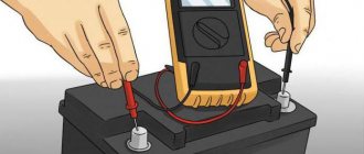
In principle, everyone who studied physics at school knows how to measure the current strength in a section of a circuit. It is necessary to pass current through the device: that is, connect it to the open circuit. In laboratory conditions it is simple, there are verified parameters and a device with a safety margin. How, for example, can you check for current leakage on a car battery?
Not every tester is suitable for this type of work. The current measurement limit must, at a minimum, exceed the power of the headlight lamps. For example, you have 55 W halogen headlights. The total power is 110 W, divided by the voltage 12 volts, we get a value of about 10 amperes. This means that the household tester must have a DC measurement mode with a limit of 20 amperes.
Next is the standard inclusion (as in a school laboratory):
- Disconnect the negative wire (ground) from the battery.
- We securely connect the negative measuring cable of the tester to the negative terminal of the battery.
- We connect the positive measuring cable of the device to the negative wire of the car.
We see leakage current when consumers are disconnected. If it is measured in amperes, we remove the fuses one by one and find the node that gives the parasitic load.
There should not be zero current: the on-board computer, radio, and alarm system (if equipped) are constantly powered. But these are tens of milliamps. If the value is an order of magnitude higher, the tester will help you find the problem area.
How does tension arise?
All substances consist of atoms, which are a positively charged nucleus around which smaller negative electrons circle at high speed. In general, atoms are neutral because the number of electrons matches the number of protons in the nucleus.
However, if a certain number of electrons are taken away from the atoms, they will tend to attract the same number, forming a positive field around themselves. If you add electrons, then an excess of them will appear, and a negative field will appear. Potentials are formed - positive and negative.
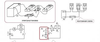
Capacitance measurement
Determining the capacitance of a capacitor or other capacitive devices can also be carried out in various ways. The simplest of them is the ammeter-voltmeter method (Fig. 6, a).
Rice. 6. Capacitance measurement circuits
It is in many ways similar to the same method of measuring resistance, with the only difference being that the circuit is powered by an alternating sinusoidal voltage from a low or high frequency generator (or from the network). The capacitance of a capacitor is determined by the following formula:
where f is the frequency of the alternating voltage.
Capacitance is found according to Ohm's law according to instrument readings
It is more convenient to measure small capacitances using the resonance method (Fig. 6, b). The measured capacitor Cx is connected to a known inductance L, forming an oscillating circuit. The circuit is supplied with sinusoidal voltage from the generator. Using an electronic voltmeter, the voltage on the circuit is measured. At resonance it reaches its maximum.
It is known that the resonant frequency of the circuit can be expressed by the following formula:
Consequently, with a known value of inductance in the circuit and a resonance frequency determined from the maximum readings of a voltmeter, the desired value of capacitance Cx can be found.
The easiest way to measure large capacitances (for example, electrolytic capacitors) is to discharge the capacitor to a known resistance R. It is known that in a time equal to the time constant of the capacitor discharge circuit, its voltage decreases by e times, where e = 2.71 ... is the base of the natural logarithm The time constant of the capacitor discharge circuit to the resistor is determined by the relation
The circuit for measuring capacitance using this method (Fig. 6, c) consists of a constant supply voltage source, known by the value of the resistor R, an electronic voltmeter PV, a switch S and terminals for connecting a capacitor. Using the switch S, the capacitor Cx is charged to the voltage of the power source, and after switching the capacitor to discharge, the time t is measured using a stopwatch, after which the capacitor is discharged to the voltage Upit/e. The capacitance of the capacitor is determined by the formula
Capacitances of capacitors can also be measured using AC bridges.