Voltage transformer working principle
For direct connection to high voltage, very bulky devices and relays would be required due to the need to make them with high-voltage insulation. The manufacture and use of such equipment is practically impossible, especially at voltages of 35 kV and above.
The use of voltage transformers allows the use of standard measuring instruments for high voltage measurements, expanding their measurement limits; relay windings connected via voltage transformers can also have standard designs.
In addition, the voltage transformer isolates (separates) the meters and relays from high voltage, making them safe to operate in the substation.
The main fundamental difference between measuring voltage transformers (VT) and current transformers (CT) is that they, like all power models, are designed for normal operation without a short-circuited secondary winding.
At the same time, if power transformers are designed to transmit transported power with minimal losses, then voltage instrument transformers are designed for the purpose of highly accurate repetition on the scale of primary voltage vectors.
voltage transformer
Principles of operation of a voltage transformer
The design of a voltage transformer, like a current transformer, can be represented by a magnetic core with two windings wound around it:
- primary;
- secondary.
Special grades of steel for the magnetic core, as well as the metal of their windings and the insulation layer are selected for the most accurate voltage conversion with the least loss. The number of turns of the primary and secondary coils is calculated in such a way that the nominal value of the high-voltage line voltage of the network supplied to the primary winding is always reproduced by the secondary value of 100 volts with the same vector direction for systems assembled with a grounded neutral.
If the primary energy transfer circuit is created with an isolated neutral, then 100/√3 volts will be present at the output of the measuring winding.
To create different ways of simulating primary voltages, not one, but several secondary windings can be located on the magnetic core.
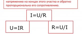
Transformation ratio
Transformers can be step-up and step-down, to determine this you need to find out the transformation ratio , with its help you can find out which transformer. If the coefficient is less than 1, then the transformer is step-up (this can also be determined by the values; if there is more in the secondary winding than in the primary, then it is step-up), and vice versa, if K>1, then it is step-down (if there are fewer turns in the primary winding than in the secondary).
Formula for calculating the transformation ratio
- U1 and U2 - voltage in the primary and secondary windings,
- N1 and N2 - number of turns in the primary and secondary windings,
- I1 and I2 - current in the primary and secondary windings.
Learn more about calculating the transformation ratio.
Decoding and markings
To distinguish between types of models, letter markings are used:
N – voltage transformer; T – three-phase model; O – single-phase TN; C – dry (air cooling); M – oil; A – anti-resonance models; K – cascade devices; F – porcelain body type; I – five-rod transformer containing a winding for insulation control; L – designs in a cast body; DE – capacitive; G – grounded (the primary coil must be grounded).
Technical specifications
Technical parameters of transformers:
voltage value at the primary phase input; voltage at the terminals of the secondary phase windings; power factors; maximum short circuit voltages. Important information includes the parameters of the rated frequency and the accuracy class for the rated transformation ratio. On some models, manufacturers indicate angular errors and permissible voltage errors.
Basic information is indicated on the voltage transformer nameplate.
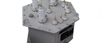
Single-phase voltage transformer device
single-phase voltage transformer device
Single-phase voltage transformer device:
- a - general view of the voltage transformer;
- b - removable part;
- 1.5 - bushings;
- 2 — bolt for grounding;
- 3 - drain plug;
- 4 - tank;
- 6 - winding;
- 7 - core;
- 8 — screw plug;
- 9 - high-voltage input contact
Single-phase voltage transformers are most widespread. They are produced for operating voltages from 380 V to 500 kV.
The design dimensions and weight of a voltage transformer are determined not by power, as with power transformers, but mainly by the volume of insulation of the primary winding and the dimensions of its high voltage terminals.
Voltage transformers with rated voltages from 380 V to 6 kV are designed with dry insulation (the windings are made of PEL wire and impregnated with asphalt varnish).
The Sverdlovsk Current Transformer Plant produces voltage transformers for 6, 10, 35 kV with cast insulation.
Transformers with voltages of 10 - 500 kV have oil insulation (the magnetic circuit is immersed in transformer oil).
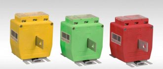
An example of the purpose and scope of application of voltage transformers ZNOL-NTZ
Transformers are designed for outdoor installation in open switchgears (OSD). Transformers provide signal transmission of measuring information to measuring instruments, protection and control devices, and are intended for use in commercial electricity metering circuits in AC electrical installations for a voltage class of 35 kV. Transformers are made in the form of a supporting structure.
The transformer housing is made of a compound based on the hydrophobic cycloaliphatic resin “Huntsman”, which at the same time serves as the main insulation and protects the windings from mechanical and climatic influences. The operating position of the transformers in space is vertical, with high-voltage leads up.
circuit diagram for switching on the windings of the ZNOL-NTZ voltage transformer
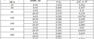
- See ZNOL transformers, characteristics diagrams in the table
Inner and outer contour
Typically, the main bus inside a building is installed inside the input device. It can only be made from steel or copper. The use of aluminum in this case is not permitted. Measures are taken to prevent unauthorized people from freely accessing it. The tire is placed in a locked cabinet or in a separate room.
Connect to it:
- metal elements of the building structure;
- external ground loop conductor;
- conductors PE and PEN types;
- metal pipelines and conductive parts of water supply, air conditioning and ventilation systems.
The external contour of the house is created taking into account the above-mentioned PUE standards for individual parts of the system. This will allow you to obtain the required minimum resistance of the grounding system (Ohm), which is sufficient for reliable protection. For re-grounding, it is recommended to use natural-type grounding electrodes.
The resistance (Ohm) of the re-grounding switch is not clearly defined by the provisions of the PUE.
Below are some important features of a standard private house ground electrode:
- The main part, the vertical elements, are installed at a short distance from the house, taking into account the soil parameters.
- A trench up to 0.8 m deep and at least 0.4 m wide is laid to them, in which horizontal sections of the chain are installed. There is no exact standard, but the dimensions of the trench must be sufficient for the smooth installation of elements.
- Vertical grounding rods up to 3 m long are installed in the corners of an equilateral (3 m each) triangle. These dimensions are provided as an example. There are no exact standards for length. There are standards only for the maximum permissible resistance of the protective system.
- To make it easier to drive them into the ground, the ends are sharpened.
- The strips are welded to the protruding parts.
- The trenches are filled with soil that is uniform in structure and does not contain crushed stone.
Installation of an external ground loop for a private house
If bolted connections are used in the grounding circuit, measures should be taken to prevent them from loosening. As a rule, the corresponding components are welded.
Voltage transformer connection diagrams
Instrument transformers are used to measure linear and/or phase primary quantities. To do this, the power windings are connected between:
- line wires to control line voltages;
- bus or wire and ground to read the phase value.
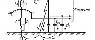
An important safety element for voltage instrument transformers is the grounding of their housing and secondary winding.
Increased attention is paid to the grounding of voltage transformers, because if the insulation of the primary winding breaks down on the housing or in the secondary circuits, a high-voltage potential will appear in them, which can injure people and burn equipment.
Intentional grounding of the housing and one secondary winding diverts this dangerous potential to the ground, thereby preventing further development of the accident.
The simplest connection diagram is used at service points for lines under voltage of 6 - 10 kV. Transformers connected in this way are used to turn on the voltmeter and supply voltage to the relay of the ATS device.
An example of such a circuit is shown in Fig. 7.
Rice. 7. Simple voltage transformer connection diagram
Figure 8 shows a circuit used to switch on single-phase transformers to supply safe voltage to loads powered from the secondary windings. This circuit uses a group of single-phase transformers, the coils of which are connected according to the star principle. Please note that the primary windings are connected to a solidly grounded neutral.
Rice. 8. Another example of a connection diagram
This scheme is used in 0.5 – 10 kV networks for connecting measuring instruments and meters. Voltmeters used to monitor insulation are connected using a similar circuit.
The circuit is effective for receiving signals indicating single-phase ground faults. There are other connection schemes, in particular according to the open delta connection type. The peculiarity of such schemes is that the power of a group of two VTs is less than the power of three devices connected in a full triangle circuit not by 1.5 times, but by √3 times.
Some circuits use a combined connection of windings. A delta-star connection is suitable for this purpose. In the operation of such circuits, the rated voltage is 173 V. The specified connection method is used in systems for regulating the excitation of generator and compensator windings.
Grounding of 36 Volt lighting transformers
Features of the application and design of welding transformers
To increase the safety of people, the rules for constructing electrical installations require grounding not only the transformer body, but also its secondary winding. Then, in the event of a breakdown of the primary winding, where 220 or 380 Volts flow, this deadly voltage will not appear in the lighting circuits.
In any case, human life is a priority in any work, so before touching the metal body of any electrical apparatus, device, cabinet, panel, etc., you should visually verify the existence of grounding and its integrity.
XXI CENTURY Candy Fudge Scented water
266 ₽ More details
Video baby monitor Motorola MBP36S (white)
12900 ₽ More details
Leather women's shoes
Voltage transformer for voltages up to 35 kV
A voltage transformer for voltages up to 35 kV is no different in principle from a power step-down transformer. It consists of a magnetic circuit made of electrical steel sheet plates, a primary winding and one or two secondary windings. In Fig. 2.1. shows a diagram of a voltage transformer with one secondary winding. A high voltage Ub is applied to the primary winding and the voltage of the secondary winding U2 is connected to the measuring device.
rice. 2.1 Connection diagram for a single-phase voltage transformer
Transformers are used in outdoor (type NOM-35, ZNOM and NKF series) or indoor AC installations with a voltage of 0.38-500 kV and a nominal frequency of 50 Hz. Three-winding transformers NTMI are designed for networks with an isolated neutral, NKF series (except NKF-110-5 - with a grounded neutral.
Single-phase, three-phase (five-leg) and cascade voltage transformers (VTs) are used in electrical installations. The choice of one or another type of voltage transformer depends on the network voltage, the value and nature of the load of the secondary circuits and the purpose of the voltage transformer (for modification purposes, for monitoring single-phase ground faults, for powering relay protection and automation devices).
Due to the relatively high cost of voltage transformers for 110-750 kV networks, in a number of cases, where this is possible under the operating conditions of measurement, protection and automation systems of electrical installations, they are replaced with capacitive voltage dividers.
Based on insulation, voltage transformers are divided into dry and oil insulated.
Designation of the voltage transformer in the diagram
Designation of a voltage transformer in the diagram
Transformer fuses protect voltage transformers from damage in the event of their operation in abnormal mode - in the event of a single-phase ground fault, in the event of ferroresonance phenomena occurring in the network, or in the event of a short circuit in the primary winding of the voltage transformer.
What are its advantages and disadvantages
Any electrical device has a number of advantages and disadvantages. Single-phase electrical transformers are no exception to this. They have more advantages than disadvantages. The main ones are:
- have one of the highest coefficients of performance (efficiency), which is 98%;
- They cool well and have increased resistance to overloads and short-term power surges;
- environmental safety of dry type. There is no oil in them, which means that nothing can harm the environment even after disposal;
- no need to comply with special fire safety measures at transformer installation sites;
- relatively small sizes, allowing the devices to be installed in small compartments.
You might be interested in this PSU from an electronic transformer
These devices are not without a number of disadvantages, which depend on their type and place of use:
- difficult maintenance if the device is oil-based. It should be regularly checked for breakdown and leakage of rubber gaskets, the replacement of which is quite difficult;
- dry single-phase devices do not tolerate high humidity, wind, chemical and physical influences, as well as pollution;
- high cost of dry transformers compared to oil transformers.
Conventional device for single-phase networks
Three-phase transformer
Among the electromagnetic devices of this type, the three-phase transformer stands out. It has magnetic and galvanic phase connections. The presence of a circuit of the first type is due to the connection of magnetic circuits into one system. In this case, the magnetic fluxes are located relative to each other at an angle of 120 °. A rod is not needed in this system, since when the centers of the three phases are combined, the sum of the electromagnetic channels is equal to zero, regardless of time. Thanks to this, a circuit with six rods is converted into a three-rod one.
Three types of circuits can be used to connect the windings of the device:
- A star connection can be made with or without output from common points. Here each winding is connected to a neutral point.
- According to a triangular diagram, the phases are connected in series.
- Zigzag is a pattern that is most often used during retraction from a common point. It connects three windings located on different magnetic cores.
The use of a three-phase transformer is more economical than the use of connected single-phase structures.
Voltage transformer load
The secondary load of the voltage transformer is the power of the external secondary circuit. The rated secondary load is understood as the highest load at which the error does not exceed the permissible limits established for transformers of a given accuracy class.
Voltage transformer designs
In installations with voltages up to 18 kV, three-phase and single-phase transformers are used; at higher voltages, only single-phase transformers are used.
At voltages up to 20 kV there are a large number of types of voltage transformers: dry (NOS), oil (NOM, ZNOM, NTMI , NTMK), with cast insulation ( ZNOL ). It is necessary to distinguish single-phase two-winding transformers NOM from single-phase three-winding transformers ZNOM. Transformers of types ZNOM-15, -20 -24 and ZNOL-06 are installed in complete conductors of powerful generators. In installations with voltages of 110 kV and higher, cascade-type voltage transformers NKF and capacitive voltage dividers NDE are used.
Voltage transformers
Instrument voltage transformers are designed to reduce primary voltages to values that are most convenient for connecting measuring instruments, protection relays, and automation devices. The use of instrument transformers ensures the safety of workers, since the high and low voltage circuits are separated, and also makes it possible to unify the design of devices and relays.
What is the difference between a current transformer and a voltage transformer?
By definition, these devices are designed to work with different electrical quantities as basic ones and, accordingly, the switching circuits will be different. For example, a current transformer is powered by a current source and does not work, and may even fail, if its windings are not loaded and no electric current flows through them. The voltage transformer is powered by voltage sources and, conversely, cannot operate for a long time in modes with high current loads
Video: Voltage Transformers
Technical characteristics of voltage transformers, connection diagrams. Factors influencing the accuracy class. Types of voltage transformers, identification of markings.
What is a voltage transformer
Peculiarities
As a rule, single-phase transformers are used in electrical networks and as power sources for various devices.
Based on the fact that the heating of a wire is directly proportional to the square of the current flowing through the wire, when transmitting energy over long distances it will be more profitable to use high voltages and low currents. To avoid damage to electrical appliances and reduce the amount of insulation at home, it is better to use low powers.
Also read: Why do you need a high-frequency suppressor?
In view of this, to reduce the cost of transporting electrical energy in the general power grid, power transformers are used in large quantities: first, they increase the voltage of generators at power plants before transmitting energy via cable, and after transportation, they reduce the voltage of power lines to the required level for widespread use.
Single-phase transformers
for “What is a voltage transformer”
- Rom
:V
My car, which was imported from Canada, has a 110 V engine heater installed. The heater power is unknown. The wire cross-section is about 0.75 in appearance. I want to buy or make a transformer. If you buy, then their powers are indicated in kVA, what does this mean, please explain, popularly. Or tell me how to do it. What power do you think can be selected?
Answer
- Expert
:
V
Measure the resistance of the heater (with any Ketai multimeter). Its power will be P = U*U/R, P in watts, U in volts, R in ohms. It is better to choose a transformer with approximately one and a half margin, just in case. In addition, the actual power will be less, because When heated, the resistance will increase and the power will decrease. How difficult it is to say, depending on what the heater is made of and how hot it gets. But this can also be written off as a reserve. In the case of a purely resistive load, such as a heater, we can assume that kVA = kW.
Answer
- Rom
:
V
Thanks Expert for the clarification! The resistance was measured earlier - 35 Ohms. P=U*U/R=110*110/35=346 W*1.5 = 519 W. Those. I can take a 0.5 kVA transformer
In what case is kVA not equal to kW?
Answer
- Expert
:
V
In theory, a simple 220/110 transformer is enough. It will be cheaper and safer with it, it provides complete isolation from the network, but an autotransformer does not.
In general, kVA = kW*KM, where KM is the power factor, it ranges from 0 to 1.
For a purely active load (heater, incandescent lamp, etc.), when there is just some kind of linear resistance, KM is close to 1.
But if the load has reactance (inductance, capacitance) or nonlinearity, or even all together, then the KM can be much lower, and then the difference between kVA and kW must be taken into account. kVA is the apparent power, kW is the active power consumed.
Answer
- Admin
:
V
Through an autotransformer, your heater will be galvanically connected to the network; it does not provide isolation. And through the transformer there is complete isolation. If you are absolutely sure that the heater insulation is designed for direct connection to the network and it is in order, you can use an autotransformer. If there is no such confidence, then it is better not to take risks.
Answer
- Volodya K
:
V
In general, kVA = kW*KM, where KM is the power factor, it can range from 0 to 1. For a purely active load (heater, incandescent lamp, etc.), when there is just some kind of linear resistance, KM is close to 1.
But if the load has reactance (inductance, capacitance) or nonlinearity, or even all together, then the KM can be much lower, and then the difference between kVA and kW must be taken into account. kVA is the apparent power, kW is the active power consumed.
Answer
- Elka
:
V
There is not enough brains or knowledge (or both) to understand why some current transformers and voltage transformers, seemingly of the same design, behave completely differently in operation.
Answer
- Denos Fox
:
V
The voltage transformer is powered by voltage. T E the primary winding will have a number of turns and a cross-section in accordance with the voltage. The current transformer is powered by the current generated in the conductor. That is, the primary winding will receive voltage from the current in the conductor. And this current will create a voltage in the primary winding.
Answer
- Elka
:
V
Denos Fox, thanks, but I still don't get it.
The purpose of the current transformer is clear to me - in order to measure a large current, it is necessary to first reduce the current strength to values acceptable for measurement by instruments, so as not to burn these instruments. But how it works is unclear. After all, if the voltage of the secondary winding of a CT reaches several thousand volts, when this winding is short-circuited, a gigantic current should flow through it, which, firstly, should burn the secondary winding with the measuring instruments connected to it, and secondly, lead to a sharp increase current of the primary winding with consumers connected to it.
They tried to explain to me that the current transformer is a step-up trans, so we get less current on the secondary winding, despite the higher voltage. But I still didn't understand the point.
Let's consider two cases:
Design differences between current and voltage transformers
In the first case, we connected the load to the step-down trance winding at a voltage of 220V, in the second, we connected the same load to the step-up trance winding at a voltage of 110,000V. But this does not mean that in the second case less current will flow through the load! Reducing the current with increasing voltage, in theory, only works if the power of the end consumer is constant, as in the very first example from the first post, when we transferred the current through a chain of trans to a consumer connected to a constant (in magnitude) voltage - 220V .
In the second example, we connect the load to different voltages, and the higher this voltage, the greater the current through the load will be, while the current in the lower voltage winding will still be greater than the current in the higher voltage winding. So why, in the case of a current transformer, does increasing the voltage on the secondary winding, to which the measuring instruments are connected, lead to a decrease in the current in it?
Answer
- Vovan
:
V
In a current transformer, the primary winding current does not depend on the secondary current.
Answer
- Petrovich
:
V
Will a 110V transformer withstand 220V? Those. at the output will we get double the voltage or will the primary winding just burn out?
Answer
- Vector
:
V
and if you apply 220 to the primary through a diode (it seems like just half will remain)
Answer
- Lech
:
V
Try turning on the Ilyich light bulb at 220 and see the result. Those who like assholes get it, they bring it, and then... Damn it, it's extreme.
Answer
- Sava
:
V
I just tried to connect 220 V to the primary trans (220 V) through a diode, like 1 half-wave (the LN through the diode burns at full intensity, that’s for sure) and the transformer, whether with or without a diode, produces the same number of volts. The output sine wave is approximately the same, not cut (tried with and without load)
Answer
- Gray P
:
V
But what are the real differences between the windings of transformers for different voltages - do they change the thickness of the varnish coating? If you measure the insulation resistance with a megohmmeter, this can show how much the transformer is designed for? For example, if you find a transformer without labels, how can you find out how much it is designed for?
Answer
Work technology
We select the location of the grounding conductors. Of course, not far from the house (facility), so that you do not have to lay a long conductor, which will have to be mechanically protected. It is advisable that the entire contour area be located on the territory that you control (you are the owner). So that one fine moment, your protective “ground” will not be dug up by a drunken excavator operator. So we won’t hammer in the pins behind the fence.
A vegetable garden (with the exception of a potato bed), a front garden, or a flower bed near the house will do. Cultivated areas are preferable and are regularly watered. And additional moisture in the ground will benefit grounding. If your soil has low resistivity, you can install grounding on the site, which will then be covered with asphalt or tiles. Under artificial turf, the ground does not dry out. And the risk of damaging the ground loop is minimal.
Depending on the shape of the site, we choose the order of arrangement of the electrodes: in a line or in a triangle.
If a triangle is selected, we mark out a site of the appropriate shape with sides of 2.5–3 meters. We dig a trench in the shape of an equilateral triangle to a depth of 70–100 cm, a width of 50–70 cm. We know that all ground electrodes are connected to each other. The conductor must be deepened to a distance of at least 50 cm, taking into account the minimum ground level (for example, digging a bed). If a coating is laid on top, its thickness is not taken into account. Only clean soil.
You can select all the soil, not just around the perimeter of the trench. The result will be a triangular pit 0.7–1.0 m deep. The finished circuit can be filled with soil with low resistivity. For example, ash or ashes. The salts will penetrate into the ground and will help reduce the overall resistance to current flow.
After which, in the corners of the pit (trench) we begin to hammer in the electrodes.
Parameters of grounding conductors (considering a vertical arrangement)
Steel without galvanic coating:
Circle - diameter 16 mm.
Pipe - diameter 32 mm.
Rectangle or corner - cross-sectional area 100 mm².
Galvanized steel
Circle - diameter 12 mm.
Pipe - diameter 25 mm.
Rectangle or corner - cross-sectional area 75 mm².
Circle - diameter 12 mm.
Pipe - diameter 20 mm.
Rectangle or corner - cross-sectional area 50 mm².
The soil should tightly adhere to the metal surface of the ground electrode. It is prohibited to paint electrodes!
But what if, according to calculations, the length of each of the three electrodes exceeds 1.5–2 meters? There are little secrets.
We connect the electrodes with a conductor. If the reinforcement is steel, welding is best. The copper rods are connected with a bolt tie; the conductor must have a cross-section of at least 30% of the cross-section of the electrodes.
After assembling the circuit, we measure the current flow resistance. The grounding loop requirements for individual housing are 10 ohms. It is better to entrust the measurement to certified specialists who have the appropriate equipment. Moreover, when receiving specifications from power engineers, you will still have to provide a grounding system for measurements. If the resistance is higher than normal, we add electrodes and weld them to the circuit. Until we get the norm.
Why ground
Grounding the transformer neutral is necessary to create stable operation of the electrical installation and the safety of people who may be at the substation.
The working grounding on the transformer is part of the protective one. This means that grounding, designed to ensure stable operation of the device, also protects against electric shock.
Electrical installation regulations require that all power transformers be grounded.
In voltage transformers, only the transformer is grounded. According to the rules for electrical installations of a voltage transformer, the grounding of the secondary winding occurs by connecting a common point or one of the ends of the winding to a grounding conductor.
In current transformers, the secondary windings are grounded. Special clamps are provided for connecting conductors. The windings of several installations can be connected by one conductor and connected to one bus.
In electrical engineering, the concept of a network with an effectively grounded neutral is distinguished. It is applicable for a power transformer in which most of the neutrals of the windings are grounded (solid neutral grounding).
If a single-phase fault occurs, the voltage on the damaged phases should not be higher than 1.4 voltage on the operating phases under normal conditions.
What is important to consider when connecting?
To facilitate installation, manufacturers mark them with the following markings: TAa, TA1, KA1, which allows the elements to be connected without errors.
When installing a transformer on three-phase lines, it must be taken into account that if the network voltage is from 6 to 35 kV, transformers can only be installed on two phases, since in such networks there is no neutral wire.
To order current transformers and other electrical equipment, to consult on issues of their selection, connection and operation, call: +375 (162) 44-66-60 or +375 (29) 978-35-00.
Source: viva-el.by
Grounding of individual household appliances and equipment
It often happens that owners of private houses (especially country houses) do not see the point in installing full grounding. We cannot justify or condemn anyone, which means it is also worth considering this option. Let's figure out how to ground a water heater in a private house without installing the entire protection system.
This is quite easy to do using a natural grounding electrode. From it you need to lay a cable directly to the device or to the outlet from which the device is powered. Often, a gas boiler in a private home is grounded in this way, but any other household appliance can be protected in this way.
There are “electricians” who, when asked how to ground an outlet in a private house, advise throwing a jumper from the neutral contact to the grounding one. It is clearly not worth listening to such advice - it is fraught with problems. We will definitely talk about such errors today. And now it’s worth taking a closer look at how to check a finished grounding loop to see if it meets the necessary requirements.
Main advantages of the products
The use of current transformers provides the following advantages:
- Unification of measuring instruments, calibration of their scales in accordance with the measured primary current;
- The level of safety when working with various relays and measuring instruments increases due to the separation of high and low voltage circuits;
- The maximum voltage range and measurement limits for various measuring instruments are increasing;
- Provides power to the current windings of protection relays and measuring instruments;
- Reliable insulation against high primary voltage.
Popular connection schemes
If CTs are used to connect voltmeters, ammeters and other highly sensitive instruments through them that measure low current, the current transformers are connected according to the following scheme:
The primary winding L1-L2 is connected to the linear wire, and the secondary winding of the CT I1-I2 is connected to the current winding of the measuring device. Terminals L1, I1 are connected by a jumper and connected to the phase wire. The third clamp is connected to the neutral wire.
For a three-phase power supply, three single-phase transformers are most often used, which are connected according to the following diagram:
If you need to connect a step-down device, you should follow the diagram:
Most often it is used to create lighting systems. The small size of CTs makes it possible to mount them directly in the ceiling frame. The transformer is located between the switch and the lamps. The lamps are connected in parallel.