The USB interface began to be widely used about 20 years ago, to be precise, since the spring of 1997. It was then that the universal serial bus was implemented in hardware in many personal computer motherboards. Currently, this type of connecting peripherals to a PC is a standard, versions have been released that have significantly increased the data exchange speed, and new types of connectors have appeared. Let's try to understand the specifications, pinouts and other features of USB.
What are the advantages of Universal Serial Bus?
The introduction of this connection method made it possible:
- Quickly connect various peripheral devices to your PC, from the keyboard to external disk drives.
- Make full use of Plug&Play technology, which simplifies the connection and configuration of peripherals.
- Refusal of a number of outdated interfaces, which had a positive impact on the functionality of computing systems.
- The bus allows not only to transfer data, but also to supply power to connected devices, with a load current limit of 0.5 and 0.9 A for the old and new generations. This made it possible to use USB to charge phones, as well as connect various gadgets (mini fans, lights, etc.).
- It has become possible to manufacture mobile controllers, for example, a USB RJ-45 network card, electronic keys for entering and exiting the system
MicroUSB
The most famous and popular of these solutions is the MicroUSB connector, which allows not only charging the device, but also transferring data. With its spread, there is no longer a need to have its own charger for each gadget, and the MicroUSB/USB Type-A cable has become a universal way to connect a smartphone to both a charger and a computer or laptop.
Important: the phone charges much slower from a PC than from a charger connected directly to an outlet. If you want to charge your device as quickly as possible, put it in airplane mode and use the charger.
The dimensions of the connector are only 7x2 mm. It was compactness that became one of the main factors that played in its favor when manufacturers were choosing between MicroUSB and MiniUSB options. The standard provides power up to 2.5 W and allows you to fully charge the phone in 1-5 hours, depending on the battery capacity, as well as the characteristics of the charger and the device itself. The maximum data transfer rate through such a connector in theory can be up to 480 Mbit/s, but in practice it is limited by many factors and can be several times lower.
In 2009, 13 companies producing smartphones and other digital equipment, including such large ones as Samsung and Apple, signed a document confirming their intention to standardize connectors and interfaces. The reasons are not only marketing, but also political, as well as reputational - European authorities have repeatedly called on manufacturers not to increase the number of different chargers, which then need to be recycled or disposed of.
About a year later, the European Parliament published a statement officially calling on mobile device manufacturers to switch to a single standard. This policy of representatives of various states played a role in securing microUSB as a universal connector for charging gadgets and transferring files. Only a few companies abandoned it. The most famous among them is Apple.
OTG standard
Many models of smartphones and tablets can be connected to the same models of flash drives as a PC - you only need the device to support the OTG standard and a special adapter.
Using it, you can connect to your phone not only a compact flash drive, but also a computer mouse, keyboard or gamepad. The adapter is also suitable for connecting a printer - documents and pictures can be printed directly from a mobile gadget.
Lightning
Previously, the Cupertino company's mobile gadgets used Apple's proprietary 30pin standard, but since 2012 it was replaced by the eight-pin Apple Lightning connector, which is similar in charging and data transfer speeds to MicroUSB. Calls from officials and the media did not lead to the abandonment of its own connector; instead, the company released a number of adapters with which you can charge your iPhone using regular USB chargers.
Types of USB connectors - main differences and features
There are three specifications (versions) of this type of connection that are partially compatible with each other:
- The very first version that has become widespread is v 1. It is an improved modification of the previous version (1.0), which practically did not leave the prototype phase due to serious errors in the data transfer protocol. This specification has the following characteristics:
- Dual-mode data transfer at high and low speed (12.0 and 1.50 Mbps, respectively).
- Possibility of connecting more than a hundred different devices (including hubs).
- The maximum cord length is 3.0 and 5.0 m for high and low transfer speeds, respectively.
- The rated bus voltage is 5.0 V, the permissible load current of the connected equipment is 0.5 A.
Today this standard is practically not used due to its low throughput.
- The dominant second specification today... This standard is fully compatible with the previous modification. A distinctive feature is the presence of a high-speed data exchange protocol (up to 480.0 Mbit per second).
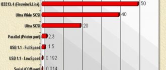
A clear demonstration of the advantages of USB 2.0 over other interfaces (transfer speed 60 MB per second, which corresponds to 480 Mbit per second).
Thanks to full hardware compatibility with the younger version, peripheral devices of this standard can be connected to the previous modification. True, the throughput will decrease up to 35-40 times, and in some cases more.
Since these versions are fully compatible, their cables and connectors are identical.
Please note that, despite the bandwidth specified in the specification, the actual data exchange speed in the second generation is somewhat lower (about 30-35 MB per second). This is due to the implementation of the protocol, which leads to delays between data packets. Since modern drives have a read speed four times higher than the throughput of the second modification, that is, it does not meet current requirements.
- The 3rd generation universal bus was developed specifically to solve problems of insufficient bandwidth. According to the specification, this modification is capable of exchanging information at a speed of 5.0 Gbit per second, which is almost three times the reading speed of modern drives. Plugs and sockets of the latest modification are usually marked blue to facilitate identification of belonging to this specification.
USB 3.0 connectors have a characteristic blue color.
Another feature of the third generation is an increase in the rated current to 0.9 A, which allows you to power a number of devices and eliminate the need for separate power supplies for them.
As for compatibility with the previous version, it is partially implemented; this will be discussed in detail below.
Functions of the “legs” of the micro USB connector
Finally, it’s worth considering the cord for charging your phone. This will help when repairing or diagnosing breakdowns.
It’s worth starting with the positive “red” contact. Electricity “flows” through it when charging a phone or connecting to a computer. In the first case, they can transmit up to 0.5 amperes per hour in the second generation. When connected to a computer, their throughput is limited to 0.25 amperes per hour. Therefore, charging is much slower.
There is no negative contact here, as such. Ground-GND is used instead. It breaks quite rarely, and even if it breaks, this function is taken over by the housing, since it is also grounded.
Near the ground pin there is an inactive pin intended for OTG. However, if it is damaged, the cable will not work, since it performs a shielding function. Moreover, the phone screen may display the charging process, which is not happening! But most often the wire simply does not charge the device.
The remaining two contacts are reserved for data transfer. USB sends data through them. They are designated Data+ and Data-. If one breaks down, the second one does not work, because they also obey the law of potential difference.
On the board, the tracks from them go directly to the memory chip, and “information electrons” fill the necessary cells. They work in both directions: they can transmit data to or receive data from a computer.
In the third generation, the data transfer algorithm was revised, so the contacts were separated. This division contributed to:
- Increasing speed. Theoretically, the third generation can work 10 times faster than the second! USB 2.0 is limited to 480 Mbps, while 3.0 is limited to 4.7 Gbps.
- Duplex connection. At the same time, you can both receive data and transmit it.
The GND Drain leg often does not perform any function. The “signal ground” is often connected directly to the common contact and is not wired. In other cases, it serves as a ground contact for data transmission.
Likewise, the throughput was increased by 0.9 amperes, which is almost 2 times higher. However, the maximum cable length, compared to the second version, is limited to only 3 meters.
Classification and pinout
Connectors are usually classified by type, there are only two of them:
- A is a plug connected to the female socket installed on the PC system board or USB hub. Using this type of connection, you can connect a USB flash drive, keyboard, mouse, etc. These connections are fully compatible between the initial version and the second generation. With the latest modification, compatibility is partial, that is, devices and cables from earlier versions can be connected to third-generation sockets, but not vice versa.
Type A connectors - B – plug for connecting to a socket installed on a peripheral device, for example, a printer. The dimensions of the classic type B do not allow it to be used for connecting small-sized devices (for example, tablets, mobile phones, digital cameras, etc.). To correct the situation, two standard reduced modifications of type B were adopted: mini and micro USB.
Note that such convectors are compatible only between earlier modifications.
Various Type B Connector Models
In addition, there are extension cables for the ports of this interface. At one end there is a type A plug, and at the other there is a socket for it, that is, in fact, a “female” - “male” connection. Such cords can be very useful, for example, to connect a flash drive without crawling under the table to the system unit.
USB Extension Cable
Now let's look at how contacts are wired for each of the types listed above.
Connector types
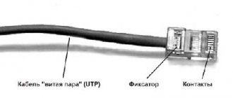
A universal cable will still refer not to the types, but to the types of the popular connector. The path to it was long:
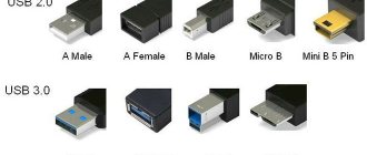
- Type A 2.0. The most popular USB connector was developed back in the mid-nineties. This is a fairly robust design that can withstand a large number of connections/disconnections. Until now, keyboards, mice, web cameras, flash drives and other components are equipped with this connector.
- Type B 2.0. A miniature version of the connector with a square shape. Although its dimensions were reduced, the version still remained large for many devices. Because of this, type B has become more popular among large office equipment - for printers, scanners, etc.
- Mini-type B 2.0. As electronics moved towards compactness, the previous development appeared in an even smaller version. External hard drives and pocket computers were equipped with just such a connector. But it had a significant drawback - low reliability.
- Micro-USB 2.0, type B. Here it is, a universal micro-USB cable. What made it stand out from previous mini-designs was its robust design and smaller size. The invention was equipped with a modernized plug mount that prevented it from becoming loose and falling out of the socket. It has become an ideal solution for modern gadgets.
USB 2.0 connector pinout (types A and B)
Since the physical plugs and sockets of early versions 1.1 and 2.0 do not differ from each other, we will present the wiring of the latter.
Figure 6. Wiring the plug and socket of type A connector
Designation:
- A – nest.
- B – plug.
- 1 – power supply +5.0 V.
- 2 and 3 signal wires.
- 4 – mass.
In the figure, the coloring of the contacts is shown according to the colors of the wire, and corresponds to the accepted specification.
Now let's look at the wiring of the classic socket B.
Wiring of plug and socket type B
Designation:
- A – plug connected to the socket on peripheral devices.
- B – socket on a peripheral device.
- 1 – power contact (+5 V).
- 2 and 3 – signal contacts.
- 4 – ground wire contact.
The colors of the contacts correspond to the accepted colors of the wires in the cord.
Technical characteristics of each model
The first model is USB 1.0. This specification distinguishes two operating modes:
- Low bandwidth.
- With high throughput.
The maximum cable length allowed in this model for the first operating mode is three meters, and for the second operating mode it reaches five meters. If you want to connect several devices, you can connect up to 127 of them.
The technical characteristics of the USB 1.1 model correspond to the first, but all the problems and errors that arose during its use have been corrected. By the way, this is the first model that gained wide popularity
and spread quickly.
The third model is USB 2.0. There are three operating modes for it, where mice, a joystick, gamepads, and a keyboard can be used, as well as video devices and devices that store information.
USB 3.0 pinout (types A and B)
In the third generation, peripheral devices are connected via 10 (9 if there is no shielding braid) wires; accordingly, the number of contacts is also increased. But they are located in such a way that it is possible to connect devices of earlier generations. That is, the +5.0 V contacts, GND, D+ and D-, are located in the same way as in the previous version. The wiring for Type A socket is shown in the figure below.
Figure 8. Pinout of Type A connector in USB 3.0
Designation:
- A – plug.
- B – nest.
- 1, 2, 3, 4 – connectors fully correspond to the pinout of the plug for version 2.0 (see B in Fig. 6), the colors of the wires also match.
- 5 (SS_TX-) and 6 (SS_TX+) connectors for data transmission wires via the SUPER_SPEED protocol.
- 7 – ground (GND) for signal wires.
- 8 (SS_RX-) and 9 (SS_RX+) connectors for data receiving wires using the SUPER_SPEED protocol.
The colors in the figure correspond to those generally accepted for this standard.
As mentioned above, a plug from an earlier model can be inserted into the socket of this port; accordingly, the throughput will decrease. As for the plug of the third generation of the universal bus, it is impossible to insert it into the sockets of the early release.
Now let's look at the pinout for the type B socket. Unlike the previous type, such a socket is incompatible with any plug of earlier versions.
Wiring USB 3.0 type B
Designations:
A and B are plug and socket, respectively.
Digital signatures for contacts correspond to the description in Figure 8.
The color is as close as possible to the color markings of the wires in the cord.
Consequences of incorrect connector replacement
Having soldered micro-USB incorrectly, owners most often encounter the following problems:
- Short circuits of the power supply if they soldered the inverted type.
- The tablet detects the charging cord, but the battery (battery) does not charge.
- The tablet's battery charges perfectly, but it does not sync with a laptop or computer.
- The tablet works fine, but sometimes it “reminds” you that you should take it to a workshop instead of soldering it yourself (for example, charging does not start immediately after turning it on, or sometimes the cord needs to be pulled out and reinserted several times before charging starts) .
Micro USB connector pinout
To begin with, we present the wiring for this specification.
Micro USB v 2.0 connector wiring
As can be seen from the figure, this is a 5 pin connection; both the plug (A) and socket (B) have four contacts. Their purpose and digital and color designation correspond to the accepted standard, which was given above.
Description of the micro USB connector for version 3.0.
For this connection, a characteristically shaped 10 pin connector is used. In fact, it consists of two parts of 5 pin each, and one of them fully corresponds to the previous version of the interface. This implementation is somewhat confusing, especially considering the incompatibility of these types. Probably, the developers planned to make it possible to work with connectors of earlier modifications, but subsequently abandoned this idea or have not yet implemented it.
MicroUSB connector layout for version 3.0
The figure shows the pinout of the plug (A) and the appearance of the micro USB socket (B).
Contacts 1 to 5 fully correspond to the second generation micro connector, the purpose of the other contacts is as follows:
- 6 and 7 – data transmission via high-speed protocol (SS_TX- and SS_TX+, respectively).
- 8 – mass for high-speed information channels.
- 9 and 10 – data reception via high-speed protocol (SS_RX- and SS_RX+, respectively).
Design and purpose of the cable
We continue our review of micro-USB cables. Let's now look directly at their device.
Each cable has four wires as standard. The main differences between the devices are in the end switches, which can differ significantly in the purpose of the model.
The cost of the cable is significantly influenced by the following characteristics: length and thickness of the wire, the presence of an insulating layer, ferrite filters, additional cores, and type of braiding material.
Here are some popular examples of limit switches. They are as follows:
- One is micro-USB type B, the second is USB type A (2.0). In fact, this is an adapter from one type of device to another. For example, it is used to connect between a tablet, phone and personal computer.
- Switch to USB 2.0 A OTG. Used to connect two media with each other. In particular, using such a cable you can connect a flash drive to a smartphone.
- Variations to transmit a specific power supply, a specific type of data.
Mini USB pinout
This connection option is used only in early versions of the interface; in the third generation this type is not used.
Mini USB connector pinout
As you can see, the wiring of the plug and socket is almost identical to the micro USB, respectively, the color scheme of the wires and the contact numbers are also the same. Actually, the differences are only in shape and size.
In this article we have presented only standard types of connections; many manufacturers of digital equipment practice introducing their own standards; there you can find connectors for 7 pin, 8 pin, etc. This introduces certain difficulties, especially when the question arises of finding a charger for a mobile phone. It should also be noted that products are in no hurry to tell how the USB pinout is done in such contactors. But, as a rule, this information is easy to find on thematic forums.