Introduction
If someone came up with the idea of conducting a survey of the world's population on the topic “What do you know about inductance?”, the overwhelming number of respondents would simply shrug their shoulders. But this is the second most numerous technical element, after transistors, on which modern civilization is based! Detective fans, remembering that in their youth they read Sir Arthur Conan Doyle’s exciting stories about the adventures of the famous detective Sherlock Holmes, will, with varying degrees of confidence, mutter something about the method that the above-mentioned detective used. At the same time, implying the method of deduction, which, along with the method of induction, is the main method of knowledge in Western philosophy of the New Age.
With the induction method, individual facts, principles are studied and general theoretical concepts are formed based on the results obtained (from particular to general). The deduction method, on the contrary, involves research from general principles and laws, when the provisions of the theory are distributed into individual phenomena.
It should be noted that induction, in the sense of method, does not have any direct relation to inductance, they simply have a common Latin root inductio
- guidance, motivation - and mean completely different concepts.
Only a small part of those surveyed from among the exact sciences - professional physicists, electrical engineers, radio engineers and students in these fields - will be able to give a clear answer to this question, and some of them are ready to give an entire lecture on this topic right away.
Definition of inductance
In physics, inductance, or the coefficient of self-induction, is defined as the coefficient of proportionality L between the magnetic flux Ф around a current-carrying conductor and the current I generating it, or - in a more strict formulation - this is the coefficient of proportionality between the electric current flowing in any closed circuit and the magnetic flux created by this current:
Ф = L·I
or
L = Ф/I
To understand the physical role of the inductor in electrical circuits, one can use the analogy of the formula for the energy stored in it when current I flows with the formula for the mechanical kinetic energy of the body.
For a given current I, inductance L determines the energy of the magnetic field W created by this current I:
WI
= 1/2
L
I
2
Similarly, the mechanical kinetic energy of a body is determined by the mass of the body m and its speed V:
Wk
= 1/2 ·
m
·
V
2
That is, inductance, like mass, does not allow the energy of the magnetic field to instantly increase, just as mass does not allow this to happen with the kinetic energy of the body.
Let's study the behavior of current in inductance:
Rice. 1. Electrical diagram of the experiment
Rice. 2. Physical implementation of the experiment
Rice. 3. Oscillogram of current through inductance. The yellow oscillogram is the output of the signal generator, the blue one is the signal at the resistor.
Due to the inertia of the inductance, the fronts of the input voltage are delayed. In automation and radio engineering, such a circuit is called an integrating circuit, and is used to perform the mathematical operation of integration.
Let's study the voltage on the inductor:
Rice. 4. Electrical diagram of the experiment
Rice. 6. Voltage oscillogram across the inductance (blue)
At the moments of applying and removing voltage, due to the self-inductive emf inherent in the inductance coils, voltage surges occur. Such a circuit in automation and radio engineering is called differentiating, and is used in automation to correct processes in a controlled object that are fast in nature.
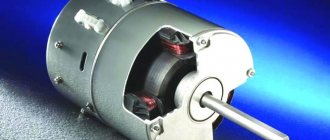
Rice. 5. By and large, in all electric current generators of any type, as well as in electric motors, their windings are inductor coils.
Inductance and capacitance in an alternating current circuit
Changes in current, voltage, etc. d.s. in an alternating current circuit occur with the same frequency, but the phases of these changes are, generally speaking, different. Therefore, if the initial phase of the current strength is conventionally taken as zero, then the initial phases of voltage and e. d.s. respectively will have some values of ϕ and ψ. Under this condition, the instantaneous values of current, voltage, etc. d.s. will be expressed by the following formulas:
i = Im sin ωt
u = Uм sin (ϕ + ωt),
e = Ɛm sin (ψ + ωt).
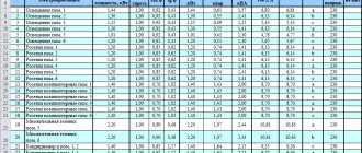
The circuit resistance, which causes irretrievable loss of electrical energy due to the thermal effect of current, is called active. This resistance for low frequency current can be considered equal to the resistance R of the same conductor to direct current and can be found using the formula:
R=(pl/S)(1 + at).
In an alternating current circuit that has only active resistance, for example in incandescent lamps, heating devices, etc., the phase shift between voltage and current is zero, i.e. ϕ = 0. This means that the current and voltage in such a circuit change in the same phases, and the electrical energy is completely spent on the thermal effect of the current.
Connection diagram and diagram
The inclusion of a coil with inductance L in an alternating current circuit manifests itself as an increase in the resistance of the circuit. This is explained by the fact that with alternating current the e is always active in the coil. d.s. self-induction, weakening the current. Resistance XL, which is determined by the phenomenon of self-induction, is called inductive resistance. Since e. d.s. self-inductance is greater, the greater the inductance of the circuit and the faster the current changes, then the inductive reactance is directly proportional to the inductance of the circuit L and the circular frequency of the alternating current ω:
ХL = ωL.
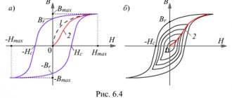
The effect of inductive reactance on the current strength in a circuit is clearly illustrated by the experiment shown in Fig. 26.6. When the ferromagnetic core is lowered into the coil, the lamp goes out, and when it is removed, it lights up again. This is explained by the fact that the inductance of the coil increases greatly when a core is introduced into it. It should be noted that the voltage across the inductive reactance is ahead of the current in phase.
Direct current does not pass through the capacitor, since there is a dielectric between its plates. If a capacitor is connected to a DC circuit, then after charging the capacitor, the current in the circuit will stop.
Inductors
Let the capacitor be connected to an alternating current circuit. The charge on the capacitor (q=CU) changes continuously due to voltage changes, so alternating current flows in the circuit. The greater the capacitance of the capacitor and the more often it is recharged, i.e., the greater the frequency of the alternating current, the greater the current strength. The resistance caused by the presence of electrical capacitance in the alternating current circuit is called capacitive reactance Xc. It is inversely proportional to the capacitance C and the angular frequency ω;
Xc = 1/ωС
From a comparison of formulas (26.11) and (26.12) it is clear that inductors represent a very large resistance for high-frequency current and small resistance for low-frequency current, and capacitors - vice versa. The voltage across the capacitive reactance Xa lags in phase with the current. Inductive XL and capacitive XC resistances are called reactive. In the theory of alternating current, it is proven that when inductive and capacitive reactances are connected in series, the total reactance is equal to their difference:
It will be interesting➡ What is step voltage and why is it dangerous?
X = XL—XC
and has an inductive character for XL > Xc and a capacitive character for XL < Xc.
In conclusion, we note that the average active power of alternating current, showing how much energy per unit time is transferred by electric current to a given section of the circuit, is determined by the formula:
P = IU cos ϕ.
The power expended only on the thermal effect of the current is expressed by the formula:
P = I2R
To increase the active power of alternating current, you need to increase cos ϕ. (Explain why cos ϕ has the greatest value at XL=XC.)
Inductance
Units
In the SI system of units, inductance is measured in henry, abbreviated as Hn. A circuit carrying current has an inductance of one henry if, when the current changes by one ampere per second, a voltage of one volt appears at the terminals of the circuit.
In variants of the SGS system - the SGSM system and in the Gaussian system, inductance is measured in centimeters (1 Hn = 10⁹ cm; 1 cm = 1 nH); For centimeters, the name abhenry is also used as a unit of inductance. In the SGSE system, the unit of measurement of inductance is either left nameless or sometimes called stathenry (1 stathenry ≈ 8.987552•10⁻¹¹ henry, the conversion factor is numerically equal to 10⁻⁹ the square of the speed of light, expressed in cm/s).
INDUCTANCE
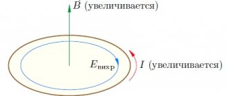
Electric current creates its own magnetic field. The magnetic flux through the circuit is proportional to the magnetic field induction (Ф ~ B), the induction is proportional to the current strength in the conductor (B ~ I), therefore the magnetic flux is proportional to the current strength (Ф ~ I).
The self-induction emf depends on the rate of change of current in the electrical circuit, on the properties of the conductor (size and shape) and on the relative magnetic permeability of the medium in which the conductor is located.
A physical quantity showing the dependence of the self-induction emf on the size and shape of the conductor and on the environment in which the conductor is located is called the self-induction coefficient or inductance.
Inductance - physical. a value numerically equal to the self-inductive emf that occurs in the circuit when the current changes by 1 Ampere in 1 second.
Inductance can also be calculated using the formula:
where Ф is the magnetic flux through the circuit, I is the current strength in the circuit.
SI units of inductance:
The inductance of the coil depends on: the number of turns, the size and shape of the coil and the relative magnetic permeability of the medium
(core possible).
Mutual inductance is a quantity characterizing the magnetic coupling of two or more electrical circuits (circuits). If there are two conducting circuits, then part of the magnetic induction lines created by the current in the first circuit will penetrate the area limited by the second circuit (i.e., it will be linked to circuit 2).
Magnetic flux Ф12 through circuit 2, created by current I1 in circuit 1, is directly proportional to the current:
The proportionality coefficient M12 depends on the size and shape of circuits 1 and 2, the distance between them, their relative position, as well as the magnetic permeability of the environment and is called mutual inductance or the coefficient of mutual induction of circuits 1 and 2. In the SI system I.V. measured in Henry.
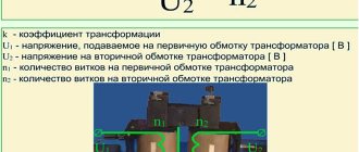
Transformer EMF. The operating principle of the transformer is based on the phenomenon of electromagnetic induction. The induction lines of the magnetic field created by alternating current in the primary winding, thanks to the presence of the core, penetrate the turns of the secondary winding with virtually no losses. Since the magnetic flux in the secondary winding changes with time (since there is alternating current in the primary winding), according to Faraday’s law, an induced emf is excited in it. The transformer can only operate on alternating current, because the magnetic flux created by direct current does not change over time.
Let the primary winding of the transformer be connected to a current source with a variable emf E1 and an effective voltage value U1. On the secondary winding there is EMF E2 and voltage U2.
From Ohm's laws it follows that the voltage on the winding is equal to
(1)
where r is the winding resistance. When manufacturing a transformer, the resistance of the primary winding r1 is made very small, so it can often be neglected. Then
If we neglect the losses of magnetic flux in the core, then exactly the same induced emf e1 will be induced in each turn of the secondary winding as the induced emf e2 in each turn of the primary winding, i.e. e1 = e2. Consequently, the ratio of the EMF in the primary E1 and secondary E2 windings is equal to the ratio of the number of turns in them:
(2)
Transformer current. Winding currents are inversely proportional to the number of turns (I1/I2 approx = w1/w2 = 1/n). As the active-inductive receiver current increases, the secondary voltage decreases slightly.
Dissipation flow.
Fig.1.11. To determine the magnetic leakage flux in a coil with a ferromagnetic core
part of the magnetic flux of the coil is closed not through the core, but through the air. This part of the flow is called the dissipation flow Fr (Fig. 1.11). Thus, the total flux associated with the turns of the coil is equal to
| . | (1.14) |
Based on Ohm's law for a magnetic circuit (1.7), we can write an expression for the leakage flux:
| . |
Since, then. That is, the leakage flux, in contrast to the flux in the core, is in phase with the current and is related to it by a linear dependence. Consequently, in the vector diagram, the flux vector will coincide with the current vector (Fig. 1.12).
Fig.1.12. Vector diagram of magnetic fluxes, emf and currents of a coil with a ferromagnetic core
Electric current creates its own magnetic field. The magnetic flux through the circuit is proportional to the magnetic field induction (Ф ~ B), the induction is proportional to the current strength in the conductor (B ~ I), therefore the magnetic flux is proportional to the current strength (Ф ~ I).
The self-induction emf depends on the rate of change of current in the electrical circuit, on the properties of the conductor (size and shape) and on the relative magnetic permeability of the medium in which the conductor is located.
A physical quantity showing the dependence of the self-induction emf on the size and shape of the conductor and on the environment in which the conductor is located is called the self-induction coefficient or inductance.
Inductance - physical. a value numerically equal to the self-inductive emf that occurs in the circuit when the current changes by 1 Ampere in 1 second.
Inductance can also be calculated using the formula:
where Ф is the magnetic flux through the circuit, I is the current strength in the circuit.
SI units of inductance:
The inductance of the coil depends on: the number of turns, the size and shape of the coil and the relative magnetic permeability of the medium
(core possible).
Mutual inductance is a quantity characterizing the magnetic coupling of two or more electrical circuits (circuits). If there are two conducting circuits, then part of the magnetic induction lines created by the current in the first circuit will penetrate the area limited by the second circuit (i.e., it will be linked to circuit 2).
Magnetic flux Ф12 through circuit 2, created by current I1 in circuit 1, is directly proportional to the current:
The proportionality coefficient M12 depends on the size and shape of circuits 1 and 2, the distance between them, their relative position, as well as the magnetic permeability of the environment and is called mutual inductance or the coefficient of mutual induction of circuits 1 and 2. In the SI system I.V. measured in Henry.
Transformer EMF. The operating principle of the transformer is based on the phenomenon of electromagnetic induction. The induction lines of the magnetic field created by alternating current in the primary winding, thanks to the presence of the core, penetrate the turns of the secondary winding with virtually no losses. Since the magnetic flux in the secondary winding changes with time (since there is alternating current in the primary winding), according to Faraday’s law, an induced emf is excited in it. The transformer can only operate on alternating current, because the magnetic flux created by direct current does not change over time.
Let the primary winding of the transformer be connected to a current source with a variable emf E1 and an effective voltage value U1. On the secondary winding there is EMF E2 and voltage U2.
From Ohm's laws it follows that the voltage on the winding is equal to
(1)
where r is the winding resistance. When manufacturing a transformer, the resistance of the primary winding r1 is made very small, so it can often be neglected. Then
If we neglect the losses of magnetic flux in the core, then exactly the same induced emf e1 will be induced in each turn of the secondary winding as the induced emf e2 in each turn of the primary winding, i.e. e1 = e2. Consequently, the ratio of the EMF in the primary E1 and secondary E2 windings is equal to the ratio of the number of turns in them:
(2)
Transformer current. Winding currents are inversely proportional to the number of turns (I1/I2 approx = w1/w2 = 1/n). As the active-inductive receiver current increases, the secondary voltage decreases slightly.
Dissipation flow.
Fig.1.11. To determine the magnetic leakage flux in a coil with a ferromagnetic core
part of the magnetic flux of the coil is closed not through the core, but through the air. This part of the flow is called the dissipation flow Fr (Fig. 1.11). Thus, the total flux associated with the turns of the coil is equal to
| . | (1.14) |
Based on Ohm's law for a magnetic circuit (1.7), we can write an expression for the leakage flux:
| . |
Since, then. That is, the leakage flux, in contrast to the flux in the core, is in phase with the current and is related to it by a linear dependence. Consequently, in the vector diagram, the flux vector will coincide with the current vector (Fig. 1.12).
Fig.1.12. Vector diagram of magnetic fluxes, emf and currents of a coil with a ferromagnetic core
Historical reference
The symbol L used to denote inductance was adopted in honor of Heinrich Friedrich Emil Lenz, who is known for his contributions to the study of electromagnetism, and who derived Lenz's rule on the properties of induced current. The unit of inductance is named after Joseph Henry, who discovered self-inductance. The term inductance itself was coined by Oliver Heaviside in February 1886.
Among the scientists who took part in the study of the properties of inductance and the development of its various applications, it is necessary to mention Sir Henry Cavendish, who conducted experiments with electricity; Michael Faraday, who discovered electromagnetic induction; Nikola Tesla, who is famous for his work on electrical transmission systems; André-Marie Ampere, who is considered the discoverer of the theory of electromagnetism; Gustav Robert Kirchhoff, who studied electrical circuits; James Clark Maxwell, who studied electromagnetic fields and their particular examples: electricity, magnetism and optics; Henry Rudolf Hertz, who proved that electromagnetic waves do exist; Albert Abraham Michelson and Robert Andrews Millikan. Of course, all these scientists studied other problems that are not mentioned here.
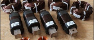
Inductor
By definition, an inductor is a helical, helical, or helical coil of coiled insulated conductor that has significant inductance with a relatively small capacitance and low active resistance. As a result, when an alternating electric current flows through the coil, its significant inertia is observed, which can be observed in the experiment described above. In high-frequency technology, an inductor can consist of one turn or part of it; in the extreme case, at ultra-high frequencies, a piece of conductor is used to create inductance, which has the so-called distributed inductance (strip lines).
Application in technology
Inductors are used:
Rice. 9. Inductors
- For noise suppression, ripple smoothing, energy storage, alternating current limitation, in resonant (oscillating circuit) and frequency-selective circuits; creating magnetic fields, motion sensors, in credit card readers, as well as in contactless credit cards themselves.
- Inductors (together with capacitors and resistors) are used to construct various circuits with frequency-dependent properties, in particular filters, feedback circuits, oscillating circuits and others. Such coils, accordingly, are called: contour coil, filter coil, and so on.
- Two inductively coupled coils form a transformer.
- An inductor, powered by a pulsed current from a transistor switch, is sometimes used as a high-voltage source of low power in low-current circuits when creating a separate high supply voltage in the power supply is impossible or economically impractical. In this case, high voltage surges appear on the coil due to self-induction, which can be used in the circuit.
- When used to suppress interference, smooth out electrical current ripples, isolate (high-frequency) different parts of the circuit, and store energy in the magnetic field of the core, an inductor is called an inductor.
- In power electrical engineering (to limit the current during, for example, a short circuit of a power line), an inductor is called a reactor.
- Current limiters for welding machines are made in the form of an inductance coil, limiting the current of the welding arc and making it more stable, thereby allowing for a more even and durable weld.
- Inductors are also used as electromagnets - actuators. A cylindrical inductor whose length is much greater than its diameter is called a solenoid. In addition, a solenoid is often called a device that performs mechanical work due to a magnetic field when a ferromagnetic core is retracted.
- In electromagnetic relays, the inductors are called relay windings.
- A heating inductor is a special inductor coil, the working element of induction heating installations and kitchen induction ovens.
By and large, in all electric current generators of any type, as well as in electric motors, their windings are inductor coils. Following the ancient tradition of depicting a flat Earth standing on three elephants or whales, today we could with greater justification assert that life on Earth rests on an inductive coil.
Rice. 15. Earth's magnetosphere
After all, even the Earth’s magnetic field, which protects all terrestrial organisms from corpuscular cosmic and solar radiation, according to the main hypothesis about its origin, is associated with the flow of huge currents in the liquid metal core of the Earth. In essence, this core is a planetary-scale inductor. It is calculated that the zone in which the “magnetic dynamo” mechanism operates is located at a distance of 0.25-0.3 Earth radii.
Rice. 7. Magnetic field around a current-carrying conductor. I
— current,
B
— magnetic induction vector.
Inductance in AC circuit
The passage of electric current through a conductor or coil is accompanied by the appearance of a magnetic field. Let's consider an alternating current electrical circuit, which includes an inductor with a small number of turns of wire of a relatively large cross-section, the active resistance of which can be considered almost equal to zero. Under the influence of e. d.s. generator, an alternating current flows in the circuit, exciting an alternating magnetic flux. This flow crosses the “own” turns of the coil and an electromotive force of self-induction arises in it
The electromotive force of self-induction, according to Lenz's rule, always counteracts the cause that causes it. Since e. d.s. self-induction always counteracts changes in alternating current caused by e. d.s. generator, it prevents the passage of alternating current. In calculations, this is taken into account by inductive reactance, which is designated XL and measured in ohms.
Measuring an inductor with a multimeter
Thus, the inductive reactance of the XL coil depends on the value of e. d.s. self-induction, and therefore it, like e. d.s. self-induction, depends on the rate of change of current in the coil (on frequency ω) and on the inductance of the coil L
XL = ωL,
- where XL is inductive reactance, ohm;
- ω—angular frequency of alternating current, rad/sec;
- L—coil inductance, Hz.
Since the angular frequency of alternating current is ω = 2πf, then the inductive reactance
XL = 2πf L, (59)
where f is the frequency of alternating current, Hz.
Inductance is an idealized element of an electrical circuit in which magnetic field energy is stored. There is no storage of electric field energy or conversion of electrical energy into other types of energy.
Example. A coil with an inductance L = 0.5 H is connected to an alternating current source whose frequency is f = 50 Hz. Determine: 1) the inductive reactance of the coil at frequency f = 50 Hz; 2) the inductive resistance of this coil to alternating current, the frequency of which is f = 800 Hz. Solution. Inductive reactance to alternating current at f = 50 Hz
XL = 2πf L = 2 3.14 50 0.5 = 157 ohms.
At current frequency f = 800 Hz
XL = 2πf L = 2 3.14 800 0.5 = 2512 ohms.
Welding arc inductance
The above example shows that the inductive reactance of a coil increases with increasing frequency of the alternating current flowing through it. As the frequency of the current decreases, the inductive reactance decreases. For direct current, when the current in the coil does not change and the magnetic flux does not cross its turns, e.g. d.s. self-induction does not occur, the inductive reactance of the XL coil is zero. The inductor for direct current is only a resistance
Let's find out how z changes. d.s. self-induction, when alternating current flows through the inductor. It is known that with a constant coil inductance e. d.s. self-induction depends on the rate of change in current strength and it is always directed towards the cause that caused it.
In the first quarter of the period, the current increases from zero to maximum value. The electromotive force of self-induction ec, according to Lenz's rule, prevents an increase in current in the circuit. Therefore, the graph (dashed line) shows that ec at this time has a negative value. In the second quarter of the period, the current in the coil decreases to zero. At this time e. d.s. self-induction changes its direction and increases, preventing the current from decreasing. In the third quarter of the period, the current changes its direction and gradually increases to its maximum value; e. d.s. self-induction has a positive value further, when the current strength decreases, e. d.s. self-induction again changes its direction and again prevents the current from decreasing in the circuit.
Inductance
From the above it follows that the current in the circuit and e. d.s. self-inductions are out of phase. The current is ahead of the e. d.s. self-induction in phase by a quarter of a period or by an angle φ = 90°. It must also be borne in mind that in a circuit with an inductance that does not contain r, at each moment of time the electromotive force of self-induction is directed towards the generator voltage U. In this regard, the voltage and e. d.s. The self-inductances ec are also phase-shifted relative to each other by 180°.
It will be interesting➡ What is current density?
From the foregoing it follows that in an alternating current circuit containing only inductance, the current lags behind the voltage generated by the generator by an angle φ = 90° (a quarter of a period) and is ahead of e. d.s. self-induction by 90°. We can also say that in an inductive circuit the voltage is 90° ahead of the current in phase. Let's construct a vector diagram of current and voltage for an alternating current circuit with inductive reactance. To do this, let us plot the current vector I horizontally on the scale we have chosen.
To show on a vector diagram that the voltage is ahead of the current in phase by an angle φ = 90°, we plot the voltage vector U upward at an angle of 90°. Ohm's law for a circuit with inductance can be expressed as follows:
It should be emphasized that there is a significant difference between inductive and active resistance to alternating current. When a resistive load is connected to an alternator, energy is irretrievably consumed by the resistive resistance.
If an inductive reactance r = 0 is connected to an alternating current source, then its energy, while the current strength increases, is spent on exciting a magnetic field. Changing this field causes e. d.s. self-induction. When the current decreases, the energy stored in the magnetic field due to the resulting e. d.s. self-induction is returned back to the generator.
- In the first quarter of the period, the current strength in the circuit with inductance increases and the energy of the current source accumulates in the magnetic field. At this time e. d.s. self-induction is directed against voltage.
- When the current reaches its maximum value and begins to decrease in the second quarter of the period, then e.g. d.s. self-induction, changing its direction, tends to maintain the current in the circuit. Under the influence of e. d.s. Self-induction, the energy of the magnetic field returns to the energy source - the generator. At this time, the generator operates in engine mode, converting electrical energy into mechanical energy.
- In the third quarter of the period, the current strength in the circuit under the influence of e. d.s. the generator increases, and at the same time the current flows in the opposite direction. At this time, the energy of the generator is again accumulated in the magnetic field of inductance.
- In the fourth quarter of the period, the current strength in the circuit decreases, and the energy accumulated in the magnetic field under the influence of e. d.s. self-induction is returned to the generator again.
Thus, in the first and third quarter of each period, the alternator spends its energy in a circuit with inductance to create a magnetic field, and in the second and fourth quarter of each period, the energy stored in the magnetic field of the coil as a result of the resulting e. d.s. self-induction, returns back to the generator.
Interesting on the topic: How to check a zener diode.
It follows from this that an inductive load, unlike an active load, on average does not consume the energy generated by the generator, and in a circuit with inductance, energy is “pumped” from the generator to the inductive load and back, i.e., energy fluctuations occur. From the above it follows that inductive reactance is reactive. In a circuit containing reactance, energy oscillates from the generator to the load and back.
It will be interesting➡ What is a bridge rectifier and how does it work?