The author of the article is a professional tutor, author of textbooks for preparing for the Unified State Exam Igor Vyacheslavovich Yakovlev
Topics of the Unified State Examination codifier: self-induction, inductance, magnetic field energy.
Self-induction is a special case of electromagnetic induction. It turns out that the electric current in the circuit, changing over time, influences itself in a certain way.
Situation 1
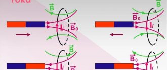
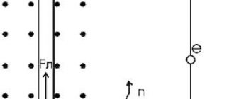
.Suppose that the current in the circuit increases. Let the current flow counterclockwise; then the magnetic field of this current is directed upward and increases (Fig. 1).
Rice. 1. The vortex field prevents the current from increasing
Thus, our circuit finds itself in the alternating magnetic field of its own current. The magnetic field in this case increases (together with the current) and therefore generates a vortex electric field, the lines of which are directed clockwise in accordance with Lenz’s rule.
As we see, the vortex electric field is directed against the current, preventing its increase; it seems to “slow down” the current. Therefore, when any circuit is closed, the current is not established instantly; it takes some time to overcome the braking effect of the resulting vortex electric field.
Situation 2
. Let us now assume that the current in the circuit decreases. The magnetic field of the current also decreases and generates a vortex electric field directed counterclockwise (Fig. 2).
Rice. 2. The vortex field maintains a decreasing current
Now the vortex electric field is directed in the same direction as the current; it maintains the current, preventing it from decreasing.
As we know, the work of an eddy electric field to move a unit positive charge around a circuit is the induced emf. Therefore we can give this definition.
The phenomenon of self-induction is that when the current in a circuit changes, an induced emf occurs in the same circuit
.
As the current strength increases (in situation 1), the vortex electric field does negative work, braking free charges. Therefore, the induced emf in this case is negative.
When the current strength decreases (in situation 2), the vortex electric field does positive work, “pushing” free charges and preventing the current from decreasing. The induced emf in this case is also positive (it is easy to verify that the sign of the induced emf, determined in this way, is consistent with the rule for choosing the sign for the induced emf, formulated in the sheet “Electromagnetic induction”).
Inductance
We know that the magnetic flux passing through the circuit is proportional to the magnetic field induction: . In addition, experience shows that the magnitude of the magnetic field induction of a circuit with current is proportional to the strength of the current: Therefore, the magnetic flux through the surface of the circuit, created by the magnetic field of the current in this very circuit, is proportional to the strength of the current: The proportionality coefficient is designated and called the inductance of the circuit:
(1)
Inductance depends on the geometric properties of the circuit (shape and size), as well as on the magnetic properties of the medium in which the circuit is placed (Do you catch the analogy? The capacitance of a capacitor depends on its geometric characteristics, as well as on the dielectric constant of the medium between the plates of the capacitor). The unit of inductance is henry (H).
Let us assume that the shape of the circuit, its dimensions and the magnetic properties of the medium remain constant (for example, our circuit is a coil into which a core is not inserted); The change in magnetic flux through the circuit is caused only by the change in current. Then, and Faraday’s law takes the form:
(2)
Thanks to the minus sign in (2), the induced emf turns out to be negative when the current increases and positive when the current decreases, which we saw above.
Let's consider two experiments demonstrating the phenomenon of self-induction when closing and opening a circuit.
Rice. 3. Self-induction when closing the circuit
In the first experiment, two light bulbs are connected in parallel to a battery, and the second one is connected in series with a coil of sufficiently high inductance (Fig. 3).
The key is initially open.
When the key is closed, light 1 lights up immediately, and light 2 lights up gradually. The fact is that an induced emf appears in the coil, which prevents the current from increasing. Therefore, the maximum current value in the second light bulb is established only after some noticeable time after the first light bulb flashes.
This delay time is greater, the greater the inductance of the coil. The explanation is simple: after all, then the intensity of the vortex electric field arising in the coil will be greater, and therefore the battery will have to do a lot of work to overcome the vortex field that decelerates the charged particles.
In the second experiment, a coil and a light bulb are connected in parallel to the battery (Fig. 4). The resistance of the coil is much less than the resistance of the light bulb.
Rice. 4. Self-induction when the circuit opens
The key is initially closed. The light bulb does not light up - the voltage on it is close to zero due to the low resistance of the coil. Almost all the current flowing in an unbranched circuit passes through the coil.
When the key is opened, the light flashes brightly! Why? The current through the coil begins to decrease sharply, and a significant induced emf arises, supporting the decreasing current (after all, the induced emf, as can be seen from (2), is proportional to the rate of change of the current).
In other words, when the key is opened, a very large vortex electric field appears in the coil, accelerating free charges. Under the influence of this vortex field, a current pulse runs through the light bulb, and we see a bright flash. If the inductance of the coil is sufficiently large, the induced emf can become significantly greater than the emf of the battery, and the light bulb will completely burn out.
You may not mind the light bulb, but in industry and energy this effect is a serious problem. Since when the circuit is opened, the current begins to decrease very quickly, the induced emf arising in the circuit can significantly exceed the rated voltage and reach dangerously large values. Therefore, in units that consume high current, special hardware precautions are provided (for example, oil switches in power plants) to prevent instantaneous opening of the circuit.
Self-induction phenomenon
If a direct current passes through a circuit, then there is a constant magnetic field around the circuit, and the intrinsic magnetic flux passing through the circuit does not change over time.
If the current passing in the circuit changes over time, then the correspondingly changing own magnetic flux, and, according to the law of electromagnetic induction, creates an EMF in the circuit.
- The occurrence of induced emf in a circuit, which is caused by a change in the current strength in this circuit, is called the phenomenon of self-induction
. Self-induction was discovered by the American physicist J. Henry in 1832.
The emf that appears in this case is the self-induction emf Esi. The self-induction emf creates a self-induction current I
si.
The direction of the self-induction current is determined by Lenz's rule: the self-induction current is always directed so that it counteracts the change in the main current. If the main current increases, then the self-induction current is directed against the direction of the main current; if it decreases, then the directions of the main current and the self-induction current coincide.
Using the law of electromagnetic induction for a circuit with inductance L
and equation (1), we obtain the expression for the self-induction emf:
\(E_{si} =-\dfrac{\Delta \Phi }{\Delta t}=-L\cdot \dfrac{\Delta I}{\Delta t} .\)
- The self-induction emf is directly proportional to the rate of change of current in the circuit, taken with the opposite sign. This formula can only be used with a uniform change in current strength. As the current increases (Δ I
> 0), the EMF is negative (Esi < 0), i.e.
the induced current is directed in the opposite direction of the source current. When the current decreases (Δ I
< 0), the EMF is positive (Esi > 0), i.e. the induced current is directed in the same direction as the source current.
From the resulting formula it follows that
\(L=-E_{si} \cdot \dfrac{\Delta t}{\Delta I}.\)
- Inductance
is a physical quantity numerically equal to the self-inductive emf that occurs in the circuit when the current changes by 1 A in 1 s.
The phenomenon of self-induction can be observed in simple experiments. Figure 1 shows a diagram of parallel connection of two identical lamps. One of them is connected to the source through resistor R
the
other in series with the coil
L. When the key is closed, the first lamp flashes almost immediately, and the second - with a noticeable delay. This is explained by the fact that there is no inductance in the section of the circuit with lamp 1
, so there will be no self-induction current, and the current strength in this lamp almost instantly reaches its maximum value.
In the section with lamp 2
, as the current in the circuit increases (from zero to maximum), a self-induction current
Isi
, which prevents a rapid increase in the current in the lamp.
Figure 2 shows an approximate graph of the change in current in lamp 2
when the circuit is closed.
- Rice. 1
- Rice. 2
When the key is opened, the current in the lamp 2
will also fade slowly (Fig. 3, a).
If the inductance of the coil is large enough, then immediately after the switch is opened, there may even be a slight increase in the current (lamp 2
flashes more strongly), and only then the current begins to decrease (Fig. 3, b).
- A
- b
Rice.
3 The phenomenon of self-induction creates a spark at the point where the circuit opens. If there are powerful electromagnets in the circuit, the spark can turn into an arc and damage the switch. To open such circuits, power plants use special switches.
What is self-induction - for dummies
Any electronic conductor has an alternating magnetic field, which generates an additional, so-called induction current. And if we consider an electrical circuit as a conductor, then when the current strength changes in it, the magnetic field will also change, which will provoke the appearance of a vortex electric field.
Such phenomena will cause the appearance of electromotive force (EMF) in the same circuit, which is self-induction. Thus, self-induction is considered a phenomenon during which an EMF occurs in an electrical conductor due to a change in current in the conductor itself. It is self-induction that prevents the current from acquiring a certain value when the electrical circuit is suddenly closed or opened, since the EMF in the conductor during the current increase is directed in the opposite direction relative to the power source and vice versa during its decrease.
The phenomenon of self-induction can be clearly seen when turning on or off 2 identical lamps that are connected in parallel.
In this case, the self-induction emf can be calculated using the formula:
Ɛ=-dФ/dt, where:
- Ɛ – direct EMF;
- dФ – changes in the magnetic field;
- dt – the period of time during which the changes occurred.
EMF is measured in volts when the unit of magnetic field is weber.
Self-induction
Let's imagine any electrical circuit whose parameters can be changed. If we change the current strength in this circuit - for example, we turn up the rheostat or connect another current source - the magnetic field will change. As a result of this change, an additional induced current will arise in the circuit due to electromagnetic induction, which we discussed above. This phenomenon is called self-induction, and the resulting current is called self-induction current.
| Magnetic flux formula for self-induction F = LI Ф - own magnetic flux [Wb] L - circuit inductance [H] I - current strength in the circuit [A] |
Online preparation for the OGE in physics will help you relieve stress before the exam and get a high score.
Self-induction is the occurrence of an EMF in a conducting circuit, created as a result of a change in current strength in the circuit itself.
Self-induction is somewhat reminiscent of inertia: just as in mechanics it is impossible to instantly stop a moving body, so the current cannot instantly acquire a certain value due to self-induction.
Let's imagine a circuit consisting of two identical lamps connected in parallel to a current source. If we connect a coil in series with the second lamp in this circuit, then when the circuit is closed, the following will happen:
- the first lamp will light up almost immediately,
- the second lamp will light up with a noticeable delay.
When the circuit is opened, the current strength quickly decreases, and the resulting self-induction emf prevents the decrease in magnetic flux. In this case, the induced current is directed in the same way as the original one. The self-induced emf can be many times greater than the external emf. This is why light bulbs burn out so often when the lights go out.
| Self-induced emf ξis — self-induction emf [V] ΔФ/Δt — rate of change of magnetic flux [Wb/s] ΔI/Δt - rate of change of current in the circuit [A/s] L - inductance [H] |
The minus sign in the formula for the law of electromagnetic induction indicates that the induced emf prevents the change in magnetic flux, which causes the emf. When solving calculation problems, the minus sign is not taken into account.
About inductance in simple words
Inductance is a physical quantity that was introduced to evaluate the ability of an electrical conductor to resist current. Those. inductance, or as it is also called, the self-inductance coefficient, shows the dependence of Ɛ on the properties of the conductor and on the magnetic permeability of the environment in which it is located. The unit of measurement is henry (H).
If we consider the value using an inductor as an example, we can understand that its performance will vary depending on the number of turns of the coil, as well as its size and shape. The greater the number of turns, the greater the inductance. This value will also be increased if a core is placed inside the coil, since the relative magnetic permeability of the medium in which the conductor is located will change. This relationship can be seen in the diagram.
If you look at the formula for the dependence of EMF on inductance, you can understand that the greater the value, the more noticeable the electromotive force will be, which indicates their direct proportionality. Following from this, we can conclude that inductance acts as a kind of “storage” of energy, which opens at the moment the current changes.
Ɛ=- L(dI/dt), where:
- Ɛ – self-induced emf;
- L-inductance;
- I – current strength;
- t – time.
In this case, L is equal to the magnetic field (Ф) divided by the current strength (I).
Inductance (self-inductance coefficient)
1). Inductance (or self-induction coefficient) is the coefficient of proportionality between the electric current flowing in any closed circuit and the magnetic flux created by this current through the surface of which this circuit is the edge.In the formula
F - magnetic flux, I - current in the circuit, L - inductance.
People often talk about the inductance of a straight long wire. In this case and other cases (especially in those that do not correspond to the quasi-stationary approximation) when a closed loop is not easy to adequately and unambiguously indicate, the above definition requires special clarification; The approach (mentioned below) that relates inductance to magnetic field energy is partly useful for this.
Inductance is used to express the self-inductive emf in a circuit that occurs when the current in it changes:
From this formula it follows that the inductance is numerically equal to the self-inductive emf that occurs in the circuit when the current changes by 1 A in 1 s.
For a given current strength, inductance determines the energy of the magnetic field created by this current:
In practice, sections of the circuit with significant inductance are made in the form of inductors. Elements of low inductance (used for high operating frequencies) can be single (including incomplete) turns or even straight conductors; At high operating frequencies, the inductance of all conductors must be taken into account.
To simulate inductance, i.e. The EMF on an element is proportional and opposite in sign to the rate of change of current through this element; devices that are not based on electromagnetic induction are also used in electronics (see Gyrator); to such an element a certain effective inductance can be assigned, which is used in calculations in full (although generally speaking with certain limiting conditions) in the same way as ordinary inductance is used.
Designation and units of measurement:
In the SI system of units, inductance is measured in henry, abbreviated as Hn. A circuit has an inductance of one henry if, when the current changes by one ampere per second, a voltage of one volt appears at the terminals of the circuit.
In variants of the SGS system - the SGSM system and in the Gaussian system, inductance is measured in centimeters (1 H = 109 cm; 1 cm = 1 nH); For centimeters, the name abhenry is also used as a unit of inductance. In the SGSE system, the unit of measurement of inductance is either left nameless or sometimes called stathenry (1 stathenry ≈ 8.987552·1011 henry, the conversion factor is numerically equal to 10-9 of the square of the speed of light, expressed in cm/s).
The symbol L used to denote inductance was adopted in honor of Emil Khristianovich Lenz (Heinrich Friedrich Emil Lenz). The unit of inductance is named after Joseph Henry. The term inductance itself was coined by Oliver Heaviside in February 1886.
Material from Wikipedia - the free encyclopedia
2). Inductance , self-inductance coefficient (L) is the ratio of the self-induction flux linkage of a circuit to the current strength in it. Characterizes the relationship between self-induction flux linkage and circuit current strength. It is measured in henry (H). Inductance of the ring coil L=μaW2S/l, where W is the number of turns; S is the cross section of the coil; l is the length of the coil; μa is the magnetic permeability of the medium.
Dictionary of electrical engineering
Benefits and harms
The phenomenon of self-induction is something that most people experience every day without even realizing it. For example, the operating principle of fluorescent tubular lamps is based precisely on the phenomenon of self-induction. This phenomenon can also be observed in the ignition circuit of gasoline-powered vehicles. This is possible due to the presence of an inductor and a chopper. So, at the moment when current passes through the coil, the breaker breaks the power supply circuit of the coil, as a result of which an EMF is formed, which further leads to the fact that a pulse of more than 10 kV is supplied to the spark plugs.
The phenomenon of self-induction also brings benefits by removing unnecessary pulsation, frequencies or various noises in music speakers or other audio equipment. It is on this that the work of various “noise” filters is based.
However, self-induction can bring not only benefits, but also significant harm. Especially often it damages various switches, knife switches, sockets and other devices that break the electrical circuit. Its negative impact on electrical appliances can be seen with the naked eye: a spark in the socket at the moment of pulling out the plug or a working hair dryer is a manifestation of resistance to changes in current strength.
It will be interesting➡ How to make a metal detector with your own hands
This is why light bulbs most often burn out when the lights are turned off, and not vice versa. This is due to the fact that resistance leads to contact burnout and the accumulation of current circuits in various electrical appliances, which in turn represents a rather serious technical problem.
Inductance and self-induction are unfamiliar terms that many people encounter on a daily basis. And if the first term is a physical quantity denoting the ability of a conductor to prevent a change in voltage, then the second explains the appearance of induced emf in the same conductor.
Self-induced emf
As a result of electromagnetic induction, when the magnetic flux changes through a conducting circuit, an electromotive force (EMF) appears in it, proportional to the rate of change of the flux.
Rice. 1. The phenomenon of electromagnetic induction.
In this case, for the occurrence of EMF, it makes no difference what source was the magnetic flux penetrating the circuit. This magnetic flux could be induced by another coil, a permanent magnet, or even an ordinary current-carrying conductor around which a magnetic field also arises.
Now let’s see what happens if alternating rather than direct current passes through the coil.
The current flowing through the coil creates a magnetic field that penetrates the turns. Since the current is variable, and the magnetic field induction is directly proportional to the strength of the generating current, then the magnetic flux generated by this current will be variable. A change in the magnetic flux leads to the appearance of an emf, which will also be variable.
An interesting situation arises: alternating current flowing through the coil induces an alternating magnetic field. This magnetic field induces an alternating emf in the same coil, which, according to Lenz’s rule, is directed so as to interfere with the current that generated it. The coil “resists” changes in current. This phenomenon is called self-induction.
Rice. 2. Self-induction.
Formulas
The circuit's own magnetic flux (F) is directly proportional to the inductance (L) of this circuit and the amount of current in it (i). This dependence is expressed by the formula: Ф = L×i. The proportionality coefficient L is usually called the self-inductance coefficient or simply the circuit inductance.
In this case, the inductance of the circuit depends on its geometry, the area of the plane limited by the coil and the magnetic permeability of the environment. But this coefficient does not depend on the current strength in the circuit. If the shape, linear dimensions and magnetic permeability do not change, then the formula is used to determine the value of the inductive emf:
where Esamoind. – EMF of self-induction, Δi – change in current strength over time Δt.
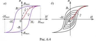
1.21. Self-induction. Magnetic field energy
Self-induction is an important special case of electromagnetic induction, when a changing magnetic flux, causing an induced emf, is created by a current in the circuit itself. If the current in the circuit under consideration changes for some reason, then the magnetic field of this current also changes, and, consequently, the own magnetic flux penetrating the circuit. A self-inductive emf arises in the circuit, which, according to Lenz’s rule, prevents a change in the current in the circuit.
The intrinsic magnetic flux Φ penetrating a circuit or coil with current is proportional to the current strength I:
| Φ = LI. |
The proportionality coefficient L in this formula is called the self-inductance coefficient or the inductance of the coil. The SI unit of inductance is called the henry (H). The inductance of a circuit or coil is 1 H if, with a direct current of 1 A, the self-flux is 1 Wb:
| 1 Gn = 1 Wb / 1 A. |
As an example, let's calculate the inductance of a long solenoid having N turns, cross-sectional area S and length l. The magnetic field of the solenoid is determined by the formula (see § 1.17)
| B = μ0 I n, |
where I is the current in the solenoid, n = N / e is the number of turns per unit length of the solenoid.
The magnetic flux penetrating all N turns of the solenoid is equal to
| Φ = BSN = μ0 n2 S l I. |
Therefore, the inductance of the solenoid is equal to
| L = μ0 n2 S l = μ0 n2 V, |
where V = Sl is the volume of the solenoid in which the magnetic field is concentrated. The result obtained does not take into account edge effects, so it is approximately valid only for sufficiently long coils. If the solenoid is filled with a substance with magnetic permeability μ, then at a given current I the magnetic field induction increases in magnitude by μ times (see § 1.17); therefore, the inductance of the core coil also increases by μ times:
| Lμ = μ L = μ0 μ n2 V. |
The self-induction emf arising in a coil with a constant inductance value, according to Faraday’s law, is equal to
The self-induction emf is directly proportional to the inductance of the coil and the rate of change of current in it.
A magnetic field has energy. Just as there is a reserve of electrical energy in a charged capacitor, there is a reserve of magnetic energy in the coil through which current flows. If you connect an electric lamp parallel to a coil with high inductance in a direct current electrical circuit, then when the key is opened, a short-term flash of the lamp is observed (Fig. 1.21.1). The current in the circuit arises under the influence of self-induction emf. The source of energy released in the electrical circuit is the magnetic field of the coil.
| Figure 1.21.1. Magnetic energy of the coil. When the key K is opened, the lamp flashes brightly |
From the law of conservation of energy it follows that all the energy stored in the coil will be released in the form of Joule heat. If we denote the total resistance of the circuit by R, then during the time Δt the amount of heat ΔQ = I2 R Δt will be released.
The current in the circuit is
The expression for ΔQ can be written as
| ΔQ = –LI ΔI = –Φ (I) ΔI. |
In this expression ΔI < 0; the current in the circuit gradually decreases from the initial value I0 to zero. The total amount of heat released in the circuit can be obtained by performing an integration operation in the range from I0 to 0. This gives
This formula can be obtained graphically by plotting the dependence of the magnetic flux Φ (I) on the current I (Fig. 1.21.2). The total amount of heat released, equal to the initial energy reserve of the magnetic field, is determined by the area shown in Fig. 1.21.2 triangles.
| Figure 1.21.2. Calculation of magnetic field energy |
Thus, the energy Wm of the magnetic field of a coil with inductance L, created by current I, is equal to
Let us apply the resulting expression for the coil energy to a long solenoid with a magnetic core. Using the above formulas for the self-induction coefficient Lμ of the solenoid and for the magnetic field B created by the current I, one can obtain:
where V is the volume of the solenoid. This expression shows that magnetic energy is not localized in the turns of the coil through which current flows, but is distributed throughout the entire volume in which the magnetic field is created. Physical quantity
equal to the magnetic field energy per unit volume is called the volumetric magnetic energy density. J. Maxwell showed that the expression for the volumetric magnetic energy density, derived here for the case of a long solenoid, is valid for any magnetic fields.
Basic formulas of the section “Electromagnetic induction”
Algorithm for solving problems on the topic “Electromagnetic induction”:
1. Carefully read the conditions of the problem. Establish the reasons for the change in the magnetic flux penetrating the circuit.
2. Write down the formula:
- law of electromagnetic induction;
- induced emf in a moving conductor, if the problem considers a progressively moving conductor; If the problem considers an electrical circuit containing a current source and an induced emf arising in one of the sections, caused by the movement of a conductor in a magnetic field, then you first need to determine the magnitude and direction of the induced emf. After this, the problem is solved by analogy with problems for calculating a direct current circuit with several sources.
3. Write down an expression for the change in magnetic flux and substitute it into the formula for the law of electromagnetic induction.
4. Write down all additional conditions mathematically (most often these are the formulas of Ohm’s law for a complete circuit, Ampere force or Lorentz force, formulas of kinematics and dynamics).
5. Solve the resulting system of equations for the desired value.
6. Check the solution.
The phenomenon of electromagnetic induction
Electromagnetic induction is the phenomenon of the occurrence of current in a closed conductive circuit when the magnetic flux passing through it changes.
The phenomenon of electromagnetic induction was discovered by M. Faraday.
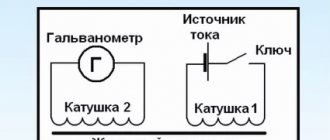
Faraday's experiments
- Two coils were wound on one non-conducting base: the turns of the first coil were located between the turns of the second. The turns of one coil were closed to a galvanometer, and the second was connected to a current source. When the key was closed and current flowed through the second coil, a current pulse arose in the first. When the switch was opened, a current pulse was also observed, but the current through the galvanometer flowed in the opposite direction.
- The first coil was connected to a current source, the second, connected to a galvanometer, moved relative to it. As the coil approached or moved away, the current was recorded.
- The coil is closed to the galvanometer, and the magnet moves - moves in (extends) - relative to the coil.
Experiments have shown that induced current occurs only when the magnetic induction lines change. The direction of the current will be different when the number of lines increases and when they decrease.
The strength of the induction current depends on the rate of change of the magnetic flux. The field itself may change, or the circuit may move in a non-uniform magnetic field.
Explanations of the occurrence of induction current
Current in a circuit can exist when external forces act on free charges. The work done by these forces to move a single positive charge along a closed loop is equal to the emf. This means that when the number of magnetic lines through the surface limited by the contour changes, an emf appears in it, which is called the induced emf.
Electrons in a stationary conductor can only be driven by an electric field. This electric field is generated by a time-varying magnetic field. It is called an eddy electric field . The concept of a vortex electric field was introduced into physics by the great English physicist J. Maxwell in 1861.
Properties of the vortex electric field:
- source – alternating magnetic field;
- detected by the effect on the charge;
- is not potential;
- the field lines are closed.
The work of this field when moving a single positive charge along a closed circuit is equal to the induced emf in a stationary conductor.
Law of Electromagnetic Induction
The law of electromagnetic induction (Faraday's law) sounds like this:
The induced emf in a closed loop is equal and opposite in sign to the rate of change of the magnetic flux through the surface bounded by the loop.
Mathematically it can be described by the formula:
| Faraday's law Ɛi — induced emf [V] ΔФ/Δt — rate of change of magnetic flux [Wb/s] |
The “–” sign in the formula allows you to take into account the direction of the induction current. The induced current in a closed circuit is always directed so that the magnetic flux of the field created by this current through the surface bounded by the circuit would reduce those changes in the field that caused the appearance of the induced current.
If the circuit consists of N turns (that is, it is a coil), then the induced emf will be calculated as follows.
| Faraday's law for a circuit of N turns Ɛi — induced emf [V] ΔФ/Δt — rate of change of magnetic flux [Wb/s] N - number of turns [-] |
The strength of the induction current in a closed conductive circuit with resistance R:
| Ohm's law for a conductive circuit Ɛi — induced emf [V] I - induction current strength [A] R - circuit resistance [Ohm] |
If a conductor of length l moves with speed v in a constant uniform magnetic field with induction B the emf of electromagnetic induction is equal to:
| Induction emf for a moving conductor Ɛi — induced emf [V] B—magnetic induction [T] v—conductor speed [m/s] l - conductor length [m] |
The occurrence of induced emf in a conductor moving in a magnetic field is explained by the action of the Lorentz force on free charges in moving conductors. The Lorentz force plays the role of an external force in this case.
A conductor moving in a magnetic field through which an induced current flows experiences magnetic braking. The total work done by the Lorentz force is zero.
The amount of heat in the circuit is released either due to the work of an external force, which maintains the speed of the conductor unchanged, or due to a decrease in the kinetic energy of the conductor.
A change in the magnetic flux penetrating a closed circuit can occur for two reasons:
- due to movement of the circuit or its parts in a time-constant magnetic field. This is the case when conductors, and with them free charge carriers, move in a magnetic field
- due to changes in time of the magnetic field with a stationary circuit. In this case, the occurrence of induced emf can no longer be explained by the action of the Lorentz force. The phenomenon of electromagnetic induction in stationary conductors, which occurs when the surrounding magnetic field changes, is also described by Faraday's formula
Thus, the phenomena of induction in moving and stationary conductors proceed in the same way, but the physical reason for the occurrence of induction current turns out to be different in these two cases:
- in the case of moving conductors, the induced emf is due to the Lorentz force
- in the case of stationary conductors, the induced emf is a consequence of the action on free charges of the vortex electric field that occurs when the magnetic field changes.
Self-induction. Inductance
“Science is often confused with knowledge.
This is a deep misunderstanding.
Science is not only knowledge, but also consciousness,
those. ability to use knowledge"
IN. Klyuchevsky
The phenomenon of electromagnetic induction is that in a closed circuit, when the magnetic flux changes, an electric current arises in it, which is called induction
.
Law of Electromagnetic Induction
states: the average value of the induced emf in a conducting circuit is proportional to the rate of change of the magnetic flux through the surface limited by the circuit.
The minus sign in the mathematical notation of the law takes into account Lenz’s rule
, according to which electromagnetic induction creates an induced current in a circuit in such a direction that the magnetic field it creates prevents a change in the magnetic flux that causes this current.
Electromagnetic induction manifests itself in all cases of change in magnetic flux through a surface bounded by a contour. Faraday's contemporary, American physicist Joseph Henry, independently of his English colleague, discovered some of the electromagnetic effects. In 1829, Henry discovered that induced emf occurs in a stationary circuit and in the absence of a change in the external magnetic field
.
It turned out that a changing electric current passing in a circuit creates a changing magnetic flux
.
This phenomenon has been called the phenomenon of self-induction
.
What's remarkable is that both Henry and Faraday were working on the same problem. And they came to the same conclusions regarding both the phenomenon of electromagnetic induction and the phenomenon of self-induction. At the same time, Henry made his discoveries several years earlier than Michael Faraday. But Henry was irresponsibly slow in publishing the results of his experiments, and Faraday was the first to report his success. Finally, priority was given to the discovery of electromagnetic induction by Faraday, and Henry was given the discovery of the phenomenon of self-induction, which he described in the same article as the phenomenon of induction, in 1832.
Self-induction is an important special case of the phenomenon of electromagnetic induction
.
If the electric current in a closed conducting circuit changes for some reason, then the magnetic field of this current also changes (i.e., the magnetic field induction is proportional to the current strength in the circuit
).
But when the induction of the magnetic field created by the current passing in the circuit changes, the magnetic flux also changes (i.e. the magnetic flux will be proportional to the magnetic field induction
).
Therefore, the magnetic flux through the surface bounded by the loop is proportional to the current in the loop
.
The proportionality coefficient between magnetic flux and current strength Thomson (later Lord Kelvin) in 1853 proposed to call the “ self-induction coefficient”
».
The self-inductance coefficient, which is often called simply the loop inductance, is denoted by L
.
Inductance in SI is measured in H (henry)
.
[L
] = [Gn]
This unit is determined based on the formula
The inductance of the circuit is equal to 1 H if, with a direct current in the circuit of 1 A, the magnetic flux through the surface limited by this circuit is equal to 1 Wb.
Inductance depends on the size and shape of the circuit, as well as on the magnetic properties of the environment in which the circuit is located
.
For example, if we take a single-layer solenoid, then its inductance will be determined by the formula
where is the number of turns per unit length of the solenoid,
S
- surface area limited by the coil,
l
— solenoid length,
m
— magnetic permeability of the medium.
From the formula for magnetic flux it follows that it can be changed by changing the current strength in the circuit, or its inductance, or both at the same time.
According to the law of electromagnetic induction, a changing magnetic flux creates an EMF in the circuit. The occurrence of induced emf in a circuit, which is caused by a change in the magnetic field of the current passing in the same circuit, is called the phenomenon of self-induction
, and the emerging emf is the electromotive force of self-induction or
self-induction emf
.
Self-inductive emf is denoted by the Greek letter x Si
. The self-induction emf is measured in V (volts).
[ x Si
] = [V]
According to the law of electromagnetic induction, the average value of the self-induction EMF arising in the circuit is directly proportional to the inductance of the circuit and the rate of change of current in the circuit (taking into account that the inductance of the circuit remains constant).
From this formula it follows that inductance
is a physical quantity numerically equal to the self-inductive emf that occurs in the circuit when the current changes by 1 A in 1 s.
Using this expression, we can give a second definition of the unit of inductance
: an element of an electrical circuit has an inductance of 1 H if, with a uniform change in the current strength in the circuit by 1 A in 1 s, a self-inductive emf of 1 V arises in it.
Since the circuit is closed, the self-inductive emf creates a self-induction current in it, the strength of which is determined by Ohm’s law
where R
— circuit resistance.
Minus sign
in the formula for self-induction emf,
it takes into account Lenz's rule
, according to which
the self-induction current is always directed so that it counteracts the change in the current created by the source
. If the main current increases, then the self-induction current is directed opposite the source current; if it decreases, then the direction of the source current and the self-induction current coincide.
How to observe the phenomenon of self-induction?
To do this, we will assemble an electrical circuit consisting of a coil with high inductance, a resistor with electrical resistance equal to the resistance of the coil winding, two identical light bulbs, a key and a direct current source.
When the circuit is closed, light bulb 2 begins to glow almost immediately, and light bulb 1 with a noticeable delay. This happens due to the fact that as the current strength I
1, created by the source, in the area formed by the coil and light bulb 1, the self-induction EMF in the coil has such a polarity that the self-induction current it creates is directed towards the source current. As a result, the increase in current strength in this section of the circuit slows down, and the current strength does not immediately reach its maximum value.
The phenomenon of self-induction can also be observed when the circuit is opened
. To do this, we will assemble a circuit consisting of a coil with a large number of turns wound on an iron core, to the terminals of which a light bulb with a high electrical resistance is connected in parallel compared to the resistance of the coil winding. As a current source, let's take a source with a small EMF.
When the key is opened, the part of the circuit consisting of a coil and a light bulb already connected in series remains closed. While the key is closed, the light bulb will glow dimly, since the ratio of the currents passing through the light bulb and the coil is inverse to the ratio of their resistances.
However, when you open the key, you can see that the light flashes brightly.
Why is this happening?
The thing is that when the circuit is opened, the current strength in the coil decreases, which leads to the appearance of a self-induction emf. The self-induction current arising in the circuit, according to Lenz's rule, coincides in direction with the coil current, preventing it from sharply reducing the current strength. This is what makes the light bulb flash.
Note that the phenomenon of self-induction occurs in any case of a change in current strength in a circuit containing inductance, or a change in the inductance itself.
In general, the phenomenon of self-induction is similar to the phenomenon of inertia in mechanics
.
It is known that a car cannot instantly acquire a certain speed, just as it cannot stop instantly, no matter how great the braking force is.
In the same way, due to self-induction when the circuit is closed, the current strength does not immediately reach its maximum value, but increases gradually. When the source is turned off, the current does not stop immediately - self-induction will maintain it for some time, even despite the high resistance of the circuit.
Exercises.
Task:
Over a period of time of 9.5 ms, the current in the inductor gradually increased from 1.6 A to 2.4 A. At the same time, a self-induction emf of –14 V arose in the coil. Determine its own magnetic flux at the end of the process of increasing current.
Main conclusions:
– The phenomenon of the occurrence of induced emf in an electrical circuit as a result of a change in current strength in the same circuit is called the phenomenon
of self-induction
.
– Self-induced emf
is equal to the product of the inductance of the circuit and the rate of change of current in it.
– Inductance
is a physical quantity numerically equal to the self-inductive emf that occurs in the circuit when the current changes by 1 A in 1 s.
– The SI unit of inductance is Hn (henry)
.
– Loop inductance is 1 H
, if with a current strength in the circuit of 1 A, the magnetic flux through the surface limited by this circuit is equal to 1 Wb.
Lenz's rule
To determine the direction of the induced current, you need to use Lenz's rule.
Academically, this rule is as follows: the induced current excited in a closed loop when the magnetic flux changes is always directed in such a way that the magnetic field it creates prevents the change in the magnetic flux causing the induced current.
Let's try a little simpler: the coil in this case is a dissatisfied granny. They take away her magnetic flux - she is unhappy and creates a magnetic field, which this magnetic flux wants to take back.
They give her a magnetic flux, take it, they say, use it, and she’s like, “Why did I give up your magnetic flux!” and creates a magnetic field, which expels this magnetic flux.
Magnetic flux
An electromagnetic field appears around a conductor carrying electric current, but in parallel, the opposite phenomenon also occurs - electromagnetic induction. Let's consider magnetic flux using an example: if a frame made of a conductor is placed in an electric field with induction and moved from top to bottom along magnetic lines of force or left and right perpendicular to them, then the magnetic flux passing through the frame will be a constant value.
When the frame rotates around its axis, then after some time the magnetic flux will change by a certain amount. As a result, an induced emf appears in the frame and an electric current appears, which is called induction.
How to use the power of self-induction in life:
Physics is nothing without practical application. The phenomenon of self-induction is actively used in everyday life. For example, an ignition coil is involved in the operation of a carburetor engine.
The ignition coil receives a charge of 12 V. The electrical circuit is terminated using a special breaker. This creates a strong spark that ignites the fuel. The car starts moving. In modern machines, the circuit breaks automatically, but the principle of self-induction remains the same.
Self-induction is also used in the operation of network filters. It helps smooth out voltage surges and fill gaps in the current supply. As a result, it is possible to eliminate noise, ripple and unnecessary frequencies.
Self-induction of the coil is used to ignite electrodes in gas-discharge light sources. When the starter is triggered, the contacts are broken, which causes a self-induced emf to arise in the coil. The lamp begins to perform its function due to a burst of energy.
Examples of use in practice
The phenomenon of self-induction has found wide practical application. Car enthusiasts know very well what an ignition coil is. Without it, the carburetor engine will not start.
This important node works as follows:
- An on-board voltage of 12 V is supplied to the coil with high inductance.
- The electrical circuit is abruptly interrupted by a special breaker.
- The accumulated energy of self-induction is supplied through high-voltage wires to the spark plug and forms a powerful spark at its electrodes.
- A spark discharge ignites the fuel mixture, driving the piston.
In modern cars, the circuit is broken by electronics, but the essence does not change - self-induction energy is still used to form a spark.
We have already mentioned network filters that use the phenomenon of self-induction. The RL chain reacts to any change in parameters. As it increases, it delays peak surges in time and fills gaps with its own eddy currents. Thus, the voltage in the electrical circuits is smoothed out.
In power supplies for electronic equipment, the following is removed in the same way:
- noises:
- pulsations;
- unwanted frequencies.
Self-induction of chokes is used in fluorescent lamps to ignite electrodes. After the starter is triggered, the contacts break, resulting in a self-inductive emf being induced in the inductor. The choke energy ignites an arc on the electrodes, and the fluorescent lamp begins to glow.
The examples listed demonstrate the useful application of self-induction. However, as always happens, induced emf can cause harm. When disconnecting the contacts of switches whose load is circuits with high inductance, arc discharges are possible. They destroy contacts, slow down the protection time, etc. In order to reduce the risk from the negative effects of self-induction, circuit breakers are equipped with arc suppression chambers.
In such cases, it is necessary to take measures to neutralize the energy of the self-induction EMF. An even greater need for dissipating self-induction energy arises in semiconductor switches that are sensitive to breakdowns.
In industry and energy, self-induction is a serious problem. When disconnecting loaded lines, the self-induction emf can reach life-threatening values. This requires additional costs for taking precautions. In particular, it is necessary to install devices on the lines that prevent the lightning-fast opening of the circuit.
What is important to remember about inductance
As already noted, the inductance of the circuit can change depending on its geometry, coverage, and magnetic characteristics of the environment. These rules also apply to the throttle. Its inductance can vary depending on the diameter and intensity of the winding. The inductance value will also increase when using a ferromagnetic core.
The degree of inductance will vary according to how strongly the transmitter, the role of which is played by the spirals, resists the electrical impulse. With high inductance and a quick stop of its circuit, a strong surge of EMF will occur.
Inductance is expressed using the Henry unit. 1H corresponds to an emf of 1V at a rate of current change of 1A per second.
The inductance value helps determine how much energy is released due to the magnetic field during self-induction. The energy can be calculated using the formulation Wm = LI2 / 2.
Self-induction and inertia
The phenomenon of self-induction is easier to understand by drawing an analogy with inertia in mechanics. Inertia leads to the fact that under the influence of force a body does not instantly acquire speed, but gradually. The body cannot be instantly slowed down, no matter how great the braking force. In the same way, due to self-induction, when the circuit is closed, the current strength does not immediately acquire a certain value, but increases gradually. By turning off the source, we do not stop the current immediately. Self-induction maintains it for some time, despite the resistance of the circuit.
To increase the speed of a body, according to the laws of mechanics, work must be done. When braking, the body itself does work. In the same way, to create a current, work must be done against the vortex electric field, and when the current disappears, this field does positive work.
What is an inductor
What do you mean by the word “reel”? Well... this is probably some kind of “fig” on which threads, fishing line, rope, whatever! An inductor coil is exactly the same thing, but instead of a thread, fishing line or anything else, ordinary copper wire in insulation is wound there.
The insulation can be made of clear varnish, PVC insulation, or even fabric. The trick here is that although the wires in the inductor are very close to each other, they are still isolated from each other. If you wind inductor coils with your own hands, do not under any circumstances even think about using ordinary bare copper wire!
Series and parallel connection of inductors
When inductors are connected in series, their total inductance will be equal to the sum of the inductances.
And with a parallel connection we get this:
When connecting inductors, the rule must be followed so that they are spatially separated on the board. This is because if they are close to each other, their magnetic fields will influence each other and therefore the readings of the inductances will be incorrect. Do not place two or more toroidal coils on one iron axis. This may result in incorrect total inductance readings.
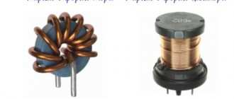
Types of Inductors
Inductors are divided mainly into two classes: with a magnetic and non-magnetic core. Below in the photo is a coil with a non-magnetic core.
But where is her core? Air is a non-magnetic core :-). Such coils can also be wound on some cylindrical paper tube. Inductance coils with a non-magnetic core are used when the inductance does not exceed 5 millihenry.
And here are the inductors with a core:
Cores made of ferrite and iron plates are mainly used. The cores increase the inductance of the coils significantly. Cores in the form of a ring (toroidal) allow you to obtain higher inductance than just cylinder cores.
For medium inductance coils, ferrite cores are used:
Coils with high inductance are made like a transformer with an iron core, but with one winding, unlike a transformer.
induced emf
Let us understand in detail what the concept of induced emf is. When a conductor is placed in a magnetic field and moves with the intersection of field lines, an electromotive force called induced emf appears in the conductor. It also occurs if the conductor remains stationary, and the magnetic field moves and intersects the conductor with lines of force.
When the conductor where the EMF occurs is closed to the external circuit, due to the presence of this EMF, an induced current begins to flow through the circuit. Electromagnetic induction involves the phenomenon of inducing an EMF in a conductor at the moment it is crossed by magnetic field lines.
Electromagnetic induction is the reverse process of transforming mechanical energy into electric current. This concept and its laws are widely used in electrical engineering; most electric machines are based on this phenomenon.
Definition
Self-induction is the appearance in a conductor of an electromotive force (EMF) directed in the opposite direction relative to the voltage of the power source when current flows. Moreover, it occurs at the moment when the current strength in the circuit changes. A changing electric current generates a changing magnetic field, which in turn induces an emf in the conductor.
This is similar to the formulation of Faraday's law of electromagnetic induction, which states:
When a magnetic flux passes through a conductor, an emf occurs in the latter. It is proportional to the rate of change of magnetic flux (mathematical derivative with respect to time).
That is:
E=dФ/dt,
Where E is the self-inductive emf, measured in volts, F is the magnetic flux, the unit of measurement is Wb (weber, also equal to V/s)
EMF in everyday life and units of measurement
Other examples are found in the practical life of any ordinary person. This category includes such familiar things as small batteries, as well as other miniature batteries. In this case, the working EMF is formed due to chemical processes occurring inside constant voltage sources. When it occurs at the terminals (poles) of the battery due to internal changes, the element is completely ready for operation. Over time, the EMF decreases slightly, and the internal resistance increases noticeably.
As a result, if you measure the voltage on a AA battery that is not connected to anything, you see the normal 1.5V (or so), but when a load is connected to the battery, let’s say you installed it in some device, it does not work. Why? Because if we assume that the voltmeter’s internal resistance is many times higher than the internal resistance of the battery, then you measured its EMF. When the battery began to supply current to the load at its terminals, it became not 1.5V, but, say, 1.2V - the device did not have enough voltage or current for normal operation.
Calculation of EMF.
It was precisely these 0.3 V that dropped on the internal resistance of the galvanic element. If the battery is very old and its electrodes are destroyed, then there may be no electromotive force or voltage at all at the battery terminals - i.e. zero. A very small electromotive force is induced within the receiver antenna, which is then amplified by special cascades, and we receive our television, radio and even Wi-Fi signal.
Self-induction and transient processes in electrical circuits
The inductance of an electric stove or incandescent light bulb is very small, and the current in these electrical appliances, when turned on and off, appears or disappears almost instantly. The inductance of the electric motor is high, and it “goes into operation” within a few minutes.
If you turn off the current in a large electromagnet with a large induction value, allowing a high rate of decrease in the current, then a spark flashes between the contacts of the switch, and in the case of a large current, a voltaic arc may light up. This is a dangerous phenomenon, therefore, in circuits with high inductance, the current is reduced gradually using a rheostat (an element with variable electrical resistance).
Safely shutting off power is a serious issue. All switches are subject to “shock loads” that arise due to the self-inductive emf when the current is turned off, and the switches “spark.” For each type of switch, the maximum current value that can be switched is indicated. If the current exceeds the permissible value, an electric arc may flash in the switch.
In hazardous industries, coal mines, and petroleum product storage facilities, simple sparking of switches is unacceptable. Explosion-proof switches are used here, reliably protected by a sealed plastic housing. The price of such switches is tens of times higher than ordinary ones - this is a necessary payment for safety.