For other uses, see Solenoid (disambiguation).
| This article raises many issues. Please help | This article may be too technical for most readers to understand . |
| This article need additional quotes for verification . |
(Learn how and when to remove this message template)
Solenoid Illustration The magnetic field is created by a seven-circuit solenoid (cutaway view) described using field lines
A solenoid
(/ˈsoʊləpɔɪd/,[1] from Greek σωληνοειδής
sōlēnoeidḗs
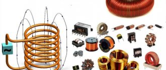
, "tubular"[2]) is a type of electromagnet whose purpose is to create a controlled magnetic field through a coil wound in a tightly packed helix.
The coil can be positioned to create a uniform magnetic field throughout a volume of space when an electric current passes through it. Period, the term solenoid
was coined in 1823 by André-Marie Ampère to refer to a helical coil.[3]
When studying electromagnetism, a solenoid is a coil whose length is significantly greater than its diameter.[4] The solenoid coil does not necessarily have to rotate about a straight axis; For example, William Sturgeon's 1824 electromagnet consisted of a solenoid bent into a horseshoe shape.
In engineering, the term can also refer to a variety of transducer devices that convert energy into linear motion.[5] Simply put, a solenoid converts electrical energy into mechanical work. The term is also often used to refer to a solenoid valve, an integrated device containing an electromechanical solenoid that operates either a pneumatic or hydraulic valve or a solenoid switch, which is a specific type of relay that internally uses an electromechanical solenoid to operate an electrical switch; such as a car starter solenoid or a linear solenoid. Solenoid bolts, a type of electromechanical locking mechanism, also exist. In electromagnetic technology, a solenoid is an actuator assembly with a sliding ferromagnetic piston inside a coil. Without power, the plunger extends part of its length beyond the coil; the supply of energy pulls the piston into the coil. Electromagnets with fixed cores are not considered solenoids.
Content
- 1 Infinite Continuous Solenoid 1.1 Inside
- 1.2 beyond
- 1.3 Quantitative description
- 6.1 Electromechanical solenoid 6.1.1 Proportional solenoid
Infinite continuous solenoid
An infinite solenoid has infinite length but finite diameter. "Continuous" means that the solenoid is formed not of discrete coils of finite width, but of many infinitely thin coils with no gaps between them; in this abstraction the solenoid is often viewed as a cylindrical sheet of conductive material.
Inside
Figure 1: Infinite solenoid with three arbitrary ampere loops labeled a
,
b
, and
c
.
Integration along path c
shows that the magnetic field inside the solenoid must be radially uniform.
The magnetic field inside an infinitely long solenoid is uniform, and its strength does not depend either on the distance from the axis or on the cross-sectional area of the solenoid.
This is the output of the magnetic flux density around the solenoid, which is long enough that edge effects can be ignored. In Figure 1 we immediately know that the flux density vector is directed towards positive z
the direction is inside the solenoid, and in negative
z
the direction is outside the solenoid. We confirm this by applying the right-hand grip rule to the field around the wire. If we wrap our right hand around a wire, with our thumb pointing in the direction of the current, the curve of our fingers will show how the field behaves. Since we are dealing with a long solenoid, all non-upward components of the magnetic field are compensated by symmetry. Outside, a similar cancellation occurs, but the field is only directed downward.
Now consider an imaginary loop c
which is located inside the solenoid.
By Ampere's Law, we know that the line integral of B
(the magnetic flux density vector) around this loop is zero, since it contains no electric currents (we can also assume that the loop the electric field passing through the loop is constant under these conditions: constant or constantly changing current through the solenoid).
We showed above that the field is directed upward inside the solenoid, so the horizontal sections of the contour c
contribute nothing to the integral. Thus, the integral of the top side 1 is equal to the integral of the back side 2. Since we can arbitrarily change the dimensions of the loop and get the same result, the only physical explanation is that the integrands are actually equal, that is, the magnetic field inside the solenoid is radially uniform. However, note that nothing prevents it from changing in the longitudinal direction, which in fact it does.
outside
A similar argument can be applied to loop a
to conclude that the field outside the solenoid is radially uniform or constant. This last result, which strictly holds only near the center of the solenoid, where the field lines are parallel to its length, is important because it shows that the flux density outside is practically zero, since the field radii outside the solenoid will tend to infinity.
An intuitive argument can also be used to show that the flux density outside the solenoid is effectively zero. Magnetic field lines only exist as loops, they cannot diverge or converge to a point like electric field lines (see Gauss's Law for magnetism). The magnetic field lines follow the longitudinal path of the solenoid inside, so they must go in the opposite direction outside the solenoid for the lines to form a loop. However, the volume outside the solenoid is much larger than the volume inside, so the density of the field lines outside is significantly reduced. Recall that the external field is constant. For the total number of field lines to be maintained, the external field must tend to zero as the length of the solenoid increases.
Of course, if the solenoid is made in the form of a coil of wire (as is often done in practice), then it emits an external field in the same way as a single wire, due to the current flowing along the entire length of the solenoid.
Quantitative description
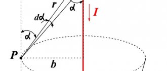
The picture shows how Ampere's Law can be applied to a solenoid.
Applying Ampere's Law bypass to a solenoid (see picture at right) gives us
B l = μ 0 N i , { displaystyle Bl = mu _ {0} NI,}
where B { displaystyle B} is the magnetic flux density, l { displaystyle l} the length of the solenoid, μ 0 { displaystyle mu_{0)} is the magnetic constant, N { displaystyle N} the number of turns, and I { displaystyle I} the electric current. From here we get
B = μ 0 N i l . { displaystyle B = mu _ {0} { frac {NI} {l)).}
This equation is valid for a solenoid in free space, which means that the permeability of the magnetic path is the same as the permeability of free space, μ0.
If the solenoid is immersed in a material with relative permeability μр, then the field increases by this amount:
B = μ 0 μ r N i l . { displaystyle B = mu _ {0} mu _ { mathrm {r}} { frac {NI} {l}}.}
In most solenoids, the solenoid is not immersed in a material with higher permeability, but rather some of the space around the solenoid is material with higher permeability, and some is just air (which behaves like free space). In this scenario, the full effect of the high permeability material is not visible, but there will be effective (or apparent) permeability. μ
eff such that 1 ≤
μ
eff ≤
μ
r.
Incorporating a ferromagnetic core, such as an iron, increases the magnitude of the magnetic flux density in the solenoid and increases the effective permeability of the magnetic path. This is expressed by the formula
B = μ 0 μ e f f N i l = μ N i l , { displaystyle B = mu _ {0} mu _ { mathrm {eff} } { frac {NI} {l)) = mu { frac {NI} {l}},}
where μ
eff is the effective or apparent permeability of the core. Effective permeability is a function of the geometric properties of the core and its relative permeability. The terms relative permeability (a property of the material only) and effective permeability (a property of the entire structure) are often confused; they can differ by many orders of magnitude.
For an open magnetic structure, the relationship between effective permeability and relative permeability is defined as follows:
μ e f f = μ r 1 + k ( μ r − 1 ) , { displaystyle mu _ { mathrm {eff} } = { frac { mu _{r} } {1 + k ( mu _{r} -1) }},}
where k
— core demagnetization coefficient.[6]
Magnetic field created by the coil
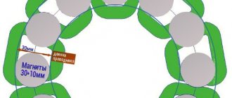
When an electric current passes through the windings of the coils, it behaves like an electromagnet and the plunger, which is located inside the coil, is attracted to the center of the coil by the magnetic flux inside the body of the coils, which in turn is compressed by a small spring attached to one end of the plunger. The force and speed of movement of the plungers are determined by the strength of the magnetic flux generated inside the coil.
When the supply current is turned off (de-energized), the electromagnetic field previously created by the coil is destroyed, and the energy stored in the compressed spring forces the piston to return to its original resting position. This back and forth movement of the plunger is known as the "stroke" of the solenoids, in other words, the maximum distance the plunger can travel in the "in" or "out" direction, for example 0-30mm.
This type of solenoid is usually called a linear solenoid due to the linear directional movement and plunger action. Linear solenoids are available in two basic configurations, called "pull type" since it pulls the connected load toward itself when they are energized, and "push type" which act in the opposite direction, pushing it away from it when power is applied. Both push-pull and push-pull types typically have the same design, with differences in the location of the return spring and the design of the plunger.
Magnetic field created inside.
End continuous solenoid
Magnetic field line and density produced by a solenoid with surface current density
A finite solenoid is a solenoid of finite length. Continuous means that the solenoid is not formed by individual coils, but by a sheet of conductive material. We assume that the current is uniformly distributed over the surface of the solenoid, with the surface current density K
;
into cylindrical coordinates: K → = i l ϕ ^ .
{ displaystyle { vec {K}} = { frac {I} {l}} { hat { phi}}.} The magnetic field can be found using the vector potential, which for a finite solenoid of radius r
and the length
l
in cylindrical coordinates ( ρ , ϕ , z ) { displaystyle ( rho, phi, z)} is [7]
A ϕ = μ 0 i 4 π 1 l r ρ [ ζ k ( k 2 + h 2 − h 2 k 2 hour 2 k 2 K ( k 2 ) − 1 k 2 E ( k 2 ) + hour 2 − 1 hour 2 Π ( hour 2 , k 2 ) ) ] ζ − ζ + , { displaystyle A _ { phi } = { frac { mu _ {0} I} {4 pi}} { frac {1} {l}} { sqrt { frac {R} { rho} }} left [ zeta k left ({ frac {k^{2 } + h ^ {2} -h ^ {2} k ^ {2}} {h ^ {2} k ^ {2}}) } K (k ^ {2}) — { frac {1} {k ^ {2}}} E (k^{2}) + { frac {h^{2} -1} {h^{2}}} Pi (h^{2}, k^{2}) right) right ] _ { zeta _ {-}} ^ { zeta _ {+}},}
where
ζ ± = z ± l 2 , { displaystyle zeta _ { pm} = z pm { frac {l} {2}},} h 2 = 4 r ρ ( r + ρ ) 2 , { displaystyle h^{2} = { frac {4R rho} {(R + rho)^{2}}},} k 2 = 4 R ρ ( R + ρ ) 2 + ζ 2 , { Displaystyle k^{2} = { frac {4R rho} {(R + rho)^{2} + zeta ^{2))},} K ( m ) = ∫ 0 π / 2 1 1 − m sin 2 θ d θ , { Displaystyle K ( m ) = int _ {0} ^ { pi / 2} { frac {1} { sqrt {1-m sin ^ {2} theta}}} d theta,} E ( m ) = ∫ 0 π / 2 1 − m sin 2 θ d θ , { displaystyle E (m) = int _ {0} ^ { pi / 2} { sqrt {1-m sin ^{2} theta)) d theta,} Π ( p , m ) = ∫ 0 π / 2 1 ( 1 − n sin 2 θ ) 1 − m sin 2 θ d θ . { displaystyle Pi (n, m) = int _ {0} ^ { pi / 2} { frac {1} {(1-n sin ^{2} theta) { sqrt {1- m sin ^{2} theta} }}} d theta.}
Here, K ( m ) { Displaystyle K ( m ) } , E ( m ) { Displaystyle E ( m ) } , and Π ( p , m ) { Displaystyle Pi ( n , m ) } are complete elliptic integrals of the first, second and third kind.
By using
B → = ∇ × A → , { displaystyle { vec {B)) = nabla times { vec {A)),}
The magnetic flux density is obtained as[8][9][10]
B ρ = μ 0 i 4 π 2 l r ρ [ k 2 − 2 k K ( k 2 ) + 2 k E ( k 2 ) ] ζ − ζ + , { displaystyle B _ { rho } = { frac { mu _ {0} I} {4 pi}} { frac {2} {l}} { sqrt { frac {R} { rho} }} left [{ frac {k^{2} -2} {k}} K ( k ^ {2}) + { frac {2} {k}} E (k ^ {2}) right ] _ { zeta _ {-}} ^ { zeta _ {+}},} B z = μ 0 i 4 π 1 l 1 r ρ [ ζ k ( K ( k 2 ) + r − ρ r + ρ Π ( hour 2 , k 2 ) ) ] ζ − ζ + . { displaystyle B_{z} = { frac { mu _{0} I} {4 pi)) { frac {1} {l}} { frac {1} { sqrt {R rho} }} left [ zeta k left ( K (k^{2}) + { frac {R- rho} {R + rho}} Pi (h^{2}, k^{2}) right) right] _ { zeta _ {-}} ^ { zeta_{+}}.}
On the axis of symmetry, the radial component vanishes, and the axial component of the field is equal to
B z = μ 0 N i 2 ( l / 2 − z l r 2 + ( l / 2 − z ) 2 + l / 2 + z l r 2 + ( l / 2 + z ) 2 ) { displaystyle B_ { z } = { frac { mu _ {0} NI} {2}} { Biggl (} { frac {l/2-z} {l { sqrt {R^{2}) + (l/2-z) ^ { 2}}}}} + { frac {l / 2 + z} {l { sqrt {R^{2} + (l / 2 + z)^{2}) }}}} { Biggr)}} .
Inside the solenoid, away from the ends ( | z | ≪ l / 2 − R { displaystyle | z | ll l / 2-R} ), this tends to a constant value B = μ 0 N i / l { displaystyle B = mu_{ 0} NI / l} .
Solenoid Duty Cycle
Another more practical way of reducing the heat generated by the solenoid coil is to use "intermittent duty cycle". Intermittent duty cycle means that the coil is switched ON and OFF repeatedly at a suitable frequency to activate the plunger mechanism but prevent it from de-energizing during the OFF period. Intermittent switching of the duty cycle is a very effective way of reducing the total power consumed by the coil.
The duty cycle (% ED) of a solenoid is the portion of the "ON" time when the solenoid is energized, and is the ratio of the "ON" time to the total "ON" and "OFF" times for one complete cycle of operation. In other words, the cycle time is equal to the on time plus the off time. The duty cycle is expressed as a percentage, for example:
It will be interesting➡ What is an inductor and why is it sometimes called a choke
Then if the solenoid is on or on for 30 seconds and then off for 90 seconds before turning on again, one full cycle, the total on/off cycle time will be 120 seconds, (30 + 90) so the duty cycle of the solenoids will be calculated as 30/120 sec or 25%. This means that you can determine the maximum on time of the solenoids if you know the duty cycle and off time values.
For example, the off time is 15 seconds, the duty cycle is 40%, so the on time is 10 seconds. A solenoid with a 100% duty cycle rating means it has a constant voltage rating and can therefore be left on or constantly on without overheating or damage. In this lesson on solenoids, we looked at both the linear solenoid and the rotary solenoid as an electromechanical actuator that can be used as an output device to control a physical process. In the next lesson we will continue to look at output devices called actuators and the device that again converts the electrical signal into a corresponding rotational motion using electromagnetism. The type of output device we will look at in the next lesson is the DC motor.
Material on the topic: What is a time relay.
Solenoid in package
Finite Intermittent Solenoid Evaluation
In the case where the radius is much greater than the length of the solenoid, the magnetic flux density through the center of the solenoid (in z
direction parallel to the length of the solenoid, where the coil is centered at
z
= 0) can be estimated as the magnetic induction of a single circular conducting loop:
B z = μ 0 I N r 2 2 ( r 2 + z 2 ) 3 2 { displaystyle B_{z} = { frac { mu _ {0} INR ^ {2}} {2 (R ^ {2} + z ^ {2}) ^ { frac {3} {2}} }}}
For cases where the radius is small in comparison with length, this estimate can be further refined by summing it over N
number of turns/turns of wire at different positions along
z
.
Examples of non-standard solenoids (a) dilution solenoid, (b) variable pitch solenoid, (c) non-cylindrical solenoid
Indirect acting solenoids
This type of solenoid is more complex and will take more time to explain the mechanism of its operation. Simply put, an indirect acting solenoid consists of two valves connected into one mechanism. The main valve is a spool that works according to the principle described above, the second mechanism used is the pilot valve, which is located between the spool and the electromagnet. The control valve is a small direct-acting solenoid that activates the push of the large spool. Please note that the solenoid shown in this image is a direct acting solenoid as it acts directly on the control valve, but the entire assembly is an indirect acting solenoid.
The main difference between direct acting and indirect acting solenoids is how they interact with the mechanical parts of the marker. Direct acting solenoids work directly with the elements of the marker mechanism. Indirect acting solenoids use air flow to control the spool. The main reason for the existence of indirect acting solenoids is their incredibly low power consumption compared to direct acting solenoids. For example, if a direct acting solenoid requires 4 watts to affect a mechanism, then an indirect acting solenoid only needs 0.5 watts to effect the same effect.
Solenoid operation diagram.
Next, solenoids are divided according to the number of threads. To function, the solenoid must have at least one hole through which air enters the solenoid, one hole through which air enters the mechanism, and one hole through which air is released. But in most cases, a design is used with two holes for supplying air to the marker mechanism and two air release holes. Currently, there are mainly three main types of solenoids in use:
- Four way spool valve. This type is used in most all-electro-pneumatic markers, where air is used to move the piston back and forth. For example Ego, Angel, Shocker, Dye Matrix, etc. The incorrectly named three way valve on cockers is also an example of a four-way piston.
- Three-way spool, closed when at rest (3-way spool normally closed). This is a three-flow valve that supplies air when voltage is applied to it. When this solenoid is at rest, it does not supply any pressure, for example pVI Shocker, Invert Mini.
- Three-way spool, open when at rest (3-way spool normally open). This is a three-flow valve that supplies pressure at rest, and shuts off the air flow when voltage is applied to it, such as Ion.
The control valve in the solenoid is always three-flow, closed at rest. When voltage is applied to the solenoid, the control valve opens and supplies air in order to move the spool, which, in turn, can be either three-flow or four-flow.
Each indirect acting solenoid is divided into three segments: coil, pilot and spool. The coil is the only electromagnetic part of the entire mechanism. It consists of copper wire wrapped around a metal casing, inside which there is a metal rod, which is the opposite magnetic component of the valve. The rod is made of steel and has a spring at one end. At the opposite end of the solenoid is the spool, which is the valve and the main moving part of the solenoid. Spools are usually made of brass or aluminum depending on the manufacturer.
It will be interesting➡ What is a Hall sensor
There are also various gaskets on the spool to redirect air flow. And finally, the last part of the solenoid is the control valve, which is the “mediator” between the movement of the coil rod and the spool. The main component for a control valve is a round piston that moves the spool to the open position. The piston is a small plastic disc with a gasket around it. Behind the piston is a small actuator, a piece to hold the actuator in place, and a small plug located inside the actuator. Most of these components, like the control valve body, are made of polymers to improve sliding and sealing.
Interesting material for familiarization: what are variastors.
In conclusion of the article, what is dwell? This is the time during which voltage is applied to the solenoid (respectively, the path of the marker bolt to the forward position + the time that the bolt is in the forward position, releasing air). If you lower the dwell setting too much, you will have to compensate for the shorter time the bolt stays in the forward position by increasing the operating pressure of the marker, which will not be beneficial for your marker. A too high value of the dwell parameter will lead to excessive air consumption, battery charge and greater wear of the solenoid itself.
Two identical solenoids.
Incorrect solenoids
In the category of finite solenoids, there are those that are rarely wound with a single pitch, rarely wound with a variable pitch (variable pitch solenoids), or with a variable radius for different loops (non-cylindrical solenoids). They are called irregular solenoids. They have found application in a variety of applications, such as sparsely wound solenoids for wireless power transfer,[11][12] variable pitch solenoids for magnetic resonance imaging (MRI),[13] and non-cylindrical solenoids for other medical devices.[14]
Self-inductance and capacitance calculations cannot be done using those used for traditional solenoids, i.e. tightly wound solenoids. New methods have been proposed for calculating self-inductance[15] (codes available at [16]) and capacitance.[17] (codes available at [18])
Rotary solenoid
Most electromagnetic solenoids are linear devices, producing linear force or forward and reverse motion. However, there are also rotary solenoids that produce angular or rotational movement from a neutral position in either clockwise, counterclockwise, or both directions (bidirectional). Rotary solenoids can be used to replace small DC motors or stepper motors if the angular motion is very small and the rotation angle is the angle offset from the start to end position.
It will be interesting➡ What is a pulse relay
Typically available rotary solenoids have movements of 25, 35, 45, 60 and 90 o, as well as multiple movements to and from a specific angle, such as self-restoring in two positions or returning to zero rotation, for example, from 0 to 90- to -0 ° , self-healing in 3 positions, for example from 0 ° to +45 ° or from 0 ° to -45 °, and locking in 2 positions.
Solenoid in a metal housing.
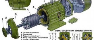
Rotating solenoids produce rotational motion when energized, de-energized, or changing the polarity of the electromagnetic field changes the position of the permanent magnet rotor. Their design consists of an electrical coil wound around a steel frame with a magnetic disk connected to an output shaft located above the coil.
When the coil is energized, the electromagnetic field generates multiple north and south poles, which repel the adjacent permanent magnetic poles of the disk, causing it to rotate at an angle determined by the mechanical design of the rotating solenoid.
Rotary solenoids are used in vending machines or gaming machines to operate valves, chamber shutters with special high speed, low energy or high force or torque adjustable positioning solenoids such as those used in dot matrix printers, typewriters, vending machines or cars.
Solenoid device diagram.
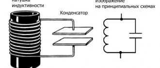
Inductance
See also: Inductance with physical symmetry
As shown above, the magnetic flux density B { displaystyle B} inside the coil is almost constant and is given by
B = μ 0 N i l , { displaystyle B = mu _ {0} { frac {NI} {l)),}
where μ
0 is the magnetic constant, N { displaystyle N} the number of turns, i { displaystyle I} current and l { displaystyle l} the length of the coil.
Ignoring end effects, the total magnetic flux through the coil is obtained by multiplying the flux density B { displaystyle B} by the cross-sectional area A { displaystyle A}: Φ = μ 0 N i A l.
{ displaystyle Phi = mu _ {0} { frac {NIA} {l}}.} Combining this with the definition of inductance
L = N Φ I , { displaystyle L = { frac {N Phi} {I)),}
the inductance of the solenoid is
L = μ 0 N 2 A l . { displaystyle L=mu_{0}{frac {N^{2}A}{l)).}
An inductance table for short solenoids with different diameter-to-length ratios was calculated by Dellinger, Whittemore and Ould.[19]
This, as well as the inductance of more complex shapes, can be obtained from Maxwell's Equation. For rigid air-core coils, the inductance depends on the coil geometry and the number of turns and is independent of current.
A similar analysis applies to a solenoid with a magnetic core, but only if the length of the coil is much greater than the product of the relative permeability of the magnetic core and the diameter. This limits simple analysis to low permeability cores or very long thin solenoids. The presence of the core can be taken into account in the above equations by replacing the magnetic constant μ0
with
μ
or
μ0μр
, where
μ
represents the permeability and
μр is
the relative permeability. Note that since the permeability of ferromagnetic materials varies with applied magnetic flux, the inductance of a ferromagnetic core coil generally varies with current.
Reduced solenoid power consumption
One of the main disadvantages of solenoids, especially a linear solenoid, is that they are "inductive devices" made from spools of wire. This means that the solenoid coil converts some of the electrical energy used to operate them into "heat" due to the resistance of the wire. In other words, when connected to a power source for a long time, they get hot, and the longer the time that power is applied to the solenoid coil, the hotter it gets. Also, as the coil heats up, its electrical resistance also changes, allowing more current to flow, increasing its temperature.
With a constant input voltage applied to the coil, the solenoid coil has no chance to cool down because the input power is always on. To reduce this self-generated heating effect, it is necessary to reduce either the amount of time the coil is energized or reduce the amount of current flowing through it. One way to draw less current is to apply a suitable high enough voltage to the electromagnetic coil to provide the necessary electromagnetic field to operate and seat the plunger, but then activate once to reduce the supply voltage to the coils to a level sufficient to keep the plunger in a "seated" state. or closed position.
Using this method, the solenoid can be connected to its voltage source indefinitely (continuous duty cycle) as the power consumed by the coil and the heat generated are greatly reduced, which can be up to 85-90% when using a suitable power resistor. However, the power consumed by the resistor will also generate a certain amount of heat, I 2 R (Ohm's law), and this must also be taken into account.
Applications
Electromechanical solenoid
A 1920 explanation of a commercial solenoid used as an electromechanical actuator.
Electromechanical solenoids consist of an electromagnetic inductive coil wound on a moving steel or iron slug (called fittings). The coil is shaped so that the armature can be moved in and out of the space at the center of the coil, changing the inductance of the coil and thereby becoming an electromagnet. The movement of an armature is used to impart mechanical force to some mechanism, such as to control a pneumatic valve. Although solenoids are typically weak over all but very short distances, they can be controlled directly by the controller circuitry and therefore have very fast response times.
The force applied to the armature is proportional to the change in inductance of the coil relative to the change in the position of the armature and the current flowing through the coil (see Faraday's Law of Induction). A force applied to an armature will always move the armature in a direction that increases the inductance of the coil.
Electromechanical solenoids are commonly found in electronic paintball guns, pinball machines, dot matrix printers, and fuel injectors. Some residential doorbells use electromechanical solenoids, whereby electrifying a coil causes an armature to strike metal partitions.[20] The electromechanical, or work solenoid, may have been first invented in England by Illitis Augustus Timmis. In 1893, he was issued patent US506282 for a solenoid having an iron rod and an outer shell to efficiently propagate magnetic flux, as is done today.
Proportional solenoid
This category of solenoids includes uniquely designed magnetic circuits that affect the analog positioning of the solenoid plunger or armature based on coil current. These solenoids, axial or rotary, use a flux-carrying geometry that both produces high starting force (torque) and has a region that quickly begins to magnetically saturate. The resulting force (torque) profile as the solenoid moves through its stroke is nearly flat or decreases from a high to a lower value. The solenoid can be useful for positioning, mid-stroke stopping, or low speed actuation; especially in a feedback control system. A single direction solenoid will operate against an opposing force, or a dual solenoid system will self-cycle. The proportional concept is described in more detail in SAE publication 860759 (1986).
Focusing the magnetic field and its accompanying flux measurement, as shown in the SAE paper, is required to produce a high starting force at the beginning of the solenoid's stroke and to maintain a level or decrease in force as the solenoid moves through its bias range. This is exactly the opposite of what happens with conventional decreasing air gap solenoids. Focusing the magnetic field toward the operating air gap initially creates high mmf (ampere-turns) and a relatively low level of magnetic flux across the air gap. This high flux product mmf x (read energy) creates a high starting force. As the plunger increases (ds), the energy of movement F ∙ ds is extracted from the energy of the air gap. Due to the increment of the plunger movement, the permeability of the air gap increases slightly, the magnetic flux increases, and the mmf in the air gap decreases slightly; all this leads to maintaining a high mmf x flow product. Due to the increased level of magnetic flux, the increase in ampere-turns drops in other parts of the iron circuit (primarily in the pole geometry) causes a decrease in air-gap ampere-turns and therefore a decrease in the potential field energy in the air-gap. Further increase in the plunger causes a constant decrease in the solenoid force, thereby creating ideal conditions for motion control, which is controlled by the current supplied to the solenoid coil. The above pole geometry with linearly varying trajectory area results in a nearly linear variation in force. An opposing spring force or two-way solenoid (two coils) controls forward and reverse motion. Feedback control improves system linearity and rigidity.
Rotary Solenoid
A rotary solenoid is an electromechanical device used to rotate the ratchet mechanism when power is applied. They were used in the 1950s to automate the rotary switch in electromechanical controls. Pressing the rotary solenoid again moves the momentary switch forward one position. Two rotary actuators on opposite ends of the rotary pushbutton switch shaft can move or reverse the position of the switch.
A rotary solenoid is similar to a linear solenoid, except that the armature core is mounted in the center of a large flat disk, with three inclined raceways fitted into the bottom of the disk. These grooves align with the raceways on the solenoid body, separated by ball bearings in the raceways.
When the solenoid is activated, the armature core is magnetically attracted to the stator pole and the disc rotates on ball bearings in the raceways as it moves towards the coil housing. When the power is turned off, a spring on the disk returns it to its original position both in rotation and in the axial direction.
The rotary solenoid was invented in 1944 by George H. Leland of Dayton, Ohio, to provide a more reliable and shock/vibration resistant release mechanism for air-dropped bombs. Previously used linear (axial) solenoids were prone to unintentional actuation. US Patent No. 2,496,880 describes the electromagnet and inclined raceways that form the basis of the invention. Leland's engineer, Earl W. Kerman, was instrumental in developing a compatible bomb release bracket that included a rotating solenoid. This type of shackle was found in the fuselage of a B-29 aircraft on display at the National Museum of the United States Air Force in Dayton, Ohio. Solenoids of this variety continue to be used in countless modern applications and are still manufactured under the original Leland "Ledex" brand, now owned by Johnson Electric.
Introduced to the market in the 1980s, the exclusively spinning solenoid with a balanced 3-blade iron-bladed rotor offered improved vibration isolation by eliminating axial movement of the rotor. This device provides proportional silent positioning as well as fast rotation for mail sorting and conveyor gates. This was followed by a permanent magnet rotor version (US Patent 5,337,030; 1994), which provided fast electrical bidirectional rotation.
Rotary voice coil
A rotary voice coil is a rotating version of a solenoid. Typically a stationary magnet is on the outside and part of the coil moves in an arc controlled by the current flowing through the coils. Rotating voice coils are widely used in devices such as the Disc Drive.[ citation needed
] The working part of a moving coil meter is also a type of rotating voice coil that rotates around the axis of the pointer, a hair spring is usually used to provide a weak, almost linear restoring force.
Pneumatic Solenoid Valve
Valve Solenoid
A pneumatic solenoid valve is a switch for directing air to any pneumatic device, usually an actuator, allowing a relatively small signal to control a large device. It is also the interface between electronic controllers and pneumatic systems.[ citation needed
]
Hydraulic solenoid valve
Hydraulic solenoid valves are generally similar to pneumatic solenoid valves, except that they regulate the flow of hydraulic fluid (oil), often at a pressure of about 3,000 psi (210 bar, 21 MPa, 21 MN/m²). Hydraulic equipment uses solenoids to control the flow of oil to hydraulic cylinders or actuators. Solenoid operated valves are often used in irrigation systems where a relatively weak solenoid opens and closes a small pilot valve, which in turn activates the main valve by applying fluid pressure to a piston or diaphragm that is mechanically connected to the main valve. also present in everyday items such as washing machines to regulate the flow and amount of water in the drum.
Transmission solenoids control the flow of fluid through an automatic transmission and are typically installed in the transmission valve body.
Car starter solenoid
Main article: Starter solenoid
In a car or truck, the starter solenoid is part of the vehicle's engine ignition system. The starter solenoid receives a large electrical current from the car battery and a small electrical current from the ignition switch. When the ignition key is turned on (that is, when the key is turned to start the vehicle), a small electrical current forces the starter solenoid to close a pair of heavy contacts, thereby transmitting a large electrical current to the starting motor. This is a type of relay.
Starter solenoids may also be built into the starter itself, often visible on the outside of the starter. If the starter solenoid is not receiving enough power from the battery, it will not be able to start the engine and may make a quick, characteristic "clicking" or "clicking" sound. This may be caused by a low or completely dead battery, a rusty or loose connection to the battery, or a broken or damaged positive (red) battery cable. Either will cause some power to be applied to the solenoid, but not enough to keep the heavy contacts closed, so the starter itself never turns and the engine doesn't start.
Description and principle of operation of the solenoid
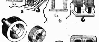
A linear solenoid operates on the same basic principle as the electromechanical relay described in the previous lesson, and just like relays, they can also be switched and controlled using transistors or MOSFETs. A linear solenoid is an electromagnetic device that converts electrical energy into a mechanical pushing or pulling force or movement. A linear solenoid basically consists of an electrical coil wound around a cylindrical tube with a ferromagnetic drive or "plunger" that can freely move or slide the "IN" and "OUT" in the coil housing. Types of solenoids are shown in the figure below.
Solenoids can be used to electrically open doors and latches, open or close valves, move and control robotic limbs and machinery, and even turn on electrical switches just by applying power to its coil. Solenoids are available in a variety of formats, with the most common types being the linear solenoid, also known as linear electromechanical actuator (LEMA) and rotary solenoid.
Solenoid and scope of application
Both types of solenoids, linear and rotary, are available in hold (constant voltage) or latch (ON-OFF pulse) form, with latch types used in energized or power-off applications. Linear solenoids can also be designed for proportional motion control, where the position of the plunger is proportional to the power input. When electric current flows through a conductor, it generates a magnetic field, and the direction of this magnetic field relative to its north and south poles is determined by the direction of current flow within the wire.
This coil of wire becomes an "electromagnet" with its own north and south poles, just like a permanent magnet. The strength of this magnetic field can be increased or decreased either by controlling the amount of current flowing through the coil or by changing the number of turns or loops the coil has. An example of an "electromagnet" is given below.
Recommendations
- The Cambridge Advanced Learner's Dictionary
gives two phonetic variants /ˈsəʊ.lə.nɔɪd/ and /ˈsoʊ.lə.nɔɪd/."Solenoid: meaning in the Cambridge English Dictionary."
dictionary.cambridge.org
. Archived from the original on January 16, 2022. Retrieved January 16, 2017. - The French term was coined in 1823 from σωλήν "channel, pipe" and the -oid (-o-ειδής) suffix. "Solenoid" in: Trésor de la langue française informatisé
.
The Greek σωληνοειδ, "trumpet shape", is first attested in Aeneas Tacticus (4th century BC). Henry George Liddell, Robert Scott, A Greek-English Lexicon
(1843).
See also "Solenoid". Online Dictionary of Etymology
. Archived from the original July 28, 2011 - Session of the Academy of Sciences
of December 22, 1823, printed in: Ampère, "Mémoire sur la théorie mathématique des phénomènes électro-Dynamiques",
Mémoires de l'Académie royale des Sciences de l'Institut de France
6 (1827), Paris , F. Didot, S. 267ff.
(and figs. 29–33). "l'assemblage de tous les circuit qui l'entourent [namely l'arc], Assemblage auquel j'ai donné le nom de electro-dynamic solenoid
, du mot grec σωληνοειδὴς, dont laignation ex prime précising ce qui a la forme d' un canal, c'est-à-dire la surface de cette forme sur laquelle se Trouvent tous les circuit” (p. 267). - or, what is the same, the diameter of the coil is assumed to be infinitely small (Ampère 1823, p. 267: “des courants électriques formants de très-petits circuit autour de cette ligne, dans des plan infiniment rapprochés qui lui soient perpendiculaires”).
- [[1]]
- Giles, David. Introduction to magnetism and magnetic materials. CRC press, page 48, 2015.
- "Archive copy" (PDF). Archived (PDF) from the original April 10, 2014. Retrieved March 28, 2013.CS1 maint: archived copy as title (site link)
- Müller, Karl Friedrich (1 May 1926). "Berechnung der Induktivität von Spulen" [Calculation of the inductance of coils]. Archiv für Elektrotechnik
(in German).
17
(3):336–353. Doi:10.1007/BF01655986. ISSN 1432-0487. S2CID 123686159. - Callaghan, Edmund E.; Maslen, Stephen H. (October 1, 1960). "Magnetic field of a finite solenoid". NASA Technical Reports
. NASA-TN-D-465 (E-900). - Caciagli, Alessio; Baars, Roel J.; Phillips, Albert P.; Kuipers, Bonny W. M. (2018). "An exact expression for the magnetic field of a finite cylinder with arbitrary uniform magnetization". Journal of Magnetism and Magnetic Materials
.
456
:423–432. doi:10.1016/j.jmmm.2018.02.003. ISSN 0304-8853. - Course, Andre; Karalis, Aristeidis; Moffatt, Robert; Joannopoulos, J.D.; Fisher, Peter; Soljacic, Marin (6 July 2007). "Wireless energy transfer using tightly coupled magnetic resonances". The science
.
317
(5834):83–86. Doi:10.1126/science.1143254. PMID 17556549. S2CID 17105396. - Zhou, Wenshen; Huang, Shao Ying (September 28, 2022). "A New Coil Design for Broadband Wireless Power Transmission". 2022 International Applied Computational Electromagnetics Society (ACES) Symposium
. - Ren, Zhi Hua; Huang, Shao Ying (August 2022). "Design of a short solenoid with uniform B1 for portable low-field magnetic resonance imaging using genetic algorithm." Proc.
26th ISMRM : 1720. - Jian, L.; Shi, Y.; Liang, J.; Liu, C.; Xu, G. (June 2013). "A Novel Targeted Magnetic Fluid Hyperthermia System Using an HTS Coil Array for Tumor Treatment." IEEE Transactions on Applied Superconductivity
.
23
(3): 4400104. doi:10.1109/TASC.2012.2230051. S2CID 44197357. - Zhou, Wenshen; Huang, Shao Ying (July 2022). "An accurate model for quickly calculating the resonant frequency of an irregular solenoid". IEEE Proceedings of Microwave Theory and Techniques
.
67
(7):2663–2673. Doi:10.1109/TMTT.2019.2915514. S2CID 182038533. - Zhou, Wenshen; Huang, Shao Ying. "An accurate model code for quickly calculating the resonant frequency of an irregular solenoid." Magazine citation required | log = (Help)
- Zhou, Wenshen; Huang, Shao Ying (October 2022). "Modeling the intrinsic capacitance of an irregular solenoid". IEEE Transactions on Electromagnetic Compatibility
: 1–9. Doi:10.1109/TEMC.2020.3031075. - Zhou, Wenshen; Huang, Shao Ying. "Precision Model Code for Determining the Intrinsic Capacitance of Non-Standard Solenoids." Magazine citation required | log = (Help)
- D. Howard Dellinger; L. E. Whittemore and R. S. Ould (1924). Radio instruments and measurements
.
NBS Circular
.
C74
. ISBN 9780849302527. Retrieved September 7, 2009. - "How to hold a doorbell." Popular Science
(March 1975). March 1975. p. 117. Archived from the original May 14, 2018. Retrieved November 29, 2022.
external reference
| Wikimedia Commons has media related to Solenoids . |
- Interactive Java Tutorial: Magnetic Field of a Solenoid, National High Magnetic Field Laboratory
- Discussion of solenoids in hyperphysics
- Basics of Solenoids for Robotics
- Rotating Voice Coil Basics
- What is a solenoid
- How does a DC solenoid work?
- [2] Macro Magnetics.pdf; Calculation of solenoid forces
| Authoritative control |
|
Simple drivers for solenoids
The easiest way to control a solenoid is to turn the current on and off. This is often done using a low side MOSFET switch and a current protection diode (picture below). In this circuit, the current is limited only by the supply voltage and the constant resistance of the solenoid.
The electromechanical performance of a simple solenoid actuator is limited. Since full voltage and current are applied 100% of the time, the pull-in current is limited by the constant power dissipation of the solenoid. The large inductance of the coil limits the rate of current rise when the solenoid is turned on.
The test measured the movement, voltage and current of a solenoid activated using a simple switch (picture below). In this case, the solenoid (15 ohm rated at 12 V) took 30 ms to turn on to drive the mechanical drive and dissipate 10 W of power.
If you are wondering about the "valley" in the current waveform, this decrease in current is due to the back EMF created by the moving solenoid core. The back EMF increases as the core accelerates until the solenoid retracts and stops.