It is often necessary to reduce the rotation speed of a motor that performs certain tasks in a mechanism. Reducing the speed of an electric motor can be achieved using homemade devices and standard-made control circuits.
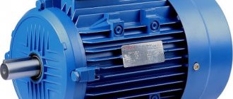
AC electric motors are often used in human activities, on metalworking machines, transport, crane mechanisms and other equipment. Motors convert alternating current energy into rotation of the shaft and components. Mainly asynchronous AC motors are used.
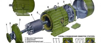
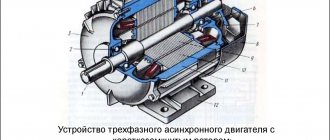
The rotor, as well as the stator of the motor, consists of coils of wire placed in a core made of special steel. The classification of electric motors follows from the method of laying the winding.
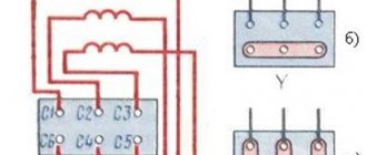
A winding of brass and copper rods is inserted into the core, and rings are installed along the edges. Such a coil of wire is called a short-circuited (SC) rotor. Small power electric motors have rods as well as discs that have been cast together. For electric motors with high torque, the parts are cast separately and then welded. The stator winding can be connected in two ways: triangle, star.
The phase rotor consists of a 3-phase rotor winding connected by slip rings and brushes to the power supply. The winding is star connected.
Calculation of the number of revolutions of an asynchronous motor
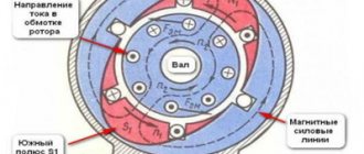
A common motor in machine tools and lifting devices is a squirrel-cage motor, so the calculation example should be taken for this type. The mains voltage is supplied to the stator winding. The windings are offset from each other by 120 degrees. The resulting electromagnetic induction field excites an electric current in the winding. The rotor begins to operate under the influence of EMC.
The main characteristic of engine operation is the number of revolutions per minute. We calculate this value:
n = 60 f/p, rpm;
where f is the network frequency, hertz, p is the number of stator poles (in pairs).
There is a plate with technical data on the motor housing. If it is not there, then you can calculate the number of revolutions of the equipment shaft yourself using other available data. The calculation is made in three ways.
- The calculation of the number of coils, which is compared with the standards for different voltages, follows the table:
- Calculation of operating speed by pitch of winding diameter using the formula:
2 p = Z1 / y, where 2p is the number of poles, Z1 is the number of slots in the stator, y is the winding pitch.
Select the appropriate engine speed from the table:
- We calculate the number of poles based on the core parameters using the formula:
2p = 0.35 Z1 b / h or 2 p = 0.5 Di / h,
where 2р – number of poles, Z1 – number of grooves, b – tooth size, cm, h – back height, cm, Di – tooth diameter, cm.
Based on the results of calculation and induction, the number of turns of the winding follows and is compared with the values of the motor according to the passport.
Principle
Tasks of the frequency operator in the frequency control system of an asynchronous electric motor:
- changing the performance of the electric motor in automatic mode through processing signals from sensors installed on the periphery;
- actuating the drive according to the settings (programmable time algorithm);
- maintaining the function of automatically restoring the original operating settings in cases of short-term stops (power interruptions);
- remote control of transient processes from the remote control;
- protection of the electric motor from overloads.
The principle of frequency regulation of an asynchronous motor is expressed in the formula:
Its essence: by changing the frequency f1 of the supply voltage, you can change the angular velocity of the stator magnetic field while maintaining a constant number of pole pairs, indicated in the formula p. This method provides optimal operating characteristics of an asynchronous electric motor, but also optimal frequency control performance:
- soft (smooth) speed control over a wide frequency range;
- increased mechanical rigidity;
- regulation of the shaft rotation frequency without increasing the slip of the electric motor (due to which power losses are reduced to an extreme minimum).
One of the conditions for frequency control of the speed of an asynchronous motor is a simultaneous change in the voltage supplied to it with the rotation frequency. This is necessary to increase the energy performance of the electric drive (efficiency, power factors, ability to withstand overloads).
The frequency regulation law of an asynchronous motor (voltage law) is determined by the type of load torque (denoted as Ms).
- When Mc = const, the stator voltage is regulated in proportion to the rotation speed, according to the expression:
- If the nature of the load torque is fan, then the expression is used:
- If the load torque is inversely proportional to the frequency:
In other words, to implement the tasks assigned to it (smooth stepless frequency control of the shaft speed of an asynchronous electric motor), the frequency converter must simultaneously:
- change the speed;
- regulate the voltage on the stator.
How to change the engine speed?
You can change the speed of the rotating moment of the equipment mechanism in various ways, for example, mechanical gearboxes with gear shifts, clutches and other devices. But this is not always possible. In practice, 7 methods are used to correct the rotation speed of variable speed drives. All methods are divided into two main directions.
- Correction of the magnetic field by influencing the frequency of the current, reducing or increasing the number of pole pairs, voltage correction. The direction is typical for motors with a squirrel-cage (SC) rotor.
- Slip is corrected by supply voltage, adding another resistor to the rotor circuit circuit, installing dual supply, or using a cascade of valves. This direction is used for rotors with phases.
Adjusting frequency and voltage using a frequency converter, by creating an additional coil with switching poles of pairs, are the most popular methods.
Calculation of an asynchronous electric motor
Essay
Accelerating scientific and technological progress requires full automation of production processes. To do this, it is necessary to create electric machines that, in terms of their performance and characteristics, satisfy the very diverse requirements of various sectors of the national economy.
The process of creating electrical machines includes design, manufacturing and testing. This course project examines the design of electrical machines.
The design of electrical machines means the calculation of the dimensions of its individual parts, winding parameters, operating and other characteristics of the machine, the design of the machine as a whole, as well as its individual parts and assembly units, the assessment of the technical and economic indicators of the designed machine, including reliability indicators.
Main trends in the development of electrical engineering.
Improving machine calculation methods;
Improving the design of machines by giving components and parts aesthetic and rational forms, while ensuring a reduction in their weight and strength. Increasing the reliability of machines, in particular due to the widespread use of closed machines, in which blowing of the outer surface is used to improve cooling.
The most commonly used degrees of protection:
IP22 - machine protected from solid bodies larger than 12mm and from drops of water.
IP23 - machine protected from solid bodies larger than 12mm and from rain.
IP44 - machine protected from solid bodies larger than 1mm and from splashing water (closed machine).
The energy performance of the machines (efficiency and cos) is generally maintained at the same level.
Particularly noteworthy is the increase in the manufacturability of the design, carried out by the widespread unification of machine components and parts and giving them forms that facilitate the use of progressive technological processes and improved equipment - automatic lines, semi-automatic modular machines, conveyors, etc.
Introduction
Asynchronous motors are the most common type of electrical machines, currently consuming about 40% of all generated electricity. Their installed capacity is constantly increasing.
The needs of the national economy are satisfied mainly by engines of the basic design of a single series of general purpose, that is, used to drive mechanisms that do not impose special requirements on starting characteristics, sliding, energy indicators, noise, etc. At the same time, the unified series also provide for electrical and structural modifications of motors, modifications for different environmental conditions, designed to meet additional specific requirements of individual types of drives and their operating conditions. Modifications are created on the basis of the basic design of the series with the maximum possible use of components and parts of this design.
Some drives have requirements that cannot be met by single motor series. Specialized motors have been created for such drives, for example electric drilling motors, crane-metallurgical motors, etc.
Electrical mechanical engineering has come a long way in development, starting from the simplest models created a century and a half ago based on the discoveries of M. Faraday (1821-1831), to modern electric motors and generators.
Currently, the domestic industry produces asynchronous motors with a power from 0.12 to 400 kW of the single 4A series and with a power of over 400 to 1000 kW - the 4A series, as well as the A1 series - with a power of 0.04 to 315 kW.
The new series are developed taking into account international standards and IEC recommendations. In the field of asynchronous motors, the development of series was carried out in accordance with agreed upon general recommendations for the unified linking of installation dimensions with the power scale.
1. Selection of main dimensions and calculation of the stator winding
The calculation of asynchronous machines begins with determining the main dimensions: the internal diameter of the stator
and the estimated length of the air gap. The most appropriate is the choice of main dimensions, based on the preliminary determination of the height of the rotation axis and linking this size with the outer diameter of the stator and subsequent calculation of the inner diameter of the stator.
The height of the rotation axis h and the corresponding outer diameter of the stator
determined according to tables 1 and 2 of the appendix for a given rated power, number of pole pairs and motor design: .
Stator inner diameter
is defined: ,
where KD is the coefficient, determined according to table 3 of the appendix.
Pole division, m:
Estimated power, kW:
where P2 is the power on the motor shaft, kW;
kE – the ratio of the emf of the stator winding to the rated voltage, determined from Figure 1 of the appendix
Preliminary values of η and с sφ can be taken from application curves (Figures 2 and 3), constructed using data from 4A series engines.
The preliminary selection of electromagnetic loads A, A/m and Vδ, T must be carried out especially carefully, because they determine not only the design length of the core but also to a large extent the characteristics of the machine. Recommendations for the selection of A and Bδ, presented in the form of curves in Figures 4 and 5 of the Appendix, are based on data from manufactured engines.
The pole overlap coefficient αδ and the field shape coefficient kв are preliminarily taken equal:
Preliminary value of winding coefficient
selected depending on the type of stator winding. For single-layer windings =0.95÷0.96; for two-layer windings at 2р=2 =0.90÷0.91, at 2р>2 =0.91÷0.92.
Design length of the air gap, m:
where Ω is the synchronous angular speed of the motor shaft, rad/s:
Where
— synchronous rotation speed, rpm; — power frequency, Hz.
The criterion for the correct choice of the main dimensions D and
is the ratio , which must be within the limits shown in Figure 6 of the appendix for the accepted design of the machine. If λ turns out to be excessively large, then the calculation should be repeated for the nearest higher rotation axis height h from the standard series. If λ is too small, then the calculation is repeated for the next lower height h in the standard series.
To calculate the magnetic circuit, in addition to
it is necessary to determine the total structural length and steel length of the stator ( and ) and rotor ( and ) cores. In asynchronous motors, the length of the cores of which does not exceed 250-300 mm, radial ventilation ducts are not made. For such a construction ==. In longer machines, the cores are divided into individual packages, separated by radial ventilation ducts.
Standard width of radial air channel between packages
mm. The number of packets and their length are related to the estimated length as follows:
mirznanii.com
Common regulator circuits
There are many frequency converters for asynchronous motors, as well as various regulators for them. It is possible to independently make a device for adjusting the frequency using transistors or thyristors. The device works both in everyday life and for machine tools, crane mechanisms, and various adjustable drive units.
A powerful frequency and voltage regulator is shown in the diagram. The device smoothly changes drive parameters, saves energy, and reduces maintenance costs.
To apply this scheme in everyday life, it is difficult. If you use a triac as a working element, the circuit is simplified and looks different.
The adjustment will take place by operating a potentiometer, which determines the phase of the input pulse and opens the triac.
The effect of operating machines that process metal and lifting devices also follows from the rotation of the engine, as do its operational parameters themselves. There are many devices on sale for adjusting frequency, but it is quite possible to assemble such a device on your own.
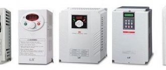
How to choose a frequency converter?
If you analyze the prices and functions of frequency converters, you can understand that the price determines the number of built-in functions of the frequency converter. Expensive models have great functionality. But to select a device, it is better to be guided by the required conditions of use.
- Frequency generators come with two types of control: scalar and vector. With scalar control, the device operates at certain values of the output potential difference and frequency; they work in primitive household appliances, for example, fans. With vector control, the current strength is set quite accurately.
- When choosing a device, power parameters play a decisive role. The amount of power expands the scope of use and simplifies maintenance.
- When choosing a device, the operating voltage range of the network is taken into account, which reduces the risk of its failure due to sudden changes in potential difference. If the voltage increases excessively, the network capacitors may explode.
- Frequency is an important factor. Its value is determined by production requirements. The lowest value indicates the possibility of using the speed in the optimal operating mode. To obtain a larger frequency range, frequency generators with vector control are used. In reality, inverters with a frequency range of 10 to 10 Hz are often used.
- A frequency converter that has many different outputs and inputs is convenient to use, but its cost is higher and configuration is more difficult. There are three types of frequency connectors: analog, discrete, digital. Reverse communication of input commands is carried out through analog connectors. Digital terminals input signals from digital type sensors.
- When choosing a frequency converter model, you need to evaluate the control bus. Its characteristics are matched to the inverter circuit, which determines the number of pads. The best choice is a frequency generator with a reserve number of connectors for further modernization of the device.
- Frequency drivers that can withstand heavy overloads (15% higher than the motor power) have preferences when choosing. To avoid making mistakes when purchasing a frequency converter, read the instructions. It contains the main parameters for operating the equipment. If you need a device for maximum loads, then you need to choose a frequency converter that keeps the current at peak operation higher than 10% of the nominal value.
Why is high crankshaft rotation speed harmful?
The “slipper to the floor” driving style implies constant spinning of the crankshaft up to 5–8 thousand revolutions per minute and late shifting of gears, when the noise of the engine literally rings in your ears. What are the consequences of this driving style, besides creating emergency situations on the road:
- all components and assemblies of the car, and not just the engine, experience maximum loads during their service life, which reduces the total resource by 15–20%;
- due to the intense heating of the engine, the slightest failure of the cooling system leads to major repairs due to overheating;
- exhaust pipes burn out much faster, and with them an expensive catalyst;
- transmission elements wear out quickly;
- Since the crankshaft rotation speed exceeds normal speed by almost twice, fuel consumption also increases by 2 times.
Running a car “to break” has an additional negative effect associated with the quality of the road surface. Driving at high speed on uneven roads literally kills suspension elements, and in the shortest possible time. It is enough to fly your wheel into a deep pothole and the front strut will bend or crack.
The general technical condition of the car, including its engine, cooling system, transmission and much more, can always be checked using a personal ODB-II auto scanner. One of the best representatives of this type of device is the Korean-made scanner Scan Tool Pro Black Edition.
In addition to accurate diagnostics of all components and assemblies of the car, the auto scanner is capable of displaying revolutions, oil pressure, readings from all sensors, etc. in real time. The scanner is compatible with most cars with an ODB-II connector and is quite easy to use. Information about the condition of your car can always be displayed on any device running iOS, Android or Windows.
How to connect a frequency converter
If the cable for connection is 220 V with 1st phase, a “triangle” circuit is used. You cannot connect a frequency converter if the output current is higher than 50% of the rated value.
If the power cable is three phase 380 V, then a “star” circuit is made. To make it easier to connect power, contacts and terminals with letter designations are provided.
- Contacts R, S, T are intended for connecting the power supply in phases.
- Terminals U, V, W serve as the motor connection. To reverse, just change the connection of the two wires to each other.
The device must have a block with a ground connection terminal. More details on how to connect are here.
How to maintain frequency converters?
For long-term operation of the inverter, it is necessary to monitor its condition and follow the maintenance instructions:
- Clean internal elements from dust. You can use a compressor to remove dust with compressed air. A vacuum cleaner is not suitable for these purposes.
- Periodically monitor the condition of the components and replace them. The service life of electrolytic capacitors is five years, fuse links are ten years. Cooling fans last 3 years before replacement. The wire loops have been used for six years.
- Monitoring the DC bus voltage and the temperature of the mechanisms is a necessary measure. At elevated temperatures, the thermal conductive paste dries out and damages the capacitors. Every 3 years, a layer of conductive paste is applied to the power terminals.
- The operating conditions and operating hours must be strictly observed. The ambient temperature should not exceed 40 degrees. Dust and humidity negatively affect the condition of the working elements of the device.
Frequency converter payback
Electricity is constantly becoming more expensive, and managers of organizations are forced to save in different ways. In industrial production, most of the energy is consumed by mechanisms with electric motors.
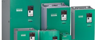
Manufacturers of devices for electrical machines and units offer special devices and instruments for controlling electric motors. Such devices save electrical energy. They are called inverters or frequency converters.
The financial costs of purchasing a frequency generator do not always justify the cost savings, since their cost is comparable to the cost of saved energy. It is not always possible to quickly equip a mechanism with an inverter. What difficulties arise in this? Let's look at ways to start asynchronous motors to understand the advantages of inverters.
Frequency regulation rules
The maximum of the new frequency depends on its mechanical properties.
At a higher rotation speed relative to the rated speed, asynchronous electric motors produce better energy performance than at a lower one. Therefore, in systems with a gearbox, it is useful to regulate the frequency both down and (especially) up to a maximum, which depends on the mechanical strength of the rotor. It is important to consider the following rule. When the number of shaft revolutions increases relative to the motor's nameplate data, the frequency of its power source should not increase by more than 1.5–2 times the nominal value.
This control method - frequency regulation of an asynchronous motor - is most justified in mechanisms with a squirrel-cage rotor. In its case, due to the absence of slipping, power losses remain minimal, and the output mechanical characteristics are of high rigidity.