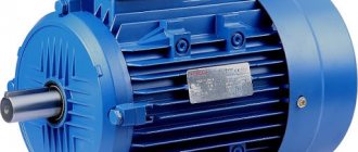
An induction motor converts electrical energy into mechanical energy. The mechanical characteristics of an asynchronous motor, electromechanical and others contain information without which its correct operation is impossible.
This design is quite widely used in various spheres of human life. Without them, the operation of machine tools, conveyors, and lifting and transport machines is unthinkable. Motors with low power are widely used in automation.
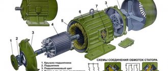
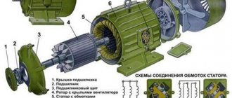
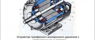
The device of an asynchronous machine
Schematic design of an asynchronous machine
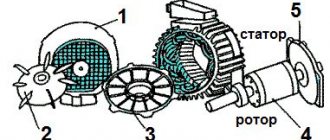
A classic asynchronous machine consists of 2 main parts: a rotor (moving) and a stator (fixed). Three separate phases make up the stator winding. C1, C2 and C3 - designations of the beginning of phases. C3, C4 and C5 are the ends of the phases, respectively. All of them are connected to the terminal connector according to a star or delta circuit, as shown in Figures a, b, c. The circuit is selected taking into account the engine rating data and mains voltage.
The stator creates a magnetic field inside the electric motor that constantly rotates.
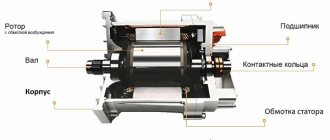
The rotor is distinguished between squirrel-cage and phase.
In short-circuited, the rotation speed is not adjustable. The design with it is simpler and cheaper. However, its starting torque is too small compared to machines with a wound rotor. Here the rotation speed is adjusted due to the possibility of introducing additional resistance.
Operating principle of an asynchronous machine
By applying voltage to the stator winding, changing magnetic fluxes can be observed in each phase, which are shifted by 120 degrees relative to each other. The total resulting flux is rotating and creates an emf inside the rotor conductors.
A current appears there, which, in interaction with the resulting flow, creates a starting torque. This causes the rotor to rotate.
Slip S occurs, i.e. the difference between the rotation frequency of the rotor itself n2 and the frequency of the stator magnetic field n1. Initially it is equal to 1. Subsequently, the frequency increases, the difference n1 – n2 decreases. This leads to a reduction in torque.
At idle the slip is minimal. It reaches a critical value Scr when the static moment increases. Exceeding Scr leads to unstable operation of the machine.
Performance characteristics of asynchronous motor
Performance characteristics of asynchronous motor
— dependence of the consumed current I1 and power P1, efficiency, cos φ and slip s on the useful mechanical power P2. These characteristics are determined at constant voltage U1 and network frequency f1.
Performance characteristics of asynchronous motor
can be obtained experimentally (experimentally) and calculated using an equivalent circuit.
The following is the calculation of the performance characteristics of an induction motor
according to the replacement scheme.
A multiphase current system, usually three-phase, flows through the stator winding of an asynchronous machine, which creates a rotating magnetic field (magnetic flux F) in the air gap of the machine.
The rotating magnetic field, in turn, induces (induces) an EMF in the conductors of the rotor winding, under the influence of which current I2 flows in the short-circuited rotor winding. This current, interacting with the magnetic flux F, creates a mechanical force that tends to cause the rotor to rotate in the direction of rotation of the magnetic field.
Let us determine at what rotational speed the magnetic field of the machine crosses the rotor conductors. This frequency is equal, rpm:
(9)
Let us determine the EMF frequency f2, which is induced by the magnetic field of the asynchronous machine in the rotor conductors, Hz:
f2=p n2/60. (10)
Considering that n2=n1s [see formula (9)], then we can write
(11)
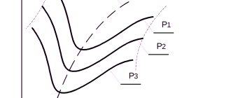
From formula (11) it is clear that if the rotor of the machine is stationary (n=0, s=l), then the frequency of the EMF induced in the rotor is equal to the network frequency. As the rotor speed increases, the EMF decreases and at synchronous frequency it will be equal to zero. In Fig. Figure 13 shows changes in slip, frequency and EMF in the rotor depending on the rotor speed.
Rice. 13. Dependence of slip s, frequency f2 and EMF induced in the rotor, E2, on the rotation speed of an asynchronous motor n
From the law of electromagnetic induction it follows that with a harmonic change in the magnetic field, the EMF induced in the winding is equal to:
E=4.44fwkobФmax, (12)
where f is the electrical frequency, Hz; w is the number of phase turns connected in series; kob - winding coefficient; Фmax is the maximum value of the working flux coupled to the winding, Wb.
Knowing the frequency f2 in the rotor makes it possible to determine the EMF of the rotor E2 at an arbitrary rotational speed (slip), B, in the form
E2=4.44f2w2kob2Фmax, (13)
where w2 is the number of series-connected turns of the rotor winding; kob2 is the rotor winding coefficient.
Substituting f2 from formula (11) gives, B,
E2s=4.44f s w2kob2Фmax=sE2, ( 14)
where E2 is the EMF induced in the stationary rotor winding by the flux Фmax, V.
Let us now highlight an important issue for analyzing the operation of asynchronous motors: the dependence of the rotating magnetic flux of the motor on the operating mode of the machine. To do this, in order to imagine this dependence, let us first determine what EMF E1 this flux induces in each phase of the stator winding, B:
E1=4.44fw1kob1Фmax, (15)
where w1 is the number of turns of one stator phase; kob1 is the winding coefficient of the stator winding.
The voltage U1 applied to the stator is balanced by the emf E1 and the voltage drop I1z1 across the internal resistance z1=r1+jx1 of the stator winding (x1 is the inductive reactance of the winding, determined by the leakage flux). When the engine load changes from zero (idling) to rated voltage, the voltage drop is 5-10% of the applied voltage. Thus, with sufficient accuracy for qualitative analysis, we can assume that the voltage U1 is completely compensated by the emf E1, i.e.
U1≈E1 (16)
Taking into account formula (15), it is easy to conclude that the EMF and the rotating magnetic flux of the motor depend on the voltage applied to the motor. At constant voltage, the flux Fmax remains approximately constant regardless of changes in engine load.
Let us first consider the phenomena occurring in a machine with a locked rotor and a short-circuited rotor winding. Asynchronous motor
in this mode it is similar to a transformer with a short-circuited secondary winding. The difference is that the secondary magnetic circuit is separated from the primary by an air gap, the primary winding (stator) and secondary winding (rotor) are evenly distributed around the circumference, and the magnetic field is rotating.
As can be seen from formula (14) and Fig. 13, the EMF induced in the rotor winding when it is stationary is maximum. Because of this, the current passing through the stator and rotor windings will also be the greatest. This mode is called short circuit (SC) mode. The stator current in this mode is called short-circuit current and exceeds its rated current by 4-7 times. Asynchronous motor
in such conditions, it is impossible to leave it under full voltage for a long time due to overheating of the windings, which can lead to an accident.
To determine the short circuit current of the motor, a short circuit experiment is performed. This experience consists in the fact that a reduced voltage is supplied to a motor with a braked (stationary) rotor, and by adjusting it, the rated current is set. The voltage supplied to the motor in the short circuit test turns out to be small (15-20%) compared to the nominal one. Based on this experience, it is possible, under conditions that are safe for the engine, to determine the value of the short circuit current /k at the rated voltage, A:
(17)
where Unom is the rated voltage, V; Uk is the voltage in the short circuit test at the rated current, V; Inom - rated current, A.
By measuring in this experiment with a wattmeter the short-circuit power Pk supplied to one phase of the motor, the power factor in the short-circuit mode is also found
(18)
and equivalent active resistance of the stator and rotor of the motor in short-circuit mode for one phase, Ohm,
rk=Pk/Inom2 (19)
This equivalent active resistance is equal to the sum of the stator active resistance and the reduced rotor active resistance. The concept of reduced active and reactive rotor resistance will be given below.
Having determined the angle φк from the value of cosφк from formula (18), it is easy to find the equivalent reactance of the motor in short circuit mode, Ohm:
xk=rкctgφк (20)
Inductive reactance xk is equal to the sum of the stator inductive reactance and the reduced rotor inductive reactance.
Since the engine rotor speed in this mode is zero, its mechanical power is also zero. The losses in steel during a short circuit experiment are very small, since the rotating magnetic flux is small. Therefore, the power Pk, which is supplied to the machine, almost all goes to heating the conductors of the stator and rotor windings. The same can be said about the short circuit mode at full voltage.
Now imagine that the rotor winding is open-circuited and the stator winding is connected to the network. In this case, no current passes through the rotor winding and the asynchronous motor
similar to a transformer, but in no-load mode (XX). Since there is no current in the rotor conductors, no mechanical force occurs and the rotor remains motionless.
In this case, the no-load current I0 passes through the stator winding, which creates the magnetomotive force (MFF) necessary to create the magnetic flux Фmax. Since there is a gap in the magnetic circuit of an induction motor, relatively more current is required to create magnetic flux than in a transformer. In high and medium power motors the current XX is 25-35, and in low power motors it is 35-60% of the rated current.
The EMF induced in a stationary rotor can be determined by formula (14), taking into account that slip in this mode is equal to 1. The ratio of the EMF in the stator winding to the EMF in the rotor winding is called the EMF transformation ratio and can be determined by the formula
(21)
The power consumed by the motor in mode XX with a stationary rotor is spent on losses in the motor stator conductors, losses due to magnetization reversal and eddy currents in the stator steel and in the rotor steel.
It is important to note that mode XX with a stationary rotor is very close to the mode that occurs when an induction motor
does not perform useful work and rotates at idle speed. In this case, the motor rotor speed is almost equal to synchronous, and the slip is approximately zero [see. formulas (4), (9) and fig. 13]. The electromotive force in the rotor will be close to zero, and, therefore, like mode XX with a stationary rotor, the current in the rotor is practically zero. During idling of a rotating motor, the current in the stator winding, as in the case of idling of a stationary motor, is determined mainly by the MMF necessary to create the magnetic flux Фmax.
When the rotor rotates, losses appear in the engine, which do not exist in the case of a stationary rotor; These are mechanical losses due to friction and ventilation. However, when the rotor speed is approximately equal to synchronous speed, losses in the steel of the motor rotor disappear, since the magnetic field now moves very slowly relative to the rotor and its steel is almost not remagnetized. Thus, the losses and, consequently, the power in the two idle modes turn out to be close.
An asynchronous machine in idle mode can be represented by the equivalent circuit shown in Fig. 14. To determine the parameters and characteristics of the motor, in addition to the short circuit test, experiment XX is performed, during which the stator winding current I0 (A) and power consumption P0 (W) are measured. This allows you to determine the resistance in the equivalent circuit of the engine at idle speed, as well as the power factor XX:
cosφ0=P0/(UI0). (22)
Rice. 14. Equivalent circuit of the primary circuit (stator) of an asynchronous motor operating in idle mode
Let us now move on to consider the general case of the load mode, when the rotor rotates at a frequency less than frequency XX. Let us determine what current will flow through the rotor winding over the entire range of operating modes. The EMF induced by the rotating magnetic flux in the rotor winding depends at a constant voltage only on slip and can be found from (14). The rotor current will obviously depend on the EMF induced in the rotor and the resistance of the rotor winding, while the total resistance of the circuit in the case of alternating current is determined not only by the active resistance of the winding conductors, but also by its inductive resistance. The inductive resistance of the rotor winding changes in the same way as the rotor EMF E2s, Ohm:
x2s=2πf2L2=s2πf1L2 =sx2, (23)
where L2 is the inductance of the rotor winding, H; x2—inductive leakage resistance of the stationary rotor winding at s=l, Ohm.
Now, using Ohm's law for alternating current circuits, we find the rotor current, A:
(24)
Taking into account (14) and (23), formula (24) can be written differently:
(25)
Thus, it can be seen that when slip is at or near zero (this corresponds to synchronous or near-synchronous rotor speed), the rotor current is zero or very small. This coincides with what was said above regarding mode XX with a rotating rotor. As the engine speed decreases, i.e., as slip increases, the current increases due to an increase in the rotor EMF, but the increase in current is limited by an increase in the rotor inductive reactance.
If we divide the numerator and denominator of expression (25) for the rotor current I2 by s, we obtain the following formula:
(26)
It follows from this that if we accept that the rotor is stationary, and its active resistance changes in inverse proportion to the slip, then exactly the same current will flow through its winding as with a rotating rotor. The convenience of this transformation is that it allows us to consider a stationary rotor (stationary secondary circuit) instead of a rotating rotor (rotating secondary electrical circuit).
However, the study of the processes occurring in an asynchronous machine and the calculation of its characteristics can be made more convenient if we replace the real rotor winding with an equivalent one with the number of turns in a phase and the number of phases equal to them in the primary winding (stator winding), i.e. instead of the rotor winding with the number of phases m2, the number of turns in the phase w2 and the winding coefficient kob2, we will assume that the rotor winding has the number of phases, the number of turns in the phase w1 and the winding coefficient kob1. This replacement is called bringing the rotor winding to the stator winding. It is easy to see that the magnetic flux Ф in this case will induce in the equivalent (reduced) rotor winding an EMF equal to the EMF of the stator winding E2'=E1 (we will denote the reduced values with a prime).
Replacing the rotor winding should not lead to a change in power consumption, losses, magnetomotive force or phase of the winding current. From this condition, the reduced values of current, active and inductive resistance of the rotor winding are determined.
In accordance with (13) we have, B
(27)
From formulas (27) follows the relationship between the reduced EMF and the real windings of the locked rotor, which is called the transformation coefficient of the EMF or voltage. It is equal to:
(28)
From the condition of invariance of magnetomotive forces F2′ =F2 it follows that
from which follows the relationship between the currents, which is called the current transformation ratio. It is equal to:
(29)
From the condition of invariance of losses in the rotor winding during reduction it follows that
where
(30)
or r2'=krr2,
where kr=kIkU is the resistance reduction coefficient.
From the condition of constant phase of the rotor winding current it follows
(31)
The process of bringing the rotor chain is shown in Fig. 15. From the equivalent circuit of the rotating rotor winding (Fig. 15, a) we move on to the equivalent circuit of the stationary rotor (Fig. 15, b), and then we bring the rotor winding to the stator winding (Fig. 15, c).
Rice. 15. Equivalent circuits: a - windings of a rotating rotor; b - stationary rotor; c - rotor winding connected to the stator winding
Since now the EMF E1 of the primary winding is equal to the EMF E2′ of the secondary winding, we can electrically connect the corresponding points of the equivalent circuit of the stator and rotor windings. As a result, we obtain the equivalent circuit of an asynchronous motor shown in Fig. 16. Here the active resistance rm reflects the presence of losses in the motor steel. For medium and high power engines, it is more convenient to use the simplified equivalent circuit shown in Fig. 17.
Rice. 16. T-shaped equivalent circuit of an asynchronous motor
Rice. 17. Simplified L-shaped equivalent circuit of an asynchronous motor
Using the latest diagram, it is easy to find the currents and EMF in the windings, the supplied and useful power, as well as the power losses at any engine speed. To do this, you just need to find the slip corresponding to a given frequency n using formula (4) and calculate the resistance r2'/s in the circuit according to Fig. 17. After this, it is not difficult to find the magnetizing current I0 and the reduced current I2′ in the rotor circuit, A:
(32)
This makes it possible to calculate the electrical losses in the stator winding of a three-phase motor (m1=3), W:
(33)
Electrical losses in the rotor winding (W) can be found by first calculating the reduced rotor resistance r2′ (Ohm) using (30):
(34)
The total active power transferred from the stator to the rotor, as can be seen from the diagram (Fig. 17), will be equal, W:
(35)
This power is transferred to the rotor electromagnetically and is therefore called electromagnetic power.
If we subtract the power of electrical losses in the rotor winding from the electromagnetic power, we obtain the total mechanical power of the motor, W:
(36)
Full mechanical power is spent on rotating the drive mechanism (useful mechanical power) and on covering the mechanical Rmkh.p and additional Rd.p losses of the engine itself. Therefore, the useful mechanical power P2 will be equal, W:
(37)
By definition, the efficiency of an engine is equal to the ratio of the output (useful mechanical) power to the consumed (active electrical) power. The difference between these powers is the losses in the engine, equal, W:
where Pm.p=m1I02rm - magnetic losses or losses in steel. Thus, the engine efficiency is:
(38)
The use of the first or second expression for efficiency is determined by which of the powers - P1 or P2 - is known. In practice, the first expression (38) is most often used.
Using an equivalent circuit, it is also possible to determine the current consumed by the motor from the network, i.e., the stator current, which is equal to the sum of two currents. The first of them is the current XX, which flows through circuit 1 (Fig. 17) and does not change when the rotor speed changes, the second is the rotor current I2′, which is determined by (32). By geometrically adding these two currents, you can get the stator winding current. This geometric addition is shown in Fig. 18. Angles φ2′, φ0 required for construction can be found using an equivalent circuit (see Fig. 17):
Thus, knowledge of the parameters of the equivalent circuit (r1, x1, r2′, x2′, rm, xm) and the applied voltage U1 (mains voltage) allows using the above formulas to determine the useful power, currents, losses, efficiency, power factor of the motor at various slips (rotation speed).
Rice. 18. Current diagram of an asynchronous motor
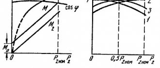
The dependences of the consumed current I1 and power P1, efficiency, cosφ and slip s on the useful mechanical power P2 are called engine performance characteristics. These characteristics are determined at constant voltage U1 and network frequency f1. An example of performance characteristics is shown in Fig. 19.
Rice. 19. Performance characteristics of asynchronous motor
Consider the performance characteristics of an asynchronous motor
. At idle (useful power P2 - 0), slip s is also equal to zero (rotor speed n is almost equal to synchronous), resistance r2/'s is equal to infinity (see Fig. 17) and current I2' = 0. No-load current I0 flows through the stator winding. The efficiency factor η is equal to zero, since the useful power P2 is zero, and the power factor is equal to the power factor for the no-load current (cosφ1=cosφ0).
As the load increases, the rotor speed decreases and slip s increases. Due to the increase in s, the resistance of circuit 2 decreases (see Fig. 17) and the rotor current increases, and therefore the stator current. As the net power increases, the engine efficiency increases, as does the power factor.
Typically, the rated power on the motor shaft is achieved already with a slight decrease in the rotor speed and the entire range of operating modes is in the slip range from 0 to 2-5%.
Therefore, the speed characteristic n=f(P2) of an asynchronous motor has a slight slope to the abscissa axis. Characteristics of this type are usually called hard. Accordingly, the characteristic s=f(P2) has a slight rise with increasing load. In an asynchronous motor, the rotor rotation frequency is less than the field rotation frequency, due to which the EMF is induced, as well as the creation of a 1% current in the rotor winding and a rotating electromagnetic torque, under the influence of which the rotor begins to rotate.
The characteristic cosφ=f(P2) lies in the range of values less than 1, since the asynchronous motor
always consumes current I0, almost independent of the load in the power range from P0 to P2≈Pnom. At XX usually φ0<0.2, i.e. it contains a large reactive component. As the load increases, cosφ quickly increases and reaches its maximum value at power Р2≈Р2nom. As the load increases above the rated load, cosφ decreases slightly.
The efficiency reaches its maximum value at P2≈ (0.6÷0.8)P2nom and decreases with further increase in load. Since the engine usually operates under a variable load varying within the range of (0.6-1) P2nom, the efficiency in this range of load changes should be quite high.
Mechanical characteristics
As the main one, it helps to conduct a detailed analysis of the operation of the electric motor. It expresses the direct dependence of the rotor speed on the electromagnetic torque n=f (M).
The graph shows that in sections 1-3 the machine operates stably. 3-4 - immediate segment of unstable work. Ideal idle speed corresponds to point 1.
Point 2 - nominal operating mode. Point 3 - the rotation speed has reached a critical value. Starting torque Mstart - point 4.
Our readers recommend! To save on electricity bills, our readers recommend the 'Electricity Saving Box'. Monthly payments will be 30-50% less than they were before using the saver. It removes the reactive component from the network, resulting in a reduction in load and, as a consequence, current consumption. Electrical appliances consume less electricity and costs are reduced.
There are technical methods for calculating and constructing mechanical characteristics taking into account data from the passport.
At the initial point 1 n0=60f/p (p is the number of pole pairs). Since nn and Mn are directly the coordinates of point 2, the rated torque is calculated using the formula Mn = 9.55*Рн/ nn, where Рн is the rated power. The value of nn is indicated in the engine passport. At point 3 Mkr=Mnλ. Starting torque at point 4 Mstart=Mn*λstart (values of λ, λstart - from the passport).
A mechanical characteristic constructed in this way is called natural. By changing other parameters you can obtain an artificial mechanical characteristic.
The results obtained make it possible to analyze and harmonize the mechanical properties of the engine itself and the working mechanism.
Electromechanical and mechanical characteristics of blood pressure.
Switching diagram and static characteristics of an asynchronous motor.
Asynchronous motors are widely used in industry due to the simplicity of their design, reliability and low cost.
A three-phase IM has a stator winding connected to a three-phase AC network with voltage U
and frequency
f
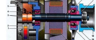
, and the rotor winding, which can be made in two versions. IM with a wound rotor (making a conventional three-phase winding of conductors with leads to three slip rings). IM with a squirrel-cage rotor - making the winding by pouring aluminum into the rotor slots (Figure 5.1). Single-phase equivalent circuit (Fig. 5.1)
Fig. Connection diagram of the IM with phase (a), squirrel-cage rotor (b), L-shaped single-phase equivalent circuit of the IM.
U1
– effective value of the voltage applied to one phase of the stator winding, frequency
f1
;
Fig Phase and line voltages
Iμ, I1, I'2 – phase currents of the magnetization, stator and rotor windings, respectively (reduced to the number of turns of the stator winding);
R1 – total active resistance of the stator phase;
R'2= R'р + R'2д – total active resistance of the rotor phase, reduced to the number of turns of the stator winding. Includes R'р, – the own resistance of the rotor winding (given); R'2д – additional active resistance (reduced).
x1, x'2 – inductive leakage resistances, respectively, of the phase of the stator winding, rotor winding (reduced to the number of turns of the stator winding);
Rμ – active resistance, taking into account losses in the steel of the magnetic system during magnetization reversal;
xμ – inductive resistance of the magnetization circuit.
When the stator is connected to a three-phase current network, its windings create a magnetic field F
, which rotates at speed
n1
.
E2
in it .
The magnitude of the EMF is proportional to the difference in the speeds of the stator and rotor fields:
E2~( n1- n)Ф
(#)
Along the rotor winding under the influence of EMF E2
currents will flow, creating a magnetic field in the rotor.
The magnetic field of the rotor interacts with the rotating field of the stator, creating a rotating torque. Having started to move, the rotor will “catch up” with the stator field. But an asynchronous motor always has n<n1
.
Otherwise, when equal, EMF E2
, currents, and the magnetic field of the rotor disappear, and braking begins.
The lag of the rotor from the stator magnetic field is called slip:
= (1)
Note that in the equivalent circuit the dependence R'2
from sliding
s
does not correspond to the physical essence of electromagnetic processes.
In fact, the inductive reactance of the rotor X'2 depends on the slip. So, X'2=ω2L2=2πf2L2 (*). At the same time, it is known that the frequency f2
of the EMF
E2
in the rotor winding depends on the slip
f2 = f1 s
. The transformation performed (division by s) made it possible to draw up an equivalent circuit.
Electromechanical and mechanical characteristics of blood pressure.
In contrast to the DPT, the electromechanical characteristic of the IM is presented in the form of a dependence of the rotor current on the slip I'2= f( s)
, and not on the speed ω. The electromechanical characteristic equation follows from the equivalent circuit:
(2)
At the same time, sliding uniquely determines the magnitude of the speed:
From (1) (3)
Therefore, when constructing the characteristics I'2(s), the dependence I'2
(ω).
Fig Electromechanical characteristics
In the graph, the current I1 is greater than the current I'2 in accordance with the equivalent circuit by the value of the no-load current Iμ (Kirchhoff's first law).
Let's consider the characteristic points of the electromechanical characteristics:
1) Ideal idle speed corresponds to the rotor rotation speed ω= ω0
,
slip s=0
(the rotor and stator field rotate synchronously), rotor current
I'2=0
, stator current
I1= Iμ
.
An asynchronous motor cannot provide this mode on its own. To create the mode, it is necessary to rotate it with a frequency ω=ω0
by another motor.
In the equivalent circuit, this mode corresponds to an open rotor circuit ( I'2
).
2) Short circuit (start mode) corresponds to the mode when ω=0
, slip
s=1
, rotor current
I'2= I'2p
, stator current
I1= I1p
.
The current I1p
is called the starting current and reaches 5-7 times the rated current.
, obtained by taking s=1;
3) stator and rotor currents I1, I'2
reach their maximum value at the minimum denominator of expression (2), when =>
This mode occurs at speeds above synchronous ω0
, i.e. in generator mode.
4) At high speeds ω=±∞
, s=
±∞,
the value of the rotor current asymptotically approaches the value
;
Let us obtain an expression for the mechanical characteristics. Power losses in the rotor circuit (sliding losses) are the difference between electromagnetic and useful mechanical power:
Power losses in the rotor, expressed in terms of electrical quantities:
=> , substituting current (2) into expression we get
Rice. Mechanical characteristics of blood pressure
To determine the critical slip sk
and the moment
Mk
we examine the obtained dependence M(s) on the extremum and we will find two points.
(5) (+ in motor, - in generator)
Dividing (4) by (5) and performing transformations, we get a more convenient form:
, where is the Kloss formula
For machines of medium and high power, the active resistance of the stator can be neglected, then a=0 and
(6)
In addition, in the region of small slips, s/sк can be neglected, then
(7)
From (6), designating how one can obtain expressions for finding sk
:
The formula can be used to determine sk
according to catalog data.
Let us analyze the features of the mechanical characteristics of blood pressure. It is non-linear and consists of two parts. The first - the working part - is within the sliding range from 0 to scd. This part of the characteristic is close to linear and has negative stiffness. Here the torque developed by the motor is approximately proportional to the stator and rotor currents. You can use expression (7).
The second part of the mechanical characteristics of blood pressure at s>skd is curvilinear, with a positive stiffness value. Despite the fact that the motor current increases as the slip increases (Figure 5.3), the torque, on the contrary, decreases.
Due to the nonlinearity of the mechanical characteristic, there is a discrepancy between the starting current (5-7 times) and the starting torque (0.4-0.5 rated). Hard start.
Let's look at the startup process.
The start starts with s=1, at the beginning of the start the slip is large. The inductive resistance of the rotor winding X'2=ω2L2=2πf2L2=2 πsf1L2 is large and significantly exceeds R'2. X2′>>R2′.
The EMF is high in this case, since ~Ф(n1-n)
Therefore, the current I'2 is also large, but its active component is small (because cosφ is low). Therefore, the torque developed by the engine is small.
2) When the engine accelerates, the slip decreases, the rotor EMF decreases, and the rotor current frequency f2 and X2′ decrease proportionally.
Accordingly, the total rotor current decreases. Active resistance becomes comparable to inductive resistance, and then becomes larger. Due to the increase in cosφ, the active component of the current increases, and the motor torque also increases.
Those. The uniqueness of the mechanical characteristics of the motor is determined by the dependence of the rotor inductive resistance on slip.