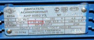
Asynchronous electric motors are complete systems, the quality of which is determined by technical characteristics. We will describe below why they are needed and how they are measured and changed. Engine parameters are the first thing you need to know before starting to operate it.
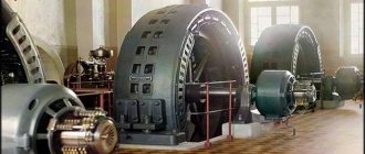
Asynchronous motor
In order to ensure the normal, coordinated operation of asynchronous power units, it is necessary to know everything about these motors, in particular, their operating and mechanical characteristics. This is necessary both when purchasing components in a store and when selling them yourself. Also, by properly regulating these indicators, you can successfully control the operation of the engine, ensuring not only high productivity, but also reduced energy costs.
Common parameters
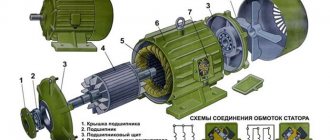
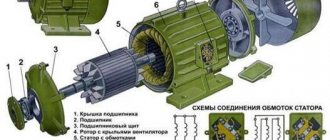
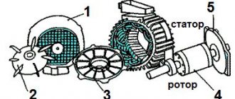
By default, a standard asynchronous type machine (without modifications or modifications) includes 2 main components:
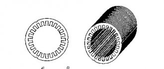
- stator – a stationary part;
- rotor is a part that can be rotated.
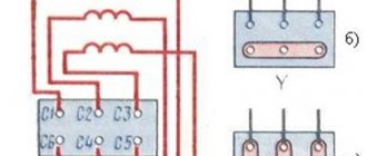
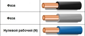
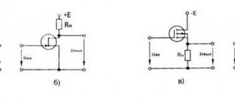
In three-phase models, the 3 separate phases represent the stator winding. C1, C2, C3 in the figure are their beginnings, and C3, C4, C5 are their ends. Absolutely all of them are connected to terminal connectors using one of two circuits: “star” or “delta”. In the image they can be seen under options B and C.
Asynchronous motor device diagram
The specific circuit for construction is selected taking into account the passport data of the electric motor and the mains voltage from which the power will be supplied.
The main task of the stator is to create a magnetic field inside the motor, which rotates uninterruptedly. There are two types of rotor - phase and short-circuited. The latter has a speed that cannot be controlled. The use of such a component in a power unit makes the design simpler and cheaper. The starting moment of such devices, however, is low, which cannot be said about motors with a wound rotor. Its rotation speed is controlled by introducing an auxiliary resistance.
Operating principle of the starting motor
The starter, like most single-cylinder two-stroke engines, runs on gasoline. The PD is equipped with spark plugs, high voltage wires and an electric starter.
The operating principle of the engine is as follows:
- During the transition of the distance between the bottom and top dead centers, the piston first closes the purge window, and then the inlet.
- The combustible mixture that has entered the combustion chamber during this time comes under pressure.
- The vacuum that appears at this moment in the crank mechanism transfers the combustible mixture from the carburetor to the crank chamber after the piston opens the intake window.
- Ignition of the fuel using a spark occurs at the moment when the piston is near TDC. Parts are lubricated by spraying fuel, which is mixed in a 1:1 ratio with oil.
The simple design of starting motors (PM) allows the use of fuel and oil of the lowest quality. The launcher is turned on by pressing the button located on its body.
Motor operating principle
The first thing that happens is that electrical voltage is applied to the stator winding. For each individual phase, you can see constantly changing magnetic fluxes, shifted relative to each other by an angle of 120 degrees. The result is a total resultant flux, which is also rotating, and with its help, an electromotive force is created inside the rotor conductors.
This is how the result is a current that is combined with the resulting flow, which creates the starting moment. And he, in turn, sets the rotor in motion.
This is a general, simplified description of the principle of operation of a power unit at different speeds. In order to consider the operation of the motor, it is worth delving into the mechanical and performance characteristics that precisely influence the operation algorithm described above.
PD adjustment and setup
Stable and correct operation of the launcher is possible only with the correct configuration of all mechanisms and parts. First, the carburetor is adjusted by setting the length of the rod that combines the throttle lever and the governor. Carburetor adjustment is carried out at low speeds.
The next step is to adjust the crankshaft speed using a spring. Changing the level of its compression allows you to adjust the number of revolutions. The last ones to regulate are the ignition system and the drive gear shutdown mechanism.
Mechanical characteristics
The essence of this parameter is the direct dependence of the rotor speed on the load indicators. That is, from the moment of rotation on the shaft. When the load is at the nominal level, the rotation speed for different types of motors varies in the range from 92.5 to 98% of the speed n1. Slip (Snom) does not exceed a level of 2 – 7.5%.
Mechanical characteristics
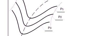
The higher the load level with which the motor operates, the lower the speed of the electric motor. The speed of an asynchronous motor decreases insignificantly as the load increases, ranging from zero to the maximum value. Visually, this can be seen above, in Figure A. It follows from this that the electric unit belongs to motors with a rigid mechanical characteristic.
M max., that is, the greatest torque, the unit develops when there is a certain slip (Skp), which is at a level of 10 to 20 percent. The ratio of the values Mmax and Mnom indicates the overload capacity of the motor. The ratio of Mn to nominal M indicates the starting qualities of the electric motor.
An electric motor is capable of stable and uninterrupted operation provided that self-regulation is ensured, when a balance is automatically established between the load torque aimed at the shaft (Mvn) and the M torque, which is developed directly by the engine. This condition is perfectly displayed at the top of the characteristic, when the maximum indicator M is reached. In other words, to the level of point B.
In situations where the load torque M exceeds Mmax, the motor has reduced stability and stops. In parallel with this, a current several times higher than the rated current will be supplied to the machine windings for quite a long time, which can lead to burnout. The temperature of the parts increases due to excess electricity.
When connecting the rotor windings from the starting rheostat to the electrical circuit, we get a full set of mechanical characteristics at the output. The first parameter when operating a motor without a starting rheostat is called the natural characteristic. The second, third and fourth indicators, which are obtained when connecting a rheostat to the rotor winding of the motor, have resistances R1p (2p and 3p, respectively), and relate to the mechanical characteristics of the rheostat type.
When the starting rheostat is started, the mechanical characteristic is called soft or steeply falling. This is due to the fact that the active resistance index of the rotor chain R2 increases significantly and Scr increases. At the same time, the starting current is reduced. This value (Mp) is also regulated by R2. At the same time, it is possible to select a rheostat with a certain resistance so that the starting moment (Mn) is equal to the maximum M.
Electromechanical characteristics
The indicator is the dependence of the angular speed of revolutions on the stator current. By using several control points at once, you can create such a characteristic. To do this, calculate the following values:
- rated current:
Example calculation
- critical slip:
Calculation
- current level at the initial moments of start.
Initial starting moment
All these values reflect the electromechanical characteristic as accurately as possible.
Starting motor device
The design of the PD consists of:
- Power systems.
- Starting motor gearbox.
- Crank mechanism.
- Ostova.
- Ignition systems.
- Regulator.
The engine frame consists of a cylinder, crankcase and cylinder head. The crankcase parts are connected to each other by bolts. The pins outline the center of the starting motor. The transmission gears are protected by a special cover and are located in the front part of the crankcase, the cylinder is in the upper part. Double cast walls create a jacket into which water is supplied through a pipe. Wells connected by two purge ports allow the mixture to enter the crankcase.
By design, starting engines are two-stroke starting engines paired with modified diesel engines. The engines are equipped with a single-mode centrifugal regulator directly connected to the carburetor. The stability of the crankshaft, as well as the opening and closing of the throttle valve, are adjusted automatically. Despite its low power (only 10 horsepower), the PD can rotate the crankshaft at a speed of 3500 rpm.
Performance characteristics
These parameters indicate the dependence on the useful power P2 = P max. such indicators:
- rotation (n) or slip (S) frequencies;
- gross moment (M2);
- stator current I1;
- Efficiency (coefficient of efficiency).
Performance characteristics
In this case, the values of frequency f1 and voltage U1 must be at nominal levels. They are implemented for areas of stable motor operation. This means that the range should be from zero slip to one that exceeds the nominal by 10 - 20%.
The speed of revolutions with increasing power output is difficult to change. This could already be seen in the mechanical characteristics, when the gross torque M2 is proportional to the power indicator P2. The torque is lower than the electromagnetic torque, the difference is the value of the braking torque Mtr, which is generated by friction forces.
The stator current I1 increases with the power output, but when P2 is zero, there is a certain current for idling - I0. The efficiency level also decreases, almost identically to that of a transformer, while maintaining a fairly high value over a relatively wide range of loads.
The highest efficiency for asynchronous power units with medium and high power varies between 0.75 - 0.95. The higher the power of the machine, the greater its efficiency.
The power coefficient cosine ϕ1 for asynchronous motors of similar characteristics with a maximum load is 0.7 - 0.9.
Based on this, it can be seen that power units overload electrical substations and power networks with their rather impressive currents, which can reach from 40 to 70% of the rated currents. This is one of the most significant disadvantages of installations of this type.
If the motor loads are an order of magnitude smaller, for example 25 - 50% of the workers, then the power coefficient drops to insufficient values - 0.5 - 0.75. When the load is removed from the motor, the power factor decreases further and the new indicators are 0.25 - 0.3. That is why it is impossible to allow an asynchronous motor to operate for a long time at idle speed, as well as at significant underloads.
PD models
Some models of launchers are still used on tractors and special equipment of various brands and models.
- PD-8. Single-cylinder two-stroke engine with a power of 5.1 kW. The crankshaft rotation speed is 4300 rpm. The fuel mixture is formed externally using a carburetor. The diameter and stroke of the cylinder are the same and amount to 62 millimeters, the working volume is 0.2 liters. The fuel compression ratio is 6.6. A mixture of diesel oil and gasoline in a ratio of 1:15 is used as fuel.
- PD-10. Single-cylinder two-stroke engine with crank-chamber scavenging. Mixture formation is external, using a carburetor. The cylinder stroke is 85 millimeters, diameter is 72 millimeters, volume is 0.346 liters. Torque - 25 N/m, fuel compression ratio - 7.5.
- P-350. Single-cylinder two-stroke starting engine with crank-chamber purge. The formation of the mixture is carburetor. The cylinder stroke is 85 millimeters, the diameter is 72 millimeters, the cylinder volume is 0.364 liters. Torque is 25 N/m, compression ratio is 7.5.
Adjusting the gearbox activation mechanism
The gearbox activation mechanism is adjusted by moving the clutch control lever to the engaged position by turning it counterclockwise all the way. The deviation of the lever from the vertical should not exceed 45-55 degrees.
To adjust the angle without changing the shaft, unscrew the bolts, remove the lever from the splines and install it in the required position, after which the bolts are tightened. The starting gear, or bendix, must be in the off position, for which the lever is rotated counterclockwise without moving.
The length of the rod is adjusted with a threaded fork so that it fits over the levers. The pin of the trigger gear lever should occupy the leftmost position of the slot. The maximum gap between the finger and the slot should not exceed 2 millimeters. The pins are pinned after installing the linkage, then the fork locknuts are tightened. The lever is returned to the vertical position and connected to the rod. The clutch regulates the length of the rod.
After adjusting the mechanism, you need to make sure that the lever moves without jamming. The operation of the mechanism is checked upon startup. The starting gear should not grind while the starting motor is running.
With proper adjustment and configuration of all mechanisms and parts, stable engine operation is ensured.
Adjusting the ignition timing
The ignition timing of the starting engine is adjusted after unscrewing the spark plug. The depth gauge of a caliper is lowered into the cylinder hole. The minimum distance to the piston bottom is indicated by a depth gauge at the moment the crankshaft turns and the piston rises to top dead center. After this, the crankshaft turns in the opposite direction, and the piston drops below the dead center by 5.8 millimeters. The contacts of the magneto breaker must be opened by the rotor cam. If this does not happen, then the magneto rotates until the contacts open and is fixed in this position.
Advantages of starting internal combustion engines and requirements for them
Among the advantages of the engines, they note the possibility of heating the engine oil in the crankcase using exhaust gases and warming up the cooling system by circulating coolant through the cooling jacket.
Carburetor engines are fundamentally different from other engines in their power supply system, which includes a fuel system and devices that supply it with air.
Basic requirements for carburetors:
- Fast and reliable engine starting.
- Fine atomization of fuel.
- Ensuring fast and reliable engine starting.
- Precise fuel dosing to ensure excellent power and economic performance in all engine operating modes.
- The ability to smoothly and quickly change the engine operating mode.