Often when carrying out repair work, the problem arises of how to find the wiring in the wall. Damage to a cable while drilling into a wall or driving in fasteners can not only result in a power outage, but also cause serious injury to a worker. To search for hidden wiring at home, you can use several methods that differ in their accuracy and efficiency.
What is a multimeter
A multimeter device is used mainly for measuring voltage, current and resistance in an electrical circuit and in its individual sections. Simply put, the device in one shell has a voltmeter, ammeter and ohmmeter.
Depending on the device and the number of additional options, it is used to study the integrity of an electrical circuit, monitor and measure the characteristics of its components.
The device can also measure direct and alternating current.
When measuring each characteristic (current, voltage, resistance, etc.), you first need to:
- visually determine the measurement scale. So, for a battery it will be 1.5V, 7.5V, 12V and higher. The value must be taken more than necessary. Simply put, this is a “strength reserve” so as not to break the device;
- choose the correct measuring direction. In this case, it is necessary to move the device pointer to the required position, based on the generally accepted parameters indicated on the body;
- connect the probes correctly. For any type of measurement, the negative (black) probe is inserted into the common socket (COM), the positive one is connected into the socket required for a specific type of measurement.
How to determine where electrical wiring runs in a wall
It is often possible to find out the cable routing diagram without using special instruments.
Visual method
The method is used under the following circumstances:
- it is planned to renovate the premises, providing for a complete replacement of the plaster of the walls;
- The wiring is mounted in such a way that it is visually easy to detect its initial sections.
According to current regulations, electrical cables are only allowed to be laid in straight lines. In this case, the wires can be mounted in a vertical or horizontal direction. Cables may only cross at a 90 degree angle.
Thus, having found the initial section of the wire, you can determine the laying pattern without removing the plaster from the walls.
The accuracy of the method depends on whether the wiring was installed in accordance with the rules of the Electrical Installation Code.
Why do you need to ring wires?
The process of testing the wire is necessary in order to find out its functionality. Using a simple device you can find a break, short circuit, defects or moisture in the wire. A professional multimeter finds the distance to a break.
Checking the wire is necessary when a repairman or homeowner is looking for the source of failure of electrical appliances, including household appliances, carriers, and sockets. Also, the wire is tapped before installing the wiring.
How to connect multimeter wires
A device called a multimeter is capable of measuring the voltage of different nodes of the electrical network, checking equipment for operability, measuring the resistance of the current in its direction, and much more.
Multimeters, given their models and set of configurations, may have a certain set of built-in capabilities. For example, the simplest devices are only capable of measuring current, but more advanced models are capable of solving many more diverse problems.
Devices are digital and analog. Depending on their type, they have a distinctive appearance, sometimes with different scale markings. However, the operating scheme for all of them will be identical.
Connecting the wires is the main procedure for starting any measurement. First, you need to learn the name of each connector located on the case, as a rule, there are 3 of them:
- COM – the black wire is always connected inside this marking.
- VΩmA – for the red wire. Used to check voltage or current (up to 200mA), calculate resistance.
- 10 ADC – also for red, but with slightly different tasks: current strength more than 200 mA.
It is extremely important not to confuse the purpose of a particular connector and use each according to its capabilities. Otherwise, there is a high risk of the multimeter failing.
After connecting the wires to the required holes, all that remains is to connect them to the terminals of the device that needs to be checked.
Rules for using the dialer
The only rule that needs to be remembered is that the dialing process is allowed only in a completely de-energized circuit.
Note! If you check live wires, you can get an electric shock and, in some cases, cause a fire.
Below we describe in detail how to check the wire with and without a multimeter.
How to properly test wires (with a multimeter and without instruments)
Step-by-step work process:
- before starting work, you must turn the multimeter handle to the desired position;
- connect the ends of the probes to the required sockets. The black probe goes into the socket marked COM (in some cases indicated as “*” or ground point), and the red one goes into the socket marked Ω (sometimes indicated as R). It must be emphasized that the symbol Ω can be drawn either alone or in combination with the designations of other signs (V, mA). This arrangement of wires will help maintain polarity when making future measurements;
- turn on the multimeter. Basically, there is a separate button for this or work can start automatically when the handle is turned to the required position;
- close the measuring ends to each other. If a beep is heard, the device is working correctly;
- take the wire to be tested (strip it of insulation in advance). Touch the exposed parts of the cable with measuring probes;
- If it is working properly, a sound will sound and the multimeter readings will be zero or show resistance. If the screen shows 1 and there are no sounds, it means that the tested cable is broken.
You can ring the wires without using a multimeter. To work you will need:
- a classic battery (it is advisable to take a 4.5-volt square battery);
- a regular 4-volt light bulb, through which the linear section of the cable is diagnosed (monitored);
- A pair of jumper cables and a breathtaking looking connector.
After preparing the tools for work, you need to use them to assemble a simple measuring circuit. If the circuit is correctly assembled and the wire is in good condition, the lamp will work. If there is a defect in the area, the light will not light up.
Safety rules for using a multimeter
When working with electrical devices, you should follow the safety instructions:
- Properly turn off and on electrical circuits. Carefully monitor the position of the circuit breaker.
- When working with live devices, protective equipment should be used. The tool must be insulated, and hands must be protected with rubberized gloves. It is recommended to use an insulating mat under your feet. Clothing should not be flammable.
- When measuring live devices with a multimeter, first connect the grounding clamp, and then the electrical wire. When disconnecting, the live wire is removed first, and then the grounding rod.
- The electrical appliance being tested should not be held in your hands. Any energized device must be kept at a blade-free distance from a person.
- Do not use the multimeter wet or use the measuring device in a damp environment.
- During the measurement process, it is prohibited to change the position of the switch in the multimeter. The limit of calculated values should only be adjusted when the probes are disabled.
- Before working with an electrical measuring device, you should check the serviceability of the test leads. It is prohibited to check voltage with parameters above the upper measurement limit of the device.
When selecting a multimeter, you need to clearly study all the technical parameters of the device, which are indicated in the documents attached to it. By taking all precautions and having an understanding of the principles of working with a measuring device, you can measure the voltage in electrical outlets every time you connect new electrical equipment.
How to detect a short circuit
Step-by-step instructions on how to determine a short circuit with a multimeter:
- When electrical devices and the network are turned off, you need to measure the circuit resistance in individual nodes. If possible, it is advisable to use a wiring diagram for the electrical supply of a house or apartment. If a lot of resistance is shown, then this section is working. And in places with a short circuit, the resistance will be 0. However, the device can also display a high resistance indicator, mainly if there is a large distance to the short circuit. For this option, it is advisable to use a megohmmeter;
- if there are no such devices, then you can use a test lamp with an independent current source. You can equip a regular flashlight with probes for this (the light bulb should work when the pins are connected to each other). By closing the required network cores one after another at the connections of the distribution boxes, a short circuit can be detected by a working lamp;
- remove the damaged cable. There is no need to perform spot installation of electrical wiring. Firstly, hidden wiring is located under the facing material, which means additional costs for installation work. Secondly, it is recommended to replace the entire damaged cable, since the short circuit may occur again. It is advisable to place the new cable behind the baseboard. Using a special box, connect it to an outlet.
Troubleshooting
A superficial check can be done using the command to ping all hosts on the home network and several remote Internet servers. For these purposes, open a command prompt as an administrator. Next, enter the commands, focusing on the algorithm of actions:
- Testing the operation of the network card of the computer itself is done by exchanging test packets with itself. If there are no losses, then everything is in order. The ping 127.1.1.0 command.
- You can add the -t option to make the packets go on forever until you manually stop them with the Ctrl+C key combination.
- Next, ping the area to the router. It is important to ensure that the Internet cable between the computer and the router does not break. If there are packet losses, reboot the router and try pinging again. If the local IP address of the router has not changed, then it is 192.168.0.1 or 192.168.1.1.
- When 100% of the number of packets reaches the router, the next step is to ping one of the remote servers. This way you can check if you can access the Internet. It is recommended to ping the IP address of the server of a large corporation, as this eliminates the fact that it is unavailable on the network. It is not necessary to know the IP address; you can ping by domain name.
Analyze the information received.
Safety regulations
Basic rules that must be followed when working with a multimeter:
- The best method would be to use so-called crocodiles, which will simplify the work. They will make the contact stronger and do not occupy your hands while working;
- Before testing the circuit, it must be disconnected from the network. It is necessary to remove even simple batteries from the circuit, and if there are capacitors, they must be short-circuited, thus discharging them. If you miss this nuance, the device will deteriorate;
- When checking a long wire, it is forbidden to touch bare areas with your hands, as the indicators may give an error.
In conclusion, it should be noted that using a multimeter is quite simple. All safety rules and instructions must be followed. It is recommended to have this device in every home and from time to time determine whether there is a short circuit or malfunction.
Checking with a dial multimeter
This is almost the easiest way to ring a cable, since such a device is found in almost every home. To check, take green and orange pairs of veins. The procedure is as follows:
- switch the device to search for resistance;
- touch the orange veins with a chisel;
- the resistance should be set at several ohms;
- touch the green veins and carry out a similar check;
- touch the orange and green veins and get a resistance value of 100 Ohms and above.
If the measurement was successful and showed the same numbers, then this indicates the excellent condition of the wires. If pairs do not ring through, it is necessary to replace them with unused ones, for example, brown or blue.
Why is the mode called “dialing”?
It was possible to check the integrity of the circuit before using the resistance measurement mode - an ohmmeter. The main difference between dialing is that during measurements, if there is an electrical connection between the tested areas, then, in addition to the readings on the screen, a sound signal is heard - a buzzer, which is where the term dialing or ringing arose.
This sound signal significantly speeds up the verification process, you don’t have to be distracted, look at the screen, and it’s not always convenient, and when you hear the buzzer (or not), you already know the result. This is especially useful for mass measurements, for example, when searching for one specific wire in a bundle.
Continuity indication on a multimeter
In one of the recent articles - “How to use a multimeter”, I already talked about the main operating modes of a standard tester, measurement limits and testing methods, in particular about the dialing function, which has the following designation:
As you can see, the marking accurately conveys the main meaning of this mode, because it consists of two elements - a diode icon, which symbolizes the test, and a buzzer, indicating a sound signal.
Operating principle of dialing
For a better understanding of how exactly the multimeter finds out whether there is an open circuit or not, I will, in general terms, describe the principle of operation of this mode.
Everything here is extremely simple, the operating principle of dialing is based on the well-known Ohm’s law, the main rule of electrical engineering:
I = U / R , where I – current, U – network voltage, R – resistance
Each multimeter has a power source - a battery or an accumulator, with the help of which a voltage is created on the section of the network being tested - a current is supplied and, knowing its characteristics, the result is calculated.
Tester is an excellent way to check
Using a tester is the best way to find out if there are cable breaks. Before starting the test, you should inspect the cable along its entire length, and especially pay attention to the quality of the crimp on the plug. If the crimp is bad, there will be problems with the contact of some wires. They can also be overlapped in a fixed position. This way they won't close themselves off. If a breakdown cannot be detected at first glance, then you can use a tester that will provide a quality check.
Important! Modern testers have great functionality and are easy to use thanks to their displays. They allow you to ring the cable and accurately determine the location of the break and short circuit. We can recommend the Tester MicroScanner Pro model.
This is one of the most popular devices on the market because it has many features, including:
- determining the degree of correctness of the wiring;
- determining the location of the breakdown;
- determination of the type of failure;
- determining the distance to the breakdown site;
- wire tracing product.
Such a device is good, but only if you have a multimeter or a regular pointer tester at hand. They will help you measure the resistance in the circuit, voltage and type of current. A multimeter may well be enough to analyze a twisted pair cable. To start the analysis, you need to turn on the resistance mode and bring the ends of the cable to one point. If this happens, then further verification is carried out in the following order:
- checking the integrity of all cable cores separately;
- testing each cable by color;
- checking for short circuits with adjacent conductors;
It often happens that it is impossible to make ends meet. Then the connector is either cut, or the wires at one end are stripped and connected to each other. After this, the pairs at the other end are probed with a multimeter.
What does the multimeter show when making a call?
The multimeter, when tested, shows the calculated voltage drop in millivolts in this circuit.
The current created by the tester in the area being tested, about 1 milliampere, was not chosen by chance, since the voltage drop in millivolts in this case corresponds to the resistance in Ohms.
In other words, when testing electrical circuits or electrical materials, we are shown the magnitude of the voltage drop, which is equal to the resistance of this section in Ohms.
As a result
Even a budget universal measuring device - a multimeter - allows you to take measurements within a fairly wide range, sufficient for home use. But when buying a device, you need to at least have a general idea of what purposes it will be used for - it may be better to overpay a little, but as a result, have a tester on hand that can perform any task assigned to it. Also, before using it, it would not hurt to at least in general refresh your memory of the basics of constructing electrical circuits and using electrical measuring instruments in them.
Previous
MiscellaneousCapacitor Energy
Next
MiscellaneousCircuit breakers
Testing the wire with a multimeter
1. Install the probes into the multimeter connectors:
– Red probe into the V Ω mA
– Black probe into COM
2. We switch the control wheel to dialing mode, which is marked accordingly (diode and buzzer icon). One should appear on the screen.
3. We check the correct operation of the multimeter by connecting the contacts of the probes by shorting them.
If the device is working correctly, you will hear a buzzer sound and a value close to zero will appear on the screen.
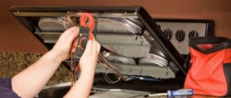
4. We call the wire. By applying the multimeter probes to its wires on both sides, as shown in the image below. If the conductor is intact, then you will immediately hear a buzzer sound, and the readings on the screen will be close to “0”, for example 0.001.
If the wire core is damaged and one of its ends does not have an electrical connection with the other, then the multimeter readings will not change, “1” will be displayed and there will be no sound signal.
As you can see, everything is quite simple, and if you have a multimeter at hand, you can try to ring something yourself. Just let me remind you once again - do not call under voltage, even under low voltage.
One of the clear, often found in everyday life, examples of checking wiring with a multimeter is described in our next article - HOW TO RING AN OUTLET. This is a detailed, step-by-step instruction for diagnosing a non-working outlet; be sure to study it to understand how to connect the electrical wiring.
How to measure the voltage in an outlet
One of the most common tasks is measuring the voltage in an outlet or in apartment wiring. This is very easy to do with a multimeter. As we already wrote above, alternating current flows in sockets, so to measure it you need to set the switch on the multimeter to the ACV zone.
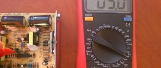
We know that the voltage should be approximately 220 volts, so if you have a multimeter like the example in the photo above, set the switch to a mark higher than the expected value, in this case 750 in the ACV range.
Having set up the device, it’s time to put your probe fingers into the socket. It makes no difference which wire is inserted into which hole in the socket. In general, there is nothing to be afraid of here, the main thing is to hold on to the insulated part of the probes and not touch their metal part (although this is quite difficult to do even with a strong desire), and also not to allow them to touch each other while they are inserted into the socket, otherwise you can cause a short circuit .
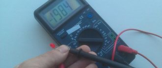
If you did everything correctly, the screen of your multimeter will show the current voltage in the outlet and your indoor wiring.
It will be interesting➡ Capacitor charge
In our case, this is 235.8 volts – within normal limits. You will never see exactly 220V on the screen, so an error of +-20 is normal.
What will it show if the socket is faulty?
If there is no network, the multimeter will read 0 Volts. The reason is a faulty socket or lack of electricity. To determine the cause, you need to ring other outlets in the room. If only one does not work, its contacts are checked and, if necessary, replaced with a new one.
During voltage surges, the values on the multitester will differ greatly from the nominal 220 Volts. According to GOST, a deviation of 10% is permissible; a larger deviation can lead to damage to electrical appliances. If a strong voltage surge is detected, it is worth installing an additional stabilization device in the apartment.
The home network operates at a voltage of 220 Volts, but in the outlet it may differ from the nominal value. Voltage within the limits established by GOST is the key to high-quality and stable operation of household appliances. It is important to be able to check voltage using a multitester to prevent the risk of damage to electrical devices. If there is a significant deviation from the set values, care should be taken to stabilize the voltage in the room.
What to do if the multimeter does not have a dialing mode
Some budget electronic testers do not have a separate dialing mode with a sound alert, but they can also check the integrity of the circuit , but this is not so convenient.
For example, the fairly popular dt 830b does not have a buzzer, but there is a diode test mode, you can use it by observing the change in readings on the screen. The probes are connected in the same way as described above into the COM and V Ω mA .
If the readings on the screen during measurements differ from one, then there is an electrical connection in the area being tested. You can check the functionality of this method by connecting the probes; if everything is in order, then zeros should appear on the screen.
In multimeter models, where there are no additional functions at all, in particular in analog instruments, you can ring by switching the regulator to the resistance measurement mode - ohmmeter.
In this case, it is necessary to select the lowest available threshold - for example, 50 Ohms or 200 Ohms. Then measure according to the usual scheme described above and watch the changes in the readings on the screen - if there are changes, the circuit is intact. For home, everyday conditions, this is quite enough to find which wire is broken, determine the burnt track on the board, and much more.
That's all for me; in my opinion, this information is quite enough for anyone to learn how to dial with a multimeter, even without ever doing it before. If you still have questions or have healthy criticism or additions, be sure to write in the comments to the article, in addition, subscribe to our VKONTAKTE group - stay tuned for new materials.
In the following articles we will talk about other useful functions and ways to use a digital multimeter in everyday life, determine the phase and zero in an outlet, measure the voltage in the network and much more, stay tuned .
How to check voltage with a multimeter
The thematic article “How to use a multimeter: detailed instructions for beginners” will help you understand the general principles of operation of the device. Here we will talk about using the device to work with sockets and other household electrical appliances.
The simplest multimeters used for household needs “can” measure current, voltage and resistance for AC and DC devices. If you need to check the voltage in a 220 V socket with a multimeter, the device regulator is set to the “alternating” voltage measurement area, marked V~ or ACV (depending on the multimeter model).
In this case, taking into account the possible excess of voltage in the network of standard indicators, the regulator is set to the maximum value - 750 V. After turning on the device, the display should show three zeros (depending on the number of digits of the device - there can be from 2.5 to 8.5 - the number of zeros may differ).
Next you need to connect the probes. They are mounted like this: black in a socket marked COMMON (COM), red - or in a socket marked VΩmA.
Important: to make it easier to navigate the symbols on the front panel of the multimeter, we recommend studying the standard marking options.
The probes are installed in both sockets of the socket. The display will show the AC voltage value at that point in the network. If, when asked how to measure the voltage in a socket with a multimeter, the user is “stuck” on the choice of which hole to insert which probe into, we can reassure you. This is not important; in most modern instruments, the polarity of the probes when measuring voltage is not important.
Important: if you need to clarify how to measure the voltage with a multimeter in the socket of a low-power extension cord or in an old, Soviet-style electrical network, you can install the positive probe in the socket marked mA. In this case, overloading the device is practically eliminated.
Cable testing is an essential tool for an electrician.
The standard and most common case is when there is no voltage in any outlet or lighting fixture, and sometimes in all of them at once. In this option, there is no choice - it is necessary to test the cable that powers the entire system, and then individual wires.
As a rule, in the distribution boxes of apartment buildings there is a tangle of unmarked and somehow insulated ends. Switches and sockets, especially in old houses, have long outlived their useful life. It is not easy to understand this intricacy and determine the specific place where the circuit break occurred. We have to check all the elements and re-label the cable cores.
Checking wires from light bulbs and batteries
In order to assemble a device for testing wires and cables, it is not necessary to have any knowledge of electronics or radio engineering. No need to understand diodes, resistors or capacitors. Today I will show you how to make a wire harness from a regular battery and a light bulb.
So, the need for such a device arose when I disconnected distribution boxes. That is, it was necessary to determine where and where which wire goes.
Of course, when there are two or three wires in the circuit, it is not difficult to determine the direction of the lines in the box, but you must admit that if the wiring is done in dozens of directions, it is extremely not easy to do such work.
One day I was asked to assemble junction boxes. That is, the situation was such that people hired electricians to install electrical wiring. These electricians did some of the work, took money for it, and disappeared somewhere.
Of course, they did most of the work, namely, they laid the wires, brought all the ends into the sockets and distribution boxes, and so on in the little things, they installed spotlights. This is where all their work ended.
All that remained was to install sockets and switches and connect the wires in the junction boxes, which is what they called me for. The customer was in a panic and asked me to finish all the electrical work as soon as possible so that everything would finally work.
There were 8-10 wires going into the distribution boxes in different directions and it was easy to determine which one was going where, especially if you didn’t do the wiring. This is where the need for such a device as a wire tester became necessary.
This is a device that consists of a light bulb, a battery, probes and connecting wires between them.
6 Volt light bulb. Initially, the battery was installed on the crown at 9 Volts, but over time it became addictive and I installed four ordinary AA batteries of 1.5 Volts each in its case and connected them in series. That is, in total they also give 6 Volts.
The connecting wires between them are the most common, thin, flexible. It is very important here that their length is sufficient for continuity of wires over long distances.
For ease of measurement, an alligator clip was installed on one end of the probe.
This is convenient in the sense that, for example, the boxes are in different rooms and in order to ring the cable, we attach the crocodile in one box, go to another and check. That is, you can handle this kind of work yourself.
Multimeter scale markings
Different device models have their own characteristics, but their basic capabilities are approximately the same, especially for budget models.
The simplest instruments can measure:
- ACV – alternating voltage. Setting the switch to this division turns the multimeter into a voltage tester, usually up to 750 and 200 volts;
- DCA – direct current strength. Here you need to be careful - on the scale of many budget devices there are measurement limits of 2000µ (microamperes) and 200m (milliamperes) and the plug must be left in the same terminal as when measuring voltage, and if current strength is measured up to 10 Amperes, then the plug must be rearranged to another terminal with the corresponding designation.
- 10A – DC current from 200 milliamps to 10 Amps. Usually it is written on the device that when you turn on this mode, you need to rearrange the plug.
- hFe – transistor check.
- >l – checking the integrity of diodes, but most often this function is used as a wire tester.
- Ω – measurement of the resistance of wires and resistors. Sensitivity from 200 ohms to 2000 kiloohms.
- DCV – constant voltage. Sensitivity can be set from 200 millivolts to 1000 volts.
Two wires are usually connected to the multimeter connectors - black and red. The plugs on them are the same, but the colors are different solely for the convenience of the user.