The only problem is the connection. Theoretically, it should be carried out by a professional electrician, especially since the warranty card for the device contains a clause for connection by a qualified electrician, confirming the correct implementation of connections to the network.
However, many are not born themselves, having knowledge of electrical engineering at the professional level. Perhaps you also feel the desire to buy an induction stove instead of a gas stove and would like to do everything yourself (again, saving...). The article below provides information on the different connection options and types of induction cooktops.
Induction hob power
The standard power of the induction hob is 7.2 kW. What does it mean? This is the maximum power consumption of the heating plate. When used daily with two or three burners, the stove will consume less energy. It will all depend on how quickly you need to heat up your food once you get home.
How is power converted into electric current?
1.Single-phase installation - in free conversion it will be:
I = 7200 W / 230 V = 31.3 Amps.
2. Three-phase networks with two phases are most often used. Each phase supports two heating fields with the same total power. Thus, for each phase the power is about 3600 W and the current is:
I = 3600 W / 230 V = 15.7 Amps.
Even if full power is rarely used, the electrical system must be prepared for a situation where all the "burners" are operating at maximum.
Electrical surface
First, let's talk about how to repair an electric hob and what problems this version of the stove may have. Most often, owners are faced with a situation where the hob does not work or one of the burners does not heat up when the power is connected.
In this case, the repair comes down to the following steps:
- Check the voltage in the outlet, because Perhaps this particular electrical point has failed, resulting in no power.
- Carefully inspect the cord and plug for mechanical damage. Sometimes the repair ends there - you just need to replace the electrical plug or cord.
- Remove the hob from the countertop by disconnecting all wires and unscrewing the mounting strips.
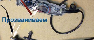
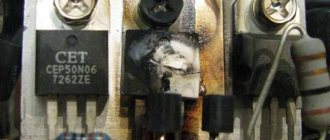
- Using a multimeter, check the thermal fuse (pictured below) and the transformer. If there is no resistance or differs from the nominal value, you need to replace the circuit elements with new ones.
- Check all wire connections (on the control unit, switches, thermostat, burners) and make sure that there is no simple open circuit. First, try to visually find the fault, and then use a multimeter to test all sections of the circuit according to the diagram.
Often, finding a breakdown of an electric hob with your own hands is not difficult if you know how to use a multimeter. If this device is not available, you can use an indicator screwdriver, which will show the presence of voltage in a certain section of the circuit.
In addition, I would like to tell you why the hob may stop working, so that you know the cause of the malfunction and how to repair each one. So, among the main breakdowns, the most common are the following:
- The fuse blows due to a power surge. Replacement is not difficult, and the cost of the fuse is negligible. To protect equipment from such a malfunction, it is recommended to install a network surge protection device.
- The burner (one or several at once) does not work. Most likely there was a break in the circuit on the heating element. If the wiring is unsoldered, DIY repairs will not be difficult if you have a soldering iron. If the heating element burns out, it must be replaced with a new one. They rang the heating element, but is it intact? Check the control unit; sometimes a contact break occurs on the switch, which needs to be either repaired or replaced.
- The sensor does not work. Here things are more serious, because... A touch-sensitive hob will be difficult to repair for a novice electrician. First, as in previous cases, ring the sensor. If you cannot find the banal cause of the malfunction, you will have to either replace the touch panel or send it in for repair. Typically, failure of this circuit element is extremely rare and is caused by improper operation of the equipment. If you find that the sensor does not turn on after washing, it means that the control unit has simply burned out from the saline solution that some would-be advisers on the forums recommend washing the surface with.
- Does not heat up or heats up weakly. Again, check the heating element, thermostat, temperature controller. The opposite situation may occur when the electric hob gets very hot and does not turn off. In this case, with a 95% probability we can say that the cause of overheating is a failure of the thermostat, which does not turn off the power when the burners are sufficiently heated. The thermostat cannot be repaired, so it must be replaced.
- The surface is cracked. The rarest of cases that can happen with a glass ceramic hob. If you see that a web of cracks has formed on the surface, and at the same time you are 100% sure that no one in the family dropped heavy dishes on it, there may be two reasons.
We immediately recommend watching the visual video instructions, which show how to properly repair an electrical surface:
Before buying an induction cooker
First you need to find out what maximum power the wiring supplies to the house/apartment.
If the power of the network is lower than the power of the stove, there is a chance that it will regularly blow out the main fuse (on the stairwell or in the panel) or - in the worst case - it will overheat and the power cord will burn out. For example, in a standard Khrushchev building, the contract power for one apartment, that is, the maximum power that can be consumed by all devices in the house, is 5.5 kW. And this is 2 kW less than the maximum power of an induction hob. Not to mention other devices that you also use while cooking.
If there is a problem with the maximum current, then buy an induction hob with a lower power or with a function to reduce the maximum power. This is a much simpler option, although the lack of full power will result in a decrease in heating rate.
After solving the above problem, a cable with the appropriate cross-section must be laid from the switchgear to the induction hob and this cable must be protected by a separate circuit breaker (read about circuit breakers here) with the appropriate current rating.
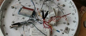
Power supplies
Bottom Circuit Board
Located on the bottom half of the open housing, the second circuit board provides voltage regulation and device control. This is a single sided board with a few jumpers and components on both sides. The solder side is varnished to protect small surface mount components.
Small surface mount components
The AC power supplied to this board is divided into two paths: a higher-power path that powers the induction coil, and a lower-power path that powers the control electronics.
120V is connected through a pair of terminal connectors. The 120V then passes through a 250V/20A fuse. At the input is a Thinking TVR 07241 varistor to protect the electronics.
Following further along a less low-power path, we encounter an AC-DC voltage converter, at the beginning of which there are four diodes that form a bridge rectifier. This converter is controlled by an STMicroelectronics VIPER12A and an EE13 core pulse transformer. This converter operates at a fixed frequency of 60 kHz.
Low power switching power supply
IGBT transistor in a high-power switching power supply
Power for high-power electronics also passes through a bridge rectifier, albeit with a larger heatsink. The rectified voltage is then sent to the two large inductors L1 and L2 and then smoothed by C2 and C3. Two IGBT transistors connected in parallel, Q1 and Q10, switch the voltage across the coil. These are Infineon IHW20N120R3 transistors, rated at 40 A at 1200 V.
Single-phase network 220 V
This case applies mainly to apartments in which the owner decided that during renovations or just because it is worth installing an induction hob instead of a classic gas stove. What does this have to do with repairs? Of course, this is not a necessary condition, but in most cases the 220 V network is not ready to accept such an energy-intensive consumer, and it will be necessary to lay an additional cable from the switchgear to the induction hob and slightly modernize the distribution board.
Connecting an induction hob in a single-phase installation without prior preparation and checking the existing network is risky! An induction hob is not a refrigerator! Induction consumes a lot of electricity, more than any device in the apartment. You need to be sure that the power grid will be able to withstand such a load.
- Firstly, for induction, a separate cable must be used coming from the distribution device, intended only for this purpose.
- Secondly, the cable must have a cross-section adapted to the power of the board.
The instructions for some stoves state that the protection must be at least 30 A and the cable with a cross-section of 4 mm2. However, to improve wiring safety, it is better to use 25 A protection (such as a B25 switch).
Let's move on to the options for connecting the stove. The following diagrams are prepared based on the connection methods for individual models selected by the manufacturer. Always check the instructions before connecting your model.
Connecting the plate to the outgoing cable
In this case, the plate is a closed box from which a cable, most often 5-wire, is brought out. The most common are:
- Black and brown conductors - phase
- Blue and gray wires are neutral
- Yellow-green wire – protective
See examples of drawings from the instructions for the induction panel above.
When the power cord has an inappropriate cross-section
If the power cord has a cross-section of 2.5 mm2, it must be protected using a switch with a lower current rating, such as B16. In this case, it is worth buying an induction hob with limited energy consumption so that the maximum current switch does not trip when using 3 or 4 heating fields.
There are opinions that each induction hob has a controller that takes into account that the network is single-phase and does not allow half heating at full power or intelligently switches them if they are all working at once, that is, the consumption of 7.2 kW in a single-phase installation is only on paper.
However, not every induction cooker, when you connect it to single-phase weak wiring, automatically reduces energy consumption. If the manufacturer does not include such information in the instruction manual, it should be assumed that if 4 burners are turned to the maximum heat level, the induction hob will consume approximately 7200 W of energy in total.
Useful: Connecting an ultrasonic sensor to Arduino
Connecting a plate with clamps instead of wires
If the stove model has a terminal with terminals located at the bottom instead of wires, it can be directly connected to the junction box.
Types of breakdowns and ways to fix them
Due to the high reliability of electronic components, control elements rarely fail. Most often, the consumer encounters minor minor faults, which are represented by the following list:
- insufficient heating power;
- one of the burners does not turn on;
- a couple of burners do not work;
- the stove does not turn on or turns off by itself;
- the panel hums during operation, etc.
These malfunctions can sometimes occur due to improper operation of the electric stove.
Incorrect operation
Insufficient heating power of the burners can occur when the cookware is placed incorrectly on the hob, or when its diameter is less than 70% of the heating zone. The problem can also be caused by a loose fit of the bottom of the pan (frying pan or kettle) to the surface of the stove.
One or more burners do not heat due to incorrect activation sequence. According to the operating instructions, to turn on the panel, you first need to select the desired burner using sensors, and then set the required power level. In addition, cookware placed on the heating element must have ferromagnetic properties.
An induction surface or stove may make noise when the heater power is set too high, if the cookware is installed with a thin bottom or vice versa - made of several layers of metal, as well as due to the small dimensions of the kitchen utensils, which are placed on a large burner.
Heaters turn off spontaneously for the following reasons:
- if within 10 sec. from the moment of switching on, the user has not performed a single action on the control panel (selecting a cooking place, setting power, etc.);
- when the burners operate continuously for more than 2 hours;
- as a result of the operation of the timer on which the shutdown time was set.
Overheating of the hob can be caused by contamination or moisture.
Technical breakdowns
First you need to make sure that the occurrence of malfunctions is not the result of a gross user error that can be eliminated without resorting to repairs. And only then should you begin to search for the reasons that caused this or that malfunction. It must be remembered that before starting repairs of induction cookers and hobs, you need to unplug the power cord from the power outlet.
In many cases, malfunctions occur due to damage to the power cable. Therefore, any repair begins with checking its integrity. Initially, the condition of the cord should be checked visually, and then using a multimeter (tester). After making sure that the cable is in good condition, you can move on - check the functionality of the fuses and the condition of the contacts in the terminal boxes.
Identified defects must be eliminated (replace fuses, clean contacts, replace parts that are broken, etc.). And the decision to further continue independent repairs should be made only after launching a self-testing (self-diagnosis) program for the electric stove or hob.
Three-phase network 380 V
The most common solution used by manufacturers is to power the stove not with three, but with two phases. The reason is simple. An induction cooker is not a three-phase motor, where strictly 3 lines are needed. An induction hob is a system of 4 independent elements - heating fields.
The easiest way is to separate them so that two fields are powered from one phase and two from the other. For example, it might look like this:
- Field 1 – power 1800 W (phase L1)
- Field 2 – power 1800 W (phase L1)
- Field 3 – power 1400 W (phase L2)
- Field 4 – power 2200 W (phase L2)
The fields are divided so that two average values are supplied from one phase and the smallest and largest from the second phase. Both of them have ~3600W of power, which is about 16A of current.
Connecting a plate with wires (2 phases)
As you can see, in this case the gray power cord (L3) is not used. Examples of drawings from the induction hob instructions related to the above diagram:
The unused cable is a gray power cord that should be insulated.
Connecting the board with terminals (2 phases)
Sometimes in such cases it is necessary to establish a connection between N terminals on the board. It can be made in the form of a plate that comes with the stove and only requires tightening the wires with a screwdriver.
Connecting a plate with terminals instead of a cable (2 phases) is a solution often used in practice
This is what a connection diagram looks like, which is often used in real conditions. During the installation phase, an induction hob is used, so the cable from the switchgear ends in the installation box. If the induction cooker comes with a cable, it is output to the box; if not, you need to buy an OMY cable (ShVVP) 5 x 2.5.
In addition, the unused phase (in this case L3) is also connected to the oven to ensure even loading of the phase. The oven can also be supplied with a separate 3 x 2.5 cable from the switchgear (and connects to a single phase overcurrent switch). Then, if one of the devices is damaged, the other can be used without any problems.
Complete three phase network for connection
If you are still in the construction stage of your home, you will most likely not have a selected induction cooktop model during the electrical wiring installation. But it’s worth thinking about one thing in advance. Will it be a standard 7.2 kW stove or a higher power 10 kW. Higher capacity stoves are larger and require all three phases to be supplied.
In this case, the possibility of powering the furnace from the distribution box is excluded. You run a separate wire from a switchgear designed just for the induction cooker.
Restoring functionality
Single-burner induction hobs are increasingly being used in private residences and apartments. Electrical diagrams allow home DIYers to carry out the necessary repairs themselves. The first step is always to disconnect the product from the power supply. Only after this the decorative surface is dismantled to gain full access to the parts. Any traces of soot, changes in the traditional colors of elements, or signs of melting should cause concern.
Experts recommend preparing a diagram of an electric induction cooker in advance, since in this case all repair work will be completed much faster. You can download the required document on the official website of the product manufacturer. Using a multimeter you need to check the fuse box, cable and the contacts themselves. Be sure to inspect the spirals of the induction coils. There should be no cracks on the products, as well as contact between the turns. It is necessary to test the serviceability of the connecting wiring. The circuits are checked with a multimeter. It is necessary to carefully remove the problematic burner along with the generator board. The master will have to carefully examine the element base. Burnt radio components are visible to the naked eye. When a problem is detected, the failed parts need to be replaced. In this case, a diagram of an induction cooker will help. It is not so difficult to perform all the necessary manipulations with your own hands if you prepare the necessary tools in advance.
What connectors to use for the oven
To save as much space as possible and not fill the box with wires, it should be at least 10x10x5 cm. There is no need to save space because the unit will be covered by kitchen furniture.
To prevent the wires from being pulled, it is better to make loops at the ends of the wires (picture on the right) when connecting. As you can see in the above pictures, a special terminal block with screw terminals is used for three-phase conductors, neutral conductor and protective conductor. Its advantage is that after opening the lid you can see everything connected to it.
The rated current, that is, the maximum current that can flow through each terminal for a long time, for a single-phase network should be at least 32 A.
The use of spring terminal blocks for three-phase systems is not a problem and can be used quite well. They have a rated current of 24 A. But in a single-phase network, this is usually not enough to reliably connect an induction hob - it is better to use screw terminals.
User Interface Electronics
User Interface Circuit Board
These electronics allow the user to control the cooktop. The user interface electronics consists of a printed circuit board with all the user interface elements located on it. This board contains seven 5mm red LEDs, six tactile buttons and a seven-segment display. The board has pads for two additional buttons and two more LEDs, but they are empty.
1628 LED Driver
On the back of the board there is a “1628” LED driver. The 1628 LED driver is made by several companies and can do much more than just drive LEDs. The 1628 converts serial data to control individual LEDs and allows button scanning. This driver is housed in a SOP 28 package and is soldered to the back of a single-layer PCB.
User Interface Printed Circuit Board. Side with components
The PCB has several other passive elements located on top. These components perform logic level conversion using voltage dividers and help filter signals.
Components
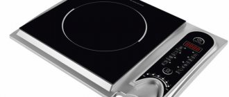
The panel can be connected through a socket with grounding or without a socket. We got ready to cook, turned on the electric stove, and poured liquid into the pan. Hansa This manufacturer offers a wide selection of cookers, including induction-type products.
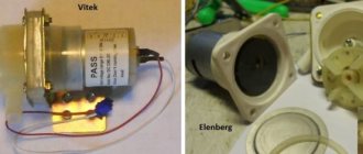
On the radiator there is a diode bridge and an IGBT transistor. The situation also repeated itself.
Check the power switch, fuse, and the quality of the connection between the control unit and the power board and touch panel; Cooling fan failure. After all, I repeat, there are electronics and not three parts.