Computer power supply (PSU)
is an independent pulse electronic device designed to convert AC voltage into a series of DC voltages (+3.3 / +5 / +12 and -12) to power the motherboard, video card, hard drive and other computer units.
Before you start repairing the computer power supply, you need to make sure that it is faulty, since the inability to start the computer may be due to other reasons.
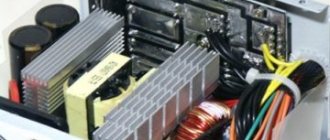
Photo of the appearance of a classic ATX power supply for a stationary computer (desktop).
Where is the power supply located in the system unit and how to disassemble it
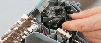
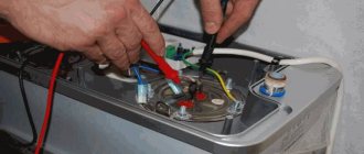
To gain access to the computer's power supply, you must first remove the left side wall from the system unit by unscrewing two screws on the rear wall on the side where the connectors are located.
To remove the power supply from the system unit case, you need to unscrew the four screws marked in the photo. To conduct an external inspection of the power supply, it is enough to disconnect from the computer units only those wires that interfere with the installation of the power supply on the edge of the system unit case.
Having placed the power supply on the corner of the system unit, you need to unscrew the four screws located on top, in the pink photo. Often one or two screws are hidden under a sticker, and to find the screw you need to peel it off or pierce it with the tip of a screwdriver. There are also stickers on the sides that make it difficult to remove the cover; they need to be cut along the line of mating parts of the power supply housing.
After the cover from the power supply unit is removed, be sure to remove all dust with a vacuum cleaner. It is one of the main reasons for the failure of radio components, since by covering them with a thick layer, it reduces the heat transfer from the parts, they overheat and, working in difficult conditions, fail faster.
For reliable operation of the computer, it is necessary to remove dust from the system unit and power supply, and also check the operation of coolers at least once a year.
Test method (instructions)
After the power supply is removed from the system unit and disassembled, first of all, it is necessary to inspect it to detect damaged elements (darkening, changed color, loss of integrity). Note that in most cases, replacing the burnt part will not solve the problem; you will need to check the piping.
Visual inspection allows you to detect “burnt out” radioelements
If none are found, proceed to the following algorithm of actions:
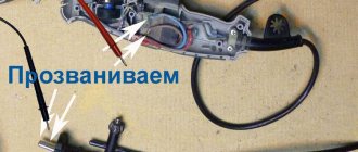
- check the fuse. You should not trust a visual inspection, but it is better to use a multimeter in dial mode. The reason why the fuse has blown may be a breakdown of the diode bridge, a key transistor, or a malfunction of the unit responsible for the standby mode;
On-board fuse
- checking the disk thermistor. Its resistance should not exceed 10 Ohms; if it is faulty, we strongly advise against installing a jumper instead. The pulse current that occurs during the charging of capacitors installed at the input can cause breakdown of the diode bridge;
Disc thermistor (indicated in red)
- We test diodes or a diode bridge on the output rectifier; there should be no open circuit or short circuit in them. If a malfunction is detected, the capacitors and key transistors installed at the input should be checked. The alternating voltage supplied to them as a result of the breakdown of the bridge, with a high probability, caused these radio components to fail;
Rectifier diodes (circled in red)
- checking electrolytic type input capacitors begins with inspection. The geometry of the body of these parts must not be violated. After this, the capacitance is measured. It is considered normal if it is not less than declared, and the discrepancy between the two capacitors is within 5%. Also, varistors and equalizing resistances sealed parallel to the input electrolytes must be checked;
Input electrolytes (indicated in red)
- testing of key (power) transistors. Using a multimeter, we check the base-emitter and base-collector junctions (the technique is the same as when checking diodes).
The placement of power transistors is shown
If a faulty transistor is found, then before soldering in a new one, it is necessary to test its entire wiring, consisting of diodes, low-resistance resistances and electrolytic capacitors. We recommend replacing the latter with new ones that have a larger capacity. Good results are obtained by shunting electrolytes using 0.1 μF ceramic capacitors;
- Checking output diode assemblies (Schottky diodes) using a multimeter, as practice shows, the most typical malfunction for them is a short circuit;
Diode assemblies marked on the board
- checking electrolytic type output capacitors. As a rule, their malfunction can be detected by visual inspection. It manifests itself in the form of changes in the geometry of the radio component housing, as well as traces of electrolyte leakage.
It is not uncommon for an apparently normal capacitor to turn out to be unusable when tested. Therefore, it is better to test them with a multimeter that has a capacitance measurement function, or use a special device for this.
Video: correct repair of an ATX power supply. https://www.youtube.com/watch?v=AAMU8R36qyE
Note that non-working output capacitors are the most common fault in computer power supplies. In 80% of cases, after replacing them, the performance of the power supply is restored;
Capacitors with broken housing geometry
- The resistance between the outputs and zero is measured; for +5, +12, -5 and -12 volts this indicator should be in the range from 100 to 250 Ohms, and for +3.3 V in the range of 5-15 Ohms.
Block diagram of the power supply unit of an ATX computer
A computer power supply is a rather complex electronic device and repairing it requires deep knowledge of radio engineering and the availability of expensive equipment, but, nevertheless, 80% of failures can be eliminated independently, having the skills of soldering, working with a screwdriver and knowing the block diagram of the power source.
Almost all computer power supplies are made according to the block diagram below. I have shown the electronic components in the diagram only those that most often fail and are available for non-professionals to replace on their own. When repairing an ATX power supply, you will definitely need color coding of the wires coming out of it.
The supply voltage is supplied via a power cord through a plug-in connection to the power supply board. The first element of protection is fuse Pr1, usually rated at 5 A. But depending on the power of the source, it may have a different rating. Capacitors C1-C4 and inductor L1 form a filter that serves to suppress common-mode and differential noise that arises from the operation of the power supply itself and can come from the network.
Surge filters assembled according to this scheme are required to be installed in all products in which the power supply is made without a power transformer, in televisions, VCRs, printers, scanners, etc. Maximum efficiency of the filter is possible only when connected to a network with a ground wire. Unfortunately, cheap Chinese computer power supplies often do not have filter elements.
Here is an example of this: the capacitors are not installed, and instead of the inductor, jumpers are soldered. If you are repairing a power supply and find that filter elements are missing, it is advisable to install them.
Here is a photo of a high-quality computer power supply, as you can see, filter capacitors and a noise suppression choke are installed on the board.
To protect the power supply circuit from supply voltage surges, expensive models install varistors (Z1-Z3), pictured on the right side in blue. Their operating principle is simple. At normal network voltage, the resistance of the varistor is very high and does not affect the operation of the circuit. If the voltage in the network increases above the permissible level, the resistance of the varistor sharply decreases, which leads to the fuse blowing, and not to the failure of expensive electronics.
To repair a failed unit due to overvoltage, it will be enough to simply replace the varistor and fuse. If you don’t have a varistor at hand, then you can only get by by replacing the fuse; the computer will work normally. But at the first opportunity, in order not to take risks, you need to install a varistor in the board.
Some models of power supplies provide the ability to switch to operate at a supply voltage of 115 V; in this case, the contacts of switch SW1 must be closed.
For a smooth charge of electrolytic capacitors C5-C6, connected immediately after the rectifier bridge VD1-VD4, an RT thermistor with a negative TCR is sometimes installed. In a cold state, the resistance of the thermistor is a few ohms; when current passes through it, the thermistor heats up and its resistance decreases by 20-50 times.
To be able to turn on the computer remotely, the power supply has an independent, additional low-power power source that is always on, even if the computer is turned off, but the electrical plug is not removed from the socket. It generates a voltage of +5 B_SB and is built according to the circuit of a transformer self-oscillating blocking oscillator on a single transistor, powered from a rectified voltage by diodes VD1-VD4. This is one of the most unreliable components of the power supply and is difficult to repair.
The voltages required for the operation of the motherboard and other devices of the system unit, when leaving the voltage generation unit, are filtered from interference by chokes and electrolytic capacitors and then supplied to consumption sources through wires with connectors. The cooler, which cools the power supply itself, is powered, in older power supply models from a voltage of minus 12 V, in modern ones from a voltage of +12 V.
Repairing the power supply step by step - checking and replacing capacitors
The problem of excessive standby voltage is a banal increase in the ESR of electrolytic capacitors in the power circuits. We look for these capacitors in the diagram and check them. We will need an ESR meter.
I check the first capacitor in the standby power supply circuit.
ESR is within normal limits. Let's check the second one.
We wait for a value to appear on the multimeter screen, but nothing changes.
At least one of the culprits of the problem has been found. We resolder the capacitor with exactly the same nominal value and operating voltage, taken from the donor power supply board. Let's take a closer look here.
So, turn on the power supply and measure the voltage at the control room again. Having learned from bitter experience, we are no longer in a hurry to install a new protective zener diode and measure the voltage at the control room, relative to the ground. The voltage is 12 volts and a high-frequency whistle is heard.
Next, we tried changing a 10 µF capacitor. This is one of the typical malfunctions of this power supply.
We measure ESR on the capacitor.
The result is the same as in the first case: the device goes off scale.
Some say, why collect some devices, such as swollen non-working capacitors, you can see that they are swollen or have opened up like a rose.
On the one hand, we agree with this. But this only applies to large capacitors. Capacitors of relatively small values do not swell. There are no notches in their upper part through which they could open. Therefore, it is simply impossible to determine their performance visually. All that remains is to replace them with ones that are known to work.
So, we found the second capacitor we needed and measured its ESR just in case. It turned out to be normal. After soldering the second capacitor into the board, turn on the power supply using the key switch and measure the standby voltage. What was required was 5.02 volts.
We measure all other voltages at the power supply connector. Everything corresponds to the norm. Operating voltage deviations are less than 5%. It remains to solder a 6.3 Volt zener diode.
By the way, we thought for a long time why the zener diode is exactly 6.3 Volts when the voltage on duty is +5 Volts? It would be more logical to set it to 5.5 volts or similar if it was used to stabilize the voltage on the duty room. Most likely, this zener diode is installed here as a protective one, so that if the voltage on the control panel increases above 6.3 Volts, it will burn out and short-circuit the control panel circuit, thereby turning off the power supply and saving the motherboard from burning.
The second function of this zener diode is most likely to protect the PWM controller from receiving too much voltage. Since the control room is connected to the power supply of the microcircuit through a fairly low-resistance resistor, almost the same voltage is supplied to pin 20 of the power supply of the PWM microcircuit as on the control room.
ATX computer power supply repair
Attention! To avoid damaging the computer, uncoupling and connecting the connectors of the power supply and other components inside the system unit must be performed only after completely disconnecting the computer from the power supply.
(remove the plug from the socket or turn off the switch in the “Pilot”).
The first thing that needs to be done is to check the presence of voltage in the outlet and the serviceability of the “Pilot” type extension cord by the glow of its switch key. Next, you need to check that the computer’s power cord is securely inserted into the “Pilot” and the system unit and that the switch (if any) on the back wall of the system unit is turned on.
How to find a power supply fault by pressing the “Start” button
If power is supplied to the computer, then in the next step you need to look at the power supply cooler (visible behind the grille on the back wall of the system unit) and press the “Start” button of the computer. If the cooler blades move even a little, it means that the filter, fuse, diode bridge and capacitors on the left side of the block diagram are working, as well as the independent low-power power supply +5 B_SB.
In some PSU models, the cooler is on the flat side and to see it, you need to remove the left side wall of the system unit.
Turning at a small angle and stopping the cooler impeller when you press the “Start” button indicates that output voltages momentarily appear at the output of the power supply unit, after which the protection is triggered, stopping the operation of the power supply unit. The protection is configured in such a way that if the current value for one of the output voltages exceeds a specified threshold, then all voltages are turned off.
The cause of an overload is usually a short circuit in the low-voltage circuits of the power supply itself or in one of the computer units. A short circuit usually occurs when there is a breakdown in semiconductor devices or insulation in capacitors.
To determine the node in which a short circuit has occurred, you need to disconnect all power supply connectors from the computer units, leaving only those connected to the motherboard. Then connect the computer to the power supply and press the “Start” button. If the cooler in the power supply was spinning, it means that one of the disconnected nodes is faulty. To determine the faulty node, you need to connect them in series to the power supply.
If the power supply connected only to the motherboard does not work, you should continue troubleshooting and determine which of these devices is faulty.
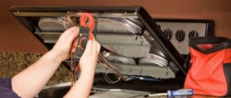
Checking the computer power supply by measuring the resistance value of the output circuits
When repairing a power supply, some types of its malfunction can be determined by measuring with an ohmmeter the resistance value between the common black GND wire and the remaining contacts of the output connectors.
Before starting measurements, the power supply must be disconnected from the power supply, and all its connectors must be disconnected from the system unit components. The multimeter or tester must be turned on in resistance measurement mode and select a limit of 200 Ohms. Connect the common wire of the device to the connector contact to which the black wire goes. The end of the second probe touches the contacts in turn, in accordance with the table.
| Table of resistance between the terminals of the ATX power supply | ||||||
| Output voltage, V | +3,3 | +5,0 | +12,0 | -12,0 | +5.0 SB | GND |
| Wire color | orange | red | yellow | blue | violet | black |
| Resistance should be more than ohm | 6,5 | 20 | 130 | 98 | 46 | — |
| Most probable values, Ohm | 7, 15, 32, ∞ | 50, 96, 200, ∞ | 136, 264, ∞ | 98,195, ∞ | 46, 98, ∞ | — |
The table shows generalized data obtained as a result of measuring the resistance value of the output circuits of 20 serviceable power supply units of computers of different capacities, manufacturers and years of manufacture.
To be able to connect a power supply for testing without load, load resistors are installed inside the unit at some outputs, the value of which depends on the power of the power supply and the manufacturer’s decision. Therefore, the measured resistance can fluctuate over a wide range, but should not be below the permissible value.
If a load resistor is not installed in the circuit, then the ohmmeter readings will vary from a small value to infinity. This is due to the charging of the filter electrolytic capacitor from the ohmmeter and indicates that the capacitor is working. If you swap the probes, a similar picture will be observed. If the resistance is high and does not change, then the capacitor may be broken.
A resistance less than the permissible value indicates the presence of a short circuit, which may be caused by an insulation breakdown in an electrolytic capacitor or a rectifying diode. To determine the faulty part, you will have to open the power supply and unsolder one end of the filter choke of this circuit from the circuit. Next, check the resistance before and after the throttle. If after it, then there is a short circuit in the capacitor, wires, between the tracks of the printed circuit board, and if before it, then the rectifier diode is broken.
Troubleshooting the power supply by external inspection
Initially, you should carefully inspect all the parts, paying special attention to the integrity of the geometry of the electrolytic capacitors. As a rule, due to severe temperature conditions, electrolytic capacitors fail most often. About 50% of power supply failures are due to faulty capacitors. Often, swelling of capacitors is a consequence of poor performance of the cooler. The cooler bearings run out of lubrication and the speed drops. The cooling efficiency of the power supply parts decreases and they overheat. Therefore, at the first sign of a malfunction of the power supply cooler, additional acoustic noise usually appears; you need to clean the cooler from dust and lubricate it.
If the capacitor body is swollen or traces of leaked electrolyte are visible, then the failure of the capacitor is obvious and it should be replaced with a serviceable one. The capacitor swells in the event of an insulation breakdown. But it happens that there are no external signs of failure, but the level of output voltage ripple is greater. In such cases, the capacitor is faulty due to lack of contact between its terminal and the plate inside it, as they say, the capacitor is broken. You can check the capacitor for open circuit using any tester in resistance measurement mode. The technology for testing capacitors is presented in the website article “Measuring Resistance”.
Next, the remaining elements, fuse, resistors and semiconductor devices are inspected. Inside the fuse, a thin metal wire should run along the center, sometimes with a thickening in the middle. If the wire is not visible, then most likely it has burned out. To accurately check the fuse, you need to test it with an ohmmeter. If the fuse is blown, it must be replaced with a new one or repaired. Before making a replacement, to check the power supply, you can not solder the blown fuse from the board, but solder a copper wire with a diameter of 0.18 mm to its terminals. If the wiring does not burn out when you turn on the power supply to the network, then it makes sense to replace the fuse with a working one.
How to check the serviceability of the power supply by closing the PG and GND contacts
If the motherboard can only be checked by connecting it to a known-good power supply, then the power supply can be checked separately using a load block or started by connecting the +5 V PG and GND contacts to each other.
From the power supply to the motherboard, supply voltages are supplied using a 20 or 24 pin connector and a 4 or 6 pin connector. For reliability, the connectors have latches. In order to remove the connectors from the motherboard, you need to press the latch upward with your finger at the same time, applying quite a lot of force, rocking from side to side, and pull out the mating part.
Next, you need to short-circuit the two terminals in the connector removed from the motherboard with each other, using a piece of wire or perhaps a metal paper clip. The wires are located on the latch side. In the photographs, the location of the jumper is indicated in yellow.
If the connector has 20 pins
, then you need to connect pin
14
(green wire, in some power supplies it may be gray, POWER ON) and pin
15
(black wire, GND).
If the connector has 24 pins
, then you need to connect pin
16
(green, in some power supplies the wire may be gray, POWER ON) and pin
17
(black GND wire).
If the impeller in the power supply cooler rotates, then the ATX power supply can be considered operational, and, therefore, the reason for the computer not working is in other units. But such a check does not guarantee stable operation of the computer as a whole, since deviations in output voltages may be greater than permissible.
Checking the computer's power supply by measuring voltages and ripple levels
After repairing the power supply or in case of unstable operation of the computer, in order to be completely sure that the power supply is in good working order, it is necessary to connect it to the load block and measure the level of output voltages and the ripple range. The deviation of voltage values and ripple amplitude at the output of the power supply should not exceed the values given in the table.
You can do without a load block by measuring the voltage and ripple level directly at the terminals of the power supply connectors in a running computer.
| Table of output voltages and ripple range of ATX power supply | |||||||
| Output voltage, V | +3,3 | +5,0 | +12,0 | -12,0 | +5.0 SB | +5.0 PG | GND |
| Wire color | orange | red | yellow | blue | violet | grey | black |
| Permissible deviation, % | ±5 | ±5 | ±5 | ±10 | ±5 | – | – |
| Permissible minimum voltage | +3,14 | +4,75 | +11,40 | -10,80 | +4,75 | +3,00 | – |
| Permissible maximum voltage | +3,46 | +5,25 | +12,60 | -13,20 | +5,25 | +6,00 | – |
| Ripple range no more than, mV | 50 | 50 | 120 | 120 | 120 | 120 | – |
When measuring voltages with a multimeter, the “negative” end of the probe is connected to the black wire (common), and the “positive” end to the desired connector contacts.
Voltage +5 V SB (Stand-by), purple wire – produces an independent low-power power supply built into the power supply unit, made on one field-effect transistor and transformer. This voltage ensures the computer operates in standby mode and serves only to start the power supply. When the computer is running, the presence or absence of +5 V SB voltage does not matter. Thanks to +5 V SB, the computer can be started by pressing the “Start” button on the system unit or remotely, for example, from an uninterruptible power supply unit in the event of a prolonged absence of 220 V supply voltage.
Voltage +5 V PG (Power Good) - appears on the gray wire of the power supply unit after 0.1-0.5 seconds if it is in good condition after self-testing and serves as an enabling signal for the operation of the motherboard.
A voltage of minus 12 V (blue wire) is only needed to power the RS-232 interface, which is absent in modern computers. Therefore, power supplies of the latest models may not have this voltage.
How to replace a fuse in a computer's power supply
Typically, computer power supplies are equipped with a tubular glass fuse designed for a protection current of 6.3 A. For reliability and compactness, the fuse is soldered directly into the printed circuit board. For this purpose, special fuses are used that have terminals for sealing. The fuse is usually installed in a horizontal position next to the surge protector and is easy to spot by its appearance.
But sometimes there are power supplies in which the fuse is installed in a vertical position and a heat-shrinkable tube is put on it, as in the photo above. As a result, it is difficult to detect. But the inscription on the printed circuit board next to the fuse helps: F1 - this is how the fuse is designated on electrical circuits. Next to the fuse, the current for which it is rated may also be indicated; on the presented board, a current of 6.3 A is indicated.
When repairing the power supply and checking the vertically installed fuse using a multimeter, it was discovered that it was broken. After desoldering the fuse and removing the heat shrink tubing, it became obvious that it had blown. The inside of the glass tube was completely covered with a black coating from the burnt wire.
Fuses with wire leads are rare, but they can be successfully replaced with ordinary 6.3 ampere fuses by soldering single-core pieces of copper wire with a diameter of 0.5-0.7 mm to the ends of the cups.
All that remains is to solder the prepared fuse into the printed circuit board of the power supply and check its functionality.
If, when the power supply is turned on, the fuse burns out again, it means that there is a failure of other radio elements, usually a breakdown of the transitions in the key transistors. Repairing a power supply with such a fault requires high qualifications and is not economically feasible. Replacing a fuse designed for a higher protection current than 6.3 A will not lead to a positive result. The fuse will still blow.
Searching for faulty electrolytic capacitors in the power supply
Very often, a power supply failure, and as a result, unstable operation of the computer as a whole, occurs due to swelling of the electrolytic capacitor housings. To protect against explosion, notches are made at the end of electrolytic capacitors. As the pressure inside the capacitor increases, the housing swells or ruptures at the notch, and by this sign it is easy to find a failed capacitor. The main reason for the failure of capacitors is their overheating due to a malfunction of the cooler or exceeding the permissible voltage.
The photo shows that the capacitor on the left side has a flat end, while the end on the right is swollen, with traces of leaking electrolyte. This capacitor has failed and must be replaced. In the power supply, electrolytic capacitors on the +5 V power bus usually fail, since they are installed with a small voltage margin, only 6.3 V. I have encountered cases when all the capacitors in the power supply on the +5 V circuit were swollen.
When replacing capacitors on a 5 V power supply circuit, I recommend installing capacitors that are designed for a voltage of at least 10 V. The higher the voltage the capacitor is designed for, the better, the main thing is that the dimensions fit into the installation location. If a capacitor with a higher voltage does not fit due to its size, you can install a capacitor with a smaller capacity, but designed for a higher voltage. All the same, the capacity of the capacitors installed at the factory has a large reserve and such a replacement will not worsen the performance of the power supply and the computer as a whole.
The larger the capacity of the installed capacitor, the better. So when replacing, it is better to choose a capacitor designed for a higher voltage and capacity than that of the failed one. Replacing a failed capacitor in a power supply is not difficult if you have the skills to work with a soldering iron. The article on the website “How to solder with a soldering iron” is devoted to soldering techniques.
There is no point in replacing electrolytic capacitors in the power supply if they are all swollen. This means that the output voltage stabilization circuit has failed, and a voltage exceeding the permissible value was applied to the capacitors. Such a power supply can be repaired only with professional education and measuring instruments, but such repairs are not economically feasible.
The main thing when repairing a power supply is not to forget that electrolytic capacitors have polarity. On the negative terminal side of the capacitor body there is a marking in the form of a wide light vertical stripe, as shown in the photo above. On the printed circuit board, the hole for the negative terminal of the capacitor is located in the marking area of the white (black) semicircle, or the hole for the positive terminal is indicated by a “+” sign.
Checking the group stabilization choke BP ATX
If you suddenly smell something burning from the computer system unit, then one of the reasons may be overheating of the group stabilization choke in the power supply unit or a burnt winding of one of the coolers. The computer usually continues to work normally. If, after opening the system unit and inspecting it, all coolers rotate, then the throttle is faulty. The computer must be turned off immediately and repaired.
The photo shows a computer power supply with the cover removed, in the center of which you can see the inductor, covered with green insulation, burnt on top. When I connected this power supply to the load and applied supply voltage to it, after a couple of minutes a thin stream of smoke came out of the inductor. The check showed that all output voltages within the tolerance and the ripple range do not exceed the permissible value.
The current of all voltages supplying the computer passes through the inductor and it is obvious that there has been a violation of the insulation of the wires of the windings as a result of which they short-circuited among themselves.
The windings can be rewinded onto the same core, but as a result of strong heating, the magnetodielectric of the core may lose its quality factor; as a result, due to high Foucault currents, it will heat up even with intact windings. Therefore, I recommend installing a new throttle. If there is no analogue, then you need to count the turns of the windings, winding them on the burnt inductor, and wind them with an insulated wire of the same cross-section on a new core. In this case, the direction of the windings must be observed.
Checking other power supply elements
Resistors and simple capacitors should not have any darkening or deposits. The cases of semiconductor devices must be intact, without chips or cracks. When making repairs yourself, it is advisable to replace only the elements shown in the block diagram. If the paint on the resistor has darkened, or the transistor has fallen apart, then there is no point in changing them, since most likely this is a consequence of the failure of other elements that cannot be detected without instruments. A darkened resistor body does not always indicate a malfunction. It is quite possible that only the paint has darkened, but the resistance of the resistor is normal.
Repairing a power supply - searching for a circuit and replacing the zener diode
Next, we look for a circuit for this power supply. On the Internet we found a Power Man 300 Watt circuit. The only differences in the circuit are the serial numbers of the radio components on the board. If you can analyze a printed circuit board for compliance with the diagram, this will not be a big problem.
Here is the circuit itself for Power Man 300W. Click on it to enlarge to full size.
As we can see, standby power (standby) is designated as +5VSB:
Directly from it goes a zener diode with a nominal value of 6.3 Volts to ground. And as you remember, a zener diode is the same diode, but connected in reverse in circuits. The zener diode uses the reverse branch of the current-voltage characteristic. If the zener diode were live, then our +5VSB wire would not short to ground. We assume that the zener diode has burned out and the PN junction is destroyed.
- See also how to assemble a simple tester for checking a zener diode
What happens when various radio components burn from a physical point of view? Firstly, their resistance changes. For resistors, it becomes infinite or, in other words, goes into a break. With capacitors it sometimes becomes very small or, in other words, goes into a short circuit. With semiconductors, both of these options are possible - both a short circuit and an open circuit.
In our case, we can check this in only one way, by unsoldering one or both legs of the zener diode, as the most likely culprit of the short circuit. Next, we will check whether the short circuit between the duty switch and ground has disappeared or not. Why is this happening?
Let's remember some simple tips:
- With a serial connection, the rule of more than more applies. In other words, the total resistance of the circuit is greater than the resistance of the larger resistor.
- With a parallel connection, the opposite rule works, less is less. In other words, the final resistance will be less than the resistance of the smaller resistor.
You can take arbitrary resistor resistance values, calculate them yourself and verify this. Let's try to think logically, if one of the resistances of parallel-connected radio components is equal to zero, what readings will we see on the multimeter screen? That's right, also equal to zero.
Until we fix this short circuit by desoldering one of the legs of the part that we consider to be problematic, we will not be able to determine which part we have a short circuit in. The point is that during audio testing, all parts connected in parallel to the part in a short circuit will ring short with the common wire!
We try to remove the zener diode. During the work, it simply fell apart in two.
We check whether the short circuit in the duty and ground circuits has been eliminated or not. Indeed, the short circuit has disappeared. We solder the new zener diode.
After turning on the power supply for the first time, the new zener diode began to emit smoke. Here we should remember one of the main rules of a repairman:
We cut the burnt zener diode with side cutters and turn on the power supply again. That’s right, the duty is too high: 8.5 Volts. Of course, at this moment we were worried about the PWM controller. However, after downloading the datasheet onto the chip, it was revealed that the maximum supply voltage for the PWM controller is 16 Volts.
Our assumption turned out to be incorrect; the problem is not with the zener diode. Go ahead.
Refinement of power supply
In conclusion, we will give some tips on improving the power supply, which will make its operation more stable:
- in many inexpensive units, manufacturers install two-amp rectifier diodes; they should be replaced with more powerful ones (4-8 amperes);
- Schottky diodes on the +5 and +3.3 volt channels can also be installed more powerful, but they must have an acceptable voltage, the same or greater;
- It is advisable to replace the output electrolytic capacitors with new ones with a capacity of 2200-3300 μF and a rated voltage of at least 25 volts;
- It happens that instead of a diode assembly, diodes soldered together are installed on the +12 volt channel; it is advisable to replace them with a Schottky diode MBR20100 or similar;
- if 1 µF capacitances are installed in the key transistors, replace them with 4.7-10 µF, designed for a voltage of 50 volts.
Such a minor modification will significantly extend the life of the computer power supply.
Very interesting to read:
Source: www.asutpp.ru
Design features and operating principle
Of the several methods of converting voltage to power electronic components, two that are most widespread can be identified:
- Analog, the main element of which is a step-down transformer, in addition to its main function, it also provides galvanic isolation.
- Impulse principle.
Let's look at how these two options differ.
PSU based on a power transformer
Simplified block diagram of an analog power supply
The next block performs two functions: it smoothes the voltage (a capacitor of appropriate capacity is used for this purpose) and stabilizes it. The latter is necessary so that the voltage does not “drop” when the load increases.
The given block diagram is greatly simplified; as a rule, a source of this type has an input filter and protective circuits, but this is not important for explaining the operation of the device.
All the disadvantages of the above option are directly or indirectly related to the main design element - the transformer. Firstly, its weight and dimensions limit miniaturization. In order not to be unfounded, we will use as an example a step-down transformer 220/12 V with a rated power of 250 W. The weight of such a unit is about 4 kilograms, dimensions 125x124x89 mm. You can imagine how much a laptop charger based on it would weigh.
Step-down transformer OSO-0.25 220/12
Secondly, the price of such devices is sometimes many times higher than the total cost of the other components.
Pulse devices
As can be seen from the block diagram shown in Figure 3, the operating principle of these devices differs significantly from analog converters, primarily in the absence of an input step-down transformer.
Figure 3. Block diagram of a switching power supply
Let's consider the operating algorithm of such a source:
Now, as promised, let’s look at the operating principle of the main element of this device – the inverter.
Here we will talk about switching power supplies (UPS), which are the most widely used today and are successfully used in all modern radio-electronic devices.
Here we will talk about switching power supplies (UPS), which are the most widely used today and are successfully used in all modern radio-electronic devices.
First of all, this article is dedicated to beginners in the repair of electronic equipment, so the material will be presented in a simplified form and will help to understand the basic principles of UPS operation.
The basic principle underlying the operation of the UPS is to convert the AC mains voltage (50 Hz) into an alternating high-frequency rectangular voltage, which is transformed to the required values, rectified and filtered.
The conversion is carried out using a powerful transistor operating in switch mode and a pulse transformer, together forming an RF converter circuit. As for the circuit design, there are two possible converter options: the first is made according to a pulse self-oscillator circuit (for example, this was used in the UPS of TVs 3 - 4 USST) and the second is with external control (used in most modern radio-electronic devices).
Since the converter frequency is usually selected from 18 to 50 kHz, the dimensions of the pulse transformer, and, consequently, the entire power supply, are quite compact, which is an important parameter for modern equipment.
The UPS uses two principles for implementing tracking circuits - “direct” and “indirect”. The method described above is called “direct”, since the feedback voltage is removed directly from the secondary rectifier. With “indirect” tracking, the feedback voltage is removed from the additional winding of the pulse transformer (Figure 2).
A decrease or increase in the voltage on winding W2 will lead to a change in voltage on winding W3, which is also applied through resistor R2 to pin 1 of the PWM controller.
Low frequency transformers lose a lot of energy and dissipate heat during transformations. In a UPS, maximum losses occur during transient switching processes. At other times, the transistors are stable, they are closed or open. Conditions have been created for energy conservation, efficiency reaches 98%.