Since I resumed my amateur radio activities, the thought of a high-quality and universal laboratory power supply has often crossed my mind. The power supply available and manufactured 20 years ago had only two output voltages - 9 and 12 volts with a current of about one Ampere. The remaining voltages necessary in practice had to be “twisted” by adding various voltage stabilizers, and to obtain voltages above 12 Volts, a transformer and various converters had to be used.
I got pretty tired of this situation and started looking for a lab diagram on the Internet to repeat. As it turned out, many of them are the same circuit on operational amplifiers, but in different variations. At the same time, on the forums, discussions of these schemes on the topic of their performance and parameters resembled the topic of dissertations. I didn’t want to repeat and spend money on dubious circuits, and during my next trip to Aliexpress I suddenly came across a linear power supply design kit with quite decent parameters: adjustable voltage from 0 to 30 Volts and current up to 3 Amps. The price of $7.5 made the process of independently purchasing components, designing and etching the board simply pointless. As a result, I received this set in the mail:
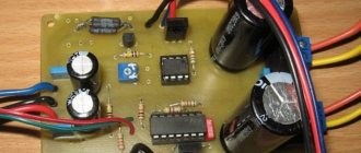
Regardless of the price of the set, I can call the quality of the board's manufacturing excellent. The kit even included two extra 0.1 uF capacitors. Bonus - they will come in handy)). All you need to do yourself is to “turn on the attention mode”, place the components in their places and solder them. The Chinese comrades took care to mix up what only a person who first learned about a battery and a light bulb could do - the board was silk-screened with the component values. The final result is a board like this:
Laboratory power supply specifications
- input voltage: 24 VAC;
- output voltage: 0 to 30 V (adjustable);
- output current: 2 mA - 3 A (adjustable);
- Output voltage ripple: less than 0.01%
- board size 84 x 85 mm;
- short circuit protection;
- protection for exceeding the set current value.
- When the set current is exceeded, the LED signals.
To obtain a complete unit, you should add only three components - a transformer with a voltage on the secondary winding of 24 volts at 220 volts at the input (an important point, which is discussed in detail below) and a current of 3.5-4 A, a radiator for the output transistor and a 24-volt cooler for cooling the radiator at high load current. By the way, I found a diagram of this power supply on the Internet:
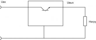
The main components of the circuit include:
- diode bridge and filter capacitor;
- control unit on transistors VT1 and VT2;
- the protection node on transistor VT3 turns off the output until the power supply to the operational amplifiers is normal
- fan power supply stabilizer on 7824 chip;
- A unit for forming the negative pole of the power supply of operational amplifiers is built on elements R16, R19, C6, C7, VD3, VD4, VD5. The presence of this node determines the power supply of the entire circuit with alternating current from the transformer;
- output capacitor C9 and protective diode VD9.
Separately, you need to dwell on some components used in the circuit:
- rectifier diodes 1N5408, selected end-to-end - maximum rectified current 3 Amperes. And although the diodes in the bridge work alternately, it would still not be superfluous to replace them with more powerful ones, for example, 5 A Schottky diodes;
- The fan power stabilizer on the 7824 chip was, in my opinion, not very well chosen - many radio amateurs will probably have 12-volt fans from computers on hand, but 24-volt coolers are much less common. I didn’t buy one, deciding to replace the 7824 with a 7812, but during testing the BP abandoned this idea. The fact is that with an input alternating voltage of 24 V, after the diode bridge and filter capacitor we get 24 * 1.41 = 33.84 Volts. The 7824 chip will do an excellent job of dissipating the extra 9.84 Volts, but the 7812 has a hard time dissipating 21.84 Volts into heat.
In addition, the input voltage for microcircuits 7805-7818 is regulated by the manufacturer at 35 Volts, for 7824 at 40 Volts. Thus, in the case of simply replacing 7824 with 7812, the latter will work on the edge. Here is a link to the datasheet.
Taking into account the above, I connected the available 12 Volt cooler through the 7812 stabilizer, powering it from the output of the standard 7824 stabilizer. Thus, the cooler’s power supply circuit turned out to be, although two-stage, reliable.
Operational amplifiers TL081, according to the datasheet, require bipolar power +/- 18 Volts - a total of 36 Volts and this is the maximum value. Recommended +/- 15.
And this is where the fun begins regarding the 24 Volt variable input voltage! If we take a transformer that, at 220 V at the input, produces 24 V at the output, then again after the bridge and filter capacitor we get 24 * 1.41 = 33.84 V.
Thus, only 2.16 Volts remain until the critical value is reached. If the voltage in the network increases to 230 Volts (and this happens in our network), we will remove 39.4 Volts of DC voltage from the filter capacitor, which will lead to the death of the operational amplifiers.
There are two ways out: either replace the operational amplifiers with others, with a higher permissible supply voltage, or reduce the number of turns in the secondary winding of the transformer. I took the second path, selecting the number of turns in the secondary winding at the level of 22-23 Volts at 220 V at the input. At the output, the power supply received 27.7 Volts, which suited me quite well.
As a heatsink for the D1047 transistor, I found a processor heatsink in the bins. I also attached a 7812 voltage stabilizer to it. Additionally, I installed a fan speed control board. A donor PC power supply shared it with me. The thermistor was secured between the fins of the radiator.
When the load current is up to 2.5 A, the fan rotates at medium speed; when the current increases to 3 A for a long time, the fan turns on at full power and reduces the temperature of the radiator.
DIY crafts for car enthusiasts
I present a circuit of a universal power supply that provides an adjustable output voltage from 0 to 30 V, with the ability to limit the current in the load within 0...3 A. Such power supplies are also commonly called laboratory ones.
Amateur radio practice and repair work related to electronics cannot be done without it. Someone might think, why? After all, there are LM317 and 338, where everything is much simpler... I’ll give an example. Let's say you are repairing a certain device, and after replacing failed parts, it's time to turn it on for the first time. The device is powered by, say, 12 V, consuming 300 mA. There is a possibility that after the repair, hidden defects remain, and if it is immediately connected to a 12 V power supply... there will be a surge in current and “bang”. And using the power supply in question, the switching method will be as follows: set the source to 12 V in idle mode, turn the current limiting knob to zero, connect the device and gradually increase the current, monitor the ammeter readings. Those. In this way, you can stop in time, seeing the upper limit of consumption and thereby avoid doing double repair work.
This power source can also be used as a charger, although you will have to manually monitor the charging current and disconnect the battery.
Simplicity and flexibility make this scheme truly universal. The declared voltage and current ranges can be easily changed in both directions, and without changing the circuit design, replacing transistors, sensor-resistor, input and reference voltage.
The input voltage for the circuit is provided by a 24 V transformer T1, a diode bridge VD1 and capacitors C1, C2. The voltage to power the quad op-amp DA1 LM324 is taken from the adjustable stabilizer VD2. With the indicated values of R2 and R3, it is equal to 10.7 V. The same voltage is used to form the adjustment values.
The power control element is a composite transistor VT1 of the pnp TIP126 structure. Depending on the resistance between its base and the common wire, it can be in different states: fully open - maximum voltage at the output, fully closed - zero at the output, and have a certain resistance, which ensures regulation.
The resistance between the base of VT1 and GND is resistor R7 and the npn junction of transistor VT2. The VT2 BD139 transistor is controlled by two independent circuits - adjusting the output voltage and limiting the current through the load.
The output voltage is adjusted by variable resistor R5, which together with R4 forms a voltage divider from the stabilizer VD2. This voltage is applied to the positive input (3) of DA1.1. The negative input (2) of DA1.1 receives voltage from the output of the circuit through the divider R9, R10. Whatever voltage value we apply to input 3 (by changing resistance R5), output (1) will open/close transistor VT2, and therefore change the resistance in the base circuit VT1 so that the values at inputs 3 and 2 are equal. This is how the output voltage is adjusted.
Adjusting the current limit The current sensor in the circuit is resistor R20, the voltage drop across which will depend on the current flowing through the load. This voltage drop comes to input 5 of DA1.2. Input 6 (negative) is connected via R18 to common. This OOS stage works as a voltage amplifier.
The limiting current is set by variable resistor R14, the voltage from which is supplied to input 9 of DA1.3. The positive input 10 receives voltage from DA1.2. In normal mode (no limitation), output 8 of DA1.3 has negative voltage values in mV, which are supplied through the cascade to DA1.4 to the VT3 base. In this mode, VT3 is locked and does not affect the operation of the voltage regulation circuit.
As soon as the voltage drop across R20 exceeds the specified threshold, the output of DA1.4 will become positive and VT3 will come into operation. Transition resistance VT3 connects the base of transistor VT2 to the common wire, thereby covering it, therefore, the output voltage will drop to the equilibrium value (depending on the magnitude of the overload) of the control cascades.
The printed circuit board is shown in the figure above. I did not indicate an ammeter and a voltmeter in the diagram, because With the current abundance of devices, it makes no sense to give specific recommendations. Variable resistors can be used soldered to the board or remotely. The radiator for cooling VT1 in passive mode must have an area of at least 400 cm2, because in “heavy” modes (low output voltage and high current), significant thermal energy is generated on it. As I already said, understanding the principle of operation of this circuit, it can be adapted to almost any voltage and current.
Popular;
- Low-power laboratory power supply based on LM317
- Making a circuit for a car radiator temperature sensor
Step-down module LM2596: characteristics and settings- Three power supplies for the car from 24 to 12 volts.
- Delay for turning on the low beam or DRL for 8-10 seconds, diagram
- Power supply with voltage and current regulation
- Charger from economy lamp
- Simple switching power supply based on IR2153
Digital indicator for the block
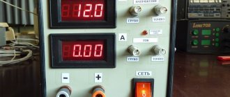
To visualize the voltage and current readings in the load, I used a DSN-VC288 voltammeter, which has the following characteristics:
- measuring range: 0-100V 0-10A;
- operating current: 20mA;
- measurement accuracy: 1%;
- display: 0.28" (Two colors: blue (voltage), red (current);
- minimum voltage measurement step: 0.1 V;
- minimum current measurement step: 0.01 A;
- operating temperature: from -15 to 70 °C;
- size: 47 x 28 x 16 mm;
- operating voltage required for operation of the ampere-voltmeter electronics: 4.5 – 30 V.
Considering the operating voltage range, there are two connection methods:
- If the source of the measured voltage operates in the range from 4.5 to 30 Volts , then the connection diagram looks like this:
- If the source of the measured voltage operates in the range 0-4.5 V or above 30 Volts , then up to 4.5 Volts the amperevoltmeter will not start, and at a voltage of more than 30 Volts it will simply fail, to avoid which you should use the following circuit:
In the case of this power supply, there is plenty to choose from for powering the ampere-voltmeter. The power supply has two stabilizers - 7824 and 7812. Before 7824, the wire length was shorter, so I powered the device from it, soldering the wire to the output of the microcircuit.
Scheme for converting an ATX power supply into an adjustable one
The diagram presented is a modification of the sample ATX power supply diagram, so it may be slightly different when it comes to the part containing the backup converter, the keys used or the values of some elements, so I have indicated the elements on the diagram by placing an "xx" next to those that should be changed or added.
The power supply is equipped with two 10 kOhm linear potentiometers, one for voltage regulation, the other for current limiting. The current is measured between the center tap of the transformer and ground using a 5 mΩ/2 W measuring resistor. The voltage across the sense resistor is negative with respect to ground, so it is supplied to TL494, the operational amplifier LM358 is only used to amplify the signal from the current control potentiometer. The added 36 kOhm resistor on pin 6 is only used to raise the inverter frequency from 30 kHz to about 45 kHz - without it the power supply will also work.
The first time I left the main transformer unchanged, turned on the power supply and when everything worked, I reconfigured the secondary winding connections. This operation is not necessary, but then the maximum output voltage can be safely raised to about 24 V. The transformer had 4 secondary windings on each side of 3 turns connected in parallel and one 4 turn winding added in series. The windings were separated and connected as in the diagram.
The inductor was used as is, first I removed all unnecessary windings from it and left only what was on the 12 V line. The inductor core is T106-26, at 30 turns it should have about 83 µH and a saturation current of 8.6.
The backup converter must remain unchanged and contain all the elements necessary for its proper operation, so it should not be changed, here the diagram is drawn up in a simplified form, only the place where the power for the controller and fan should be taken is indicated. The power supply was equipped with a conventional digital voltmeter module. The unit operates stably and is quite resistant to short circuits at the output terminals.
The AT type power supply can also be converted, only the transformer must be replaced or two FR107 diodes must be added to power the controller with a 6 turns (3+3) tap.
After converting the rectifier from the ATX power supply and removing the Standby mode, I converted it to AT and it also worked without problems. Current regulation also, even with the output wires shorted, increases the controller supply voltage to approximately 26-29 V.
Useful: 12 V charger with adjustable charging current
The AT power supply from the ATX, excluding the redundant converter, differs only in the way it supplies power to the controller (the power source is taken from the output rectifier before the inductor) and the additional 330k drive resistors between the collector and base of the main transistors.
Each ATX power supply can be safely adapted to 24V without touching the main transformer. The only thing that needs to be done is to remove unnecessary lines (in particular, 3.3 V) and solder the capacitors to a correspondingly higher voltage. It is also useful to increase the inverter frequency to approximately 40-50 kHz, then the risk of core saturation is reduced.
About the wires included in the kit
- The wires of the three-pin connector are thin and made of 26AWG wire - thicker is not needed here. Colored insulation is intuitive - red is the power supply for the module electronics, black is ground, yellow is the measuring wire;
- The wires of the two-contact connector are current measuring wires and are made of thick 18AWG wire.
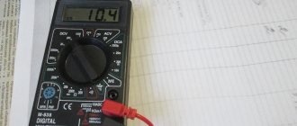
When connecting and comparing the readings with the multimeter readings, the discrepancies were 0.2 Volts. The manufacturer has provided trimmers on the board to calibrate voltage and current readings, which is a big plus. In some instances, non-zero ammeter readings are observed without load. It turned out that the problem can be solved by resetting the ammeter readings, as shown below:
The picture is from the Internet, so please forgive any grammatical errors in the captions. In general, we’ve finished with the circuit design - let’s move on to making the box...
BP forum
- LABORATORY PSU 1-24 V
- POWER SUPPLY FOR PRACTICUM
- PSU DIAGRAM 0-25 VOLTS 0-5 AMPERES
- SEQUENCER DIAGRAM
Power supply 0...30V/5A with digital indication of voltage and current
The described power supply is intended for use in an amateur radio laboratory. Despite the fact that many circuits of similar devices have been published in amateur radio literature, this power supply does not require specialized microcircuits and imported elements. Currently, the issue of purchasing microcircuits is still relevant in some regions; getting them is problematic. This power supply is an upgrade of the power supply described in (II). The power supply is assembled only from available parts.
Characteristics of the power supply: The output voltage is adjustable from 0 to 30 V. The output current is 5 A. The voltage drop at a current from 1 A to 6 A is negligible and is not reflected in the output indicators.
The power supply diagram is shown in Fig. 1 below
Rice. 1
This power supply contains three main units: internal network power unit VD 1- VD 4, C 1- C 7, DA 1, DA 2, overload and short circuit protection unit VS 1, R 1- R 4, VD 3 and the main unit – adjustable voltage stabilizer VT 2- VT 7, VD 4- VD 5, R 4- R 14, C 8.
A digital panel is also added to the power supply, i.e. indication block, which is shown in Fig. 5.
The internal network power supply unit is built according to a traditional scheme with a T1 network transformer.
The protection unit has no special features. The current sensor was designed for a current of 3A, but it can also be calculated for 5A. For a long time the power supply was operated with a current of 5A. There were no failures in its operation. Diode HL 1 indicates overcurrent or short circuit in the load.
The main unit is an adjustable voltage stabilizer of the compensation type. It contains an input differential stage on transistors VT 5, VT 7, two amplification stages on transistors VT 3 and VT 2, and a control transistor VT 1. Elements VT 4, VT 6, VD 4, VD 5, R 5 - R 8, R 10 form current stabilizers. Capacitor C8 prevents self-excitation of the unit. Because transistors VT 5 and VT 7 were not selected the same, then there is a certain “zero offset” of this stage, which is the minimum voltage of the power supply. Within small limits, it is regulated using a tuning resistor R 7 and, in the author’s version, reached approximately 47 m V at the output of the power supply. The output voltage is regulated by resistor R 13. The upper voltage limit is regulated by trimming resistor R 14.
Rice. 2
Construction and details. The power of transformer T1 must be at least 100 - 160 W, the current of winding II must be at least 4 - 6A. Winding current III – not less than 1...2A. The RS 602 diode assembly can be replaced with an RS 603 assembly or diodes rated for a current of 10A. The VD 2 diode bridge can be replaced with any of the KTs402 - KTs405 series, which are glued on the side of the printed tracks, mirroring the capacitor C1 and connected by flexible conductors to the VD 2 pads on the board. Transistor VT 1 should be installed on a heat sink with an area of at least 1500 cm 2. The radiator area is calculated by the formula S = 10 I n (U in. – U out.), where S is the surface area of the radiator (cm 2); I n – maximum current consumed by the load; U in. – input voltage (V); U out – output voltage (V).
The KT825A transistor is composite. It can be replaced with a pair of transistors, as shown in Figure 2.
These transistors are connected using a Darlington circuit. Resistor R 4 is selected experimentally, based on the protection operation current. Resistors R 7 and R 14 are multi-turn SP5-2. Resistor - R 13 any variable with a linear functional characteristic (A). In the author's version, a variable resistor PPB-3A is used at 2.2K - 5%. DA 1 and DA 2 microcircuits can be replaced with similar domestic ones KR142EN5A and KR1162EN5A. Their power allows a stabilized voltage of ± 5 V to power external loads with current consumption up to 1A. This load is a digital panel, which is used for digital indication of voltage and current in power supplies. If you do not use a digital panel, then DA 1 and DA 2 chips can be replaced with 78 L 05 and 79 L 05 chips.
The printed circuit board of the power supply is shown in Fig. 3 and Fig. 4.
Rice. 3
Rice. 4
Setting up. Since the design is located on two printed circuit boards, the power supply is configured first, then the digital display unit.
Power unit. If the parts are in working order and there are no errors in installation, the device begins to work immediately after switching on. Its establishment consists of establishing the necessary limits for changes in the output voltage and protection current. The sliders of resistors R 7 and R 13 should be in the middle position. Using resistor R 14, the voltmeter reads 15 volts. Then the slider of resistor R 13 is moved to the minimum position and the voltmeter with resistor R 7 is set to 0 volts. Now the slider of resistor R 13 is moved to the maximum position and resistor R 14 is used to set the voltage to 30 volts using the voltmeter. Resistor R 14 can be replaced with a constant one; for this purpose, there is a place on the board - resistor R 15. In the author’s version, this is a 360 Ohm resistor. The size of the power supply circuit board is 110 x 75 mm. Diodes VD 3 - VD 5 can be replaced with KD522B diodes.
The digital panel consists of an input voltage and current divider, a KR572PV2A microcircuit and an indication of four seven-segment LED indicators shown in Fig. 5. Resistor R4 of the digital panel consists of two pieces of constantan wire? =1mm and length 50mm. The difference in resistor value should exceed 15 - 20%. Resistors R 2 and R 6 brand SP5-2 and SP5-16VA. P2K type voltage and current indication mode switch. The KR572PV2A microcircuit is a converter with 3.5 decimal places, operating on the principle of sequential counting with double integration, with automatic zero correction and determination of the polarity of the input signal.
For display, imported seven-segment LED indicators KINGBRIGT DA 56 – 11 SRWA with a common anode were used. It is advisable to use film capacitors C2 - C4 of type K73-17. Instead of imported seven-segment LEDs, you can use domestic ones with a common anode of the ALS324B type.
Rice. 5
Digital voltage and current display panel. After turning on the power and error-free installation, if the parts are in working order, the indication segments HG 1-HG 3 should light up. Using the voltmeter, resistor R 2 on leg 36 of the KR572PV2 microcircuit sets the voltage to 1 volt. The power supply is connected to legs (a) and (b). At the output of the power supply, set the voltage to 5 ... 15 volts and select a resistor R 10 (roughly), replacing it, temporarily, with a variable one. Using resistor R8, a more accurate voltage reading is established. After that, a variable resistor with a power of 10 ... 30 watts is connected to the output of the power supply, the current is set to 1A using the ammeter, and the value on the indicator is set with resistor R 6. The reading should be 1.00. At a current of 500 mA – 0.50, at a current of 50 mA – 0.05. Thus, the indicator can indicate a current of 10mA, i.e. 0.01. The maximum current indication value is 9.99A.
For a larger display capacity, you can use the circuit on the KR572PV6. The size of the printed circuit board of the digital panel is 80 x 50 mm, Fig. 6 and Fig. 7. Contact pads U and I on the printed circuit board of the digital panel are connected using flexible conductors to the points of the corresponding indicators HG 2 and HG 1. The KR572PV2A microcircuit can be replaced with an imported ICL7107CPL microcircuit.
Rice. 6
Rice. 7
Literature:
• Stabilized current rectifier type TES 12 – 3 – NT. Gortse Delchev. Bulgaria. 1984 • A. Patrin Laboratory power supply 0...30 V. RADIO No. 10 2004, p. 31. • Switching power supply based on PC. S. Mityurev. RADIO No. 10 2004 p.33. • Anufriev A. Network power supply for home laboratory. - Radio, 1992, N 5, pp. 39-40. • Voltage stabilizer with double protection Y. KURBAKOV, RADIO February 2004. p.39. • Biryukov S. Portable digital multimeter. — To help the radio amateur, vol. 100 - DOSAAF, 1988. p. 71-90. • Biryukov S. Digital devices based on MOS integrated circuits. - M.: Radio and communication, 1990:1996 (second edition). • Radio N 8 1998 p.61-65 • Digital Voltmeter
Radio No. 10 2004 p.33
List of radioelements
| Designation | Type | Denomination | Quantity | Note | Shop | My notepad |
| To the diagram in Fig. 1 | ||||||
| DA1, DA2 | Linear regulator | LM7805 | 2 | Search in the Otron store | To notepad | |
| VT1 | Bipolar transistor | KT827A | 1 | Search in the Otron store | To notepad | |
| VT2 | Bipolar transistor | KT815G | 1 | Search in the Otron store | To notepad | |
| VT3 | Bipolar transistor | KT3107A | 1 | Search in the Otron store | To notepad | |
| VT4 | Bipolar transistor | KT3102A | 1 | Search in the Otron store | To notepad | |
| VT5-VT7 | Bipolar transistor | KT315D | 3 | Search in the Otron store | To notepad | |
| VD1-VD4 | Diode bridge | RS602 | 1 | RS602, RS603 | Search in the Otron store | To notepad |
| VD5-VD8 | Diode bridge | KTs402A | 1 | KTs403-KTs405 | Search in the Otron store | To notepad |
| VD9 | Light-emitting diode | AL307B | 1 | Search in the Otron store | To notepad | |
| VD10 | Diode | KD102A | 1 | Search in the Otron store | To notepad | |
| VD11, VD12 | Rectifier diode | 1N4148 | 2 | Search in the Otron store | To notepad | |
| VS1 | Thyristor & Triac | KU101E | 1 | Search in the Otron store | To notepad | |
| C1 | Electrolytic capacitor | 10000uF 50V | 1 | Search in the Otron store | To notepad | |
| C2, C3 | Electrolytic capacitor | 100uF 25V | 2 | Search in the Otron store | To notepad | |
| C3, C4 | Electrolytic capacitor | 10uF 12V | 2 | Search in the Otron store | To notepad | |
| C6, C7 | Capacitor | 10 nF | 2 | Search in the Otron store | To notepad | |
| C8 | Capacitor | 33 nF | 1 | Search in the Otron store | To notepad | |
| R1 | Resistor | 330 Ohm | 1 | Search in the Otron store | To notepad | |
| R2 | Resistor | 3 kOhm | 1 | 2W | Search in the Otron store | To notepad |
| R3 | Resistor | 33 Ohm | 1 | Search in the Otron store | To notepad | |
| R4 | Resistor | 0.1 Ohm | 1 | Wire | Search in the Otron store | To notepad |
| R4 | Resistor | 2.4 kOhm | 1 | Search in the Otron store | To notepad | |
| R5 | Resistor | 150 Ohm | 1 | Search in the Otron store | To notepad | |
| R6 | Resistor | 2.2 kOhm | 1 | Search in the Otron store | To notepad | |
| R7 | Trimmer resistor | 10 kOhm | 1 | Multi-turn SP5-2 | Search in the Otron store | To notepad |
| R8 | Resistor | 330 kOhm | 1 | Search in the Otron store | To notepad | |
| R9 | Resistor | 6.8 kOhm | 1 | Search in the Otron store | To notepad | |
| R10 | Resistor | 1 kOhm | 1 | Search in the Otron store | To notepad | |
| R11, R12 | Resistor | 5.1 kOhm | 2 | Search in the Otron store | To notepad | |
| R13 | Variable resistor | 10kOhm | 1 | PPB3A | Search in the Otron store | To notepad |
| R14 | Trimmer resistor | 2.2kOhm | 1 | Multi-turn SP5-2 | Search in the Otron store | To notepad |
| T1 | Transformer | Downward | 1 | Search in the Otron store | To notepad | |
| SW1 | Tumblr | To short circuit | 1 | Search in the Otron store | To notepad | |
| FU1 | Fuse link | for current up to 250mA | 1 | Search in the Otron store | To notepad | |
| To the diagram in Fig. 2 | ||||||
| Bipolar transistor | KT818A | 1 | Search in the Otron store | To notepad | ||
| Bipolar transistor | KT819A | 1 | Search in the Otron store | To notepad | ||
| Bipolar transistor | KT816A | 2 | Search in the Otron store | To notepad | ||
| R1, R2 | Resistor | 1 kOhm | 2 | Search in the Otron store | To notepad | |
| To the diagram in Fig. 5 | ||||||
| Chip | KR572PV2A | 1 | Search in the Otron store | To notepad | ||
| HG1-HG3 | Led indicator | DA 56 – 11 SRWA | 3 | Search in the Otron store | To notepad | |
| C1. C2 | Capacitor | 100 nF | 2 | K73-17 | Search in the Otron store | To notepad |
| C3 | Capacitor | 47 nF | 1 | Search in the Otron store | To notepad | |
| C4 | Capacitor | 220 nF | 1 | Search in the Otron store | To notepad | |
| C5 | Capacitor | 100 pF | 1 | Search in the Otron store | To notepad | |
| R1, R11 | Resistor | 100 kOhm | 2 | Search in the Otron store | To notepad | |
| R2, R8 | Trimmer resistor | 22kOhm | 2 | SP5-2, SP5-16VA | Search in the Otron store | To notepad |
| R3 | Resistor | 10 kOhm | 1 | Search in the Otron store | To notepad | |
| R4 | Resistor | 1 mOhm | 1 | Search in the Otron store | To notepad | |
| R5 | Resistor | 470 kOhm | 1 | Search in the Otron store | To notepad | |
| R6 | Resistor | 620 Ohm | 1 | Search in the Otron store | To notepad | |
| R7 | Resistor | 7.5 kOhm | 1 | Search in the Otron store | To notepad | |
| R9 | Resistor | 0.1 Ohm | 1 | Wire | Search in the Otron store | To notepad |
| R10* | Resistor | 30 kOhm | 1 | Search in the Otron store | To notepad | |
| R12 | Resistor | 470 Ohm | 1 | Search in the Otron store | To notepad | |
| SB1 | Button | P2K | 1 | With fixation | Search in the Otron store | To notepad |
| Add all | ||||||
Tags:
- power unit