Description of the scheme
LEDs are not very powerful, but using them in low-current electrical circuits is acceptable and advisable. As an example, we can consider a circuit for obtaining a digital ammeter to determine the current strength in a car battery, with a nominal value range of 40...60 mA.
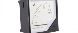
Variant of the appearance of an ammeter on LEDs in a column
The number of LEDs used will determine the threshold current value at which one of the LEDs will turn on. You can use LM3915 or a microcontroller with suitable parameters as an operational amplifier. The input will be supplied with voltage through any low-resistance resistor.
It is convenient to display the measurement results in the form of a bar chart, where the entire practically used current range will be divided into several segments of 5...10 mA. The advantage of LED is that the circuit can use elements of different colors - red, green, blue, etc.
To operate a digital ammeter you will need the following components:
- Microcontroller type PIC16F686 with 16-bit ADC.
- Configurable jumpers for final signal output. Alternatively, DIP switches can be used as electronic shunts or signal shorts in conventional electronic circuits.
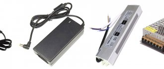
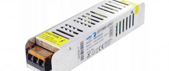
- A DC power source, which is designed for an operating voltage of 5 to 15 V (if there is a stable voltage, which is monitored by a voltmeter, 6 V is also suitable).
- Contact board where you can place up to 20 SMD LEDs.
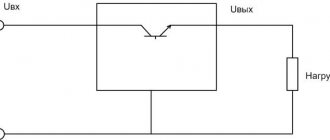
Electrical circuit of an ammeter on LED sources
DIY model
Assembling a digital ammeter with your own hands is quite difficult. First of all, this will require a high-quality comparator. The sensitivity parameter must be at least 2.2 microns. It must maintain a minimum resolution of 1 mA. The microcontroller in the device is installed with reference diodes. The display system is connected to it through a filter. Next, to assemble a digital ammeter with your own hands, you need to install resistors.
Most often they are selected as a switched type. The shunt in this case should be located behind the comparator. The division factor of the device depends on the transceiver. If we talk about a simple model, then it is used of the dynamic type. Modern devices are equipped with ultra-precise analogues. A regular lithium-ion battery can serve as a source of stable current.
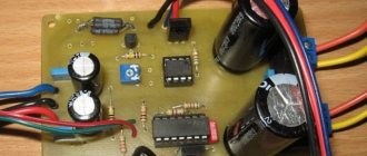
Sequence of placement and installation of the ammeter
The input current signal (no more than 1 A) is supplied from a stabilized power supply through a shunt resistor, the permissible voltage across which should not exceed 40...50 V. Then, passing through an operational amplifier, the signal is sent to the LEDs. Since the value of the current changes during the passage of the signal, the height of the column will change accordingly. By controlling the load current, you can adjust the height of the diagram, obtaining results with varying degrees of accuracy .
Mounting the board with SMD components, at the user’s request, can be placed either horizontally or vertically. Before starting calibration, the viewing window must be covered with dark glass (a filter with a magnification of 6...10x of a regular welding helmet is suitable).
Calibration of a digital ammeter consists of selecting the minimum current load value at which the LED will light. The setting is varied experimentally, for which a resistor with a small (up to 100 mOhm) resistance is provided in the circuit. The error in readings of such an ammeter usually does not exceed several percent.
Did you know that you can convert an old voltmeter into an ammeter? How to do this - watch the video:
How to convert a DC voltmeter into AC voltage
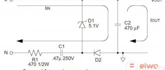
The circuit shown in Figure 1 is a DC voltmeter. To make it variable or, as experts say, pulsating, it is necessary to install a rectifier in the design, with the help of which the direct voltage is converted into alternating voltage. In Figure 2, an AC voltmeter is shown schematically.
This scheme works like this:
- when there is a positive half-wave at the left terminal, diode D1 opens, D2 in this case is closed;
- voltage passes through the ammeter to the right terminal;
- when the positive half-wave is at the right end, then D1 closes and no voltage passes through the ammeter.
A resistor Rd must be added to the circuit, the resistance of which is calculated in exactly the same way as the other elements. True, its calculated value is divided by a coefficient equal to 2.5-3. This is the case if a half-wave rectifier is installed in the voltmeter. If a full-wave rectifier is used, then the resistance value is divided by a coefficient: 1.25-1.5. By the way, the diagram of the latter is shown in Figure 3.
How to set the adjustment resistor
To do this, the current strength that passes through a specific LED is sequentially set. A regular tester can be used as a control device. A voltmeter is included in the circuit before the microcontroller, and an ammeter after it. To eliminate the influence of random ripples, a smoothing capacitor is also connected.
A practical advantage of making the device yourself (there should be no less than four LEDs) is the stability of the circuit with significant changes in the initially specified current range. Unlike conventional diodes, which will fail if short-circuited, LEDs simply do not light up.
LED diodes, like current meters in a car battery, not only save charge and preserve batteries, but also allow you to read the readings in a more convenient way.
A digital voltmeter can be built in a similar way. 12 V elements are suitable as light sources for this application, and the presence of an additional shunt in the voltmeter circuit will allow more efficient use of the entire height of the bar graph.
Please rate the article. We tried our best:)
Did you like the article? Tell us about her! You will help us a lot :)
How to properly connect a voltmeter
Anyone who does not know, but wants to check the voltage on some part of the electrical network, must ask the question - how to connect a voltmeter? This is actually a serious question, the answer to which lies in a simple requirement - the voltmeter must be connected only in parallel with the load. If a serial connection is made, the device itself will simply fail and you may receive an electric shock.
The thing is that with such a connection the current strength acting on the measuring device itself decreases. At this resistance, it does not change, that is, it remains large. By the way, never confuse a voltmeter with an ammeter. The latter is connected to the circuit in series to reduce the resistance to a minimum.
Built-in modifications
The digital built-in ammeter is produced on the basis of reference comparators. The throughput of the models is quite high, and the permissible error is about 0.2%. The minimum resolution of the devices does not exceed 2 mA. Stabilizers are used of both expansion and pulse types. Resistors are set to high sensitivity. Microcontrollers are often used without rectifiers. On average, the current conversion process does not exceed 140 ms.
Universal measuring instruments
Universal measuring instruments are more suitable for household use. Comparators in devices are often installed with low sensitivity. Thus, the permissible error is around 0.5%. The counters are of three-digit type. Resistors are used on the basis of capacitors. Triodes are found in both phase and pulse types.
The maximum resolution of the devices does not exceed 12 mA. The shunt resistance, as a rule, lies in the region of 3 ohms. The permissible humidity for devices is 7%. The maximum pressure in this case depends on the installed protection system.
Lovat device
The specified ammeter (digital) is made on the basis of a two-digit counter. The current conductivity of the model is only 2.2 microns. However, it is important to note the high sensitivity of the comparator. The display system is simple and the device is very comfortable to use. The resistors in this ammeter (digital) are of the switched type.
It is also important to note that they can withstand heavy loads. The shunt resistance in this case does not exceed 3 ohms. The current conversion process occurs quite quickly. A sharp drop in voltage can only be associated with a violation of the temperature regime of the device. The permissible humidity of the specified ammeter is as much as 70%. In turn, the maximum resolution is 10 mA.
Phase-sensitive modification device
Phase-sensitive models are sold at 10 and 12 V. The permissible error parameter for the models fluctuates around 0.2%. Counters in devices are used only of the two-digit type. Microcontrollers are used with rectifiers. Ammeters of this type are not afraid of high humidity. Some modifications have amplifiers. If you are assembling a device, you will need switched resistors. A regular lithium-ion battery can be a source of stable current. A diode is not needed in this case.
Before installing the microcontroller, it is important to solder the filter. A converter for lithium-ion will need a variable type. Its sensitivity indicator is at the level of 4.5 microns. If there is a sudden drop in voltage in the circuit, it is necessary to check the resistors. The division coefficient in this case depends on the throughput of the comparator. The minimum pressure of devices of this type does not exceed 45 kPa. The current conversion process itself takes about 230 ms. The speed of the clock signal depends on the quality of the counter.
Pulse measuring instruments
Pulse modifications are distinguished by the presence of counters. Modern models are produced on the basis of three-digit devices. Resistors are used only of the orthogonal type. As a rule, their division coefficient is 0.8. The permissible error, in turn, is 0.2%. The disadvantages of the devices include sensitivity to environmental humidity. They should also not be used at sub-zero temperatures. Assembling the modification yourself is problematic. Transceivers in the models are used only of the dynamic type.
Torekh device
The specified ammeter (digital) is manufactured with increased current conductivity. The device can withstand a maximum pressure of 80 kPa. The minimum permissible temperature of the ammeter is -10 degrees. This measuring device is not afraid of high humidity. It is recommended to install it near a power source. The division factor is only 0.8. The maximum pressure the ammeter (digital) can withstand is 12 kPa. The current consumption of the device is about 0.6 A. The triode is of the phase type. This modification is suitable for household use.