Often, when upgrading a computer, a completely serviceable power supply is left out of use. Its power is not enough to power new components. Those who upgrade hardware may accumulate a lot of such devices. A dilemma arises: to recycle power supplies or find practical use for them. One way to give your computer power supply a second life is to turn it into a lab power supply with adjustable output voltage and adjustable current limiting. You can do this modification yourself.
Marking of computer power supply wires
The power supply unit is connected to consumers inside the computer case using harnesses with connectors. A standard has been adopted according to which each supply voltage is marked with a conductor with the appropriate insulation color.
| Wire color | Voltage, V |
| Black | 0 V (ground, common) |
| Red | +5 |
| Orange | +3,3 |
| Yellow | +12 |
| White | -5 |
| Blue | -12 |
In addition to power circuits, the harnesses contain conductors with control signals (they can be found on the connector going to the motherboard).
| Wire color | Name | Function | Voltage level |
| Green | Power_ON | Signal from the motherboard - permission to turn on | +5 volts in the absence of permission, 0 volts when receiving a signal to supply voltage |
| Grey | Power_good, Power_OK | Signal to motherboard - all voltages are normal | +5 volts |
| Violet | Stand by | Standby voltage is always present if 220 volts are supplied to the power supply | +5 volts, serves to power the PC switching circuits and power the PWM circuit inside the power supply |
| Brown | Sense | Voltage regulation 3.3 volts | 3.3 volts |
Most chains will not be needed for conversion into LBP; they will need to be cut during operation.
Feasibility
Of course, working with a tool with a short cord is not nearly as convenient as using a battery-powered one. But the alteration will not take much time from a person with electrical installation skills. But it will allow you to finish urgent work. And then slowly decide what to do with the screwdriver - repair it or throw it away and buy a new one. You probably won’t want to constantly work with such a tool; a cheap Chinese electric drill with a power extension cord will be much more convenient. In addition, during prolonged operation the power supply becomes noticeably hot. In order for it to cool down, you need to periodically take breaks from work, which affects the result.
What is needed for making
More than 90% of the components for a laboratory worker are already in the computer power supply. The rest will have to be selected for a specific scheme (the elements are inexpensive and there will be few of them), but you will definitely need:
- two potentiometers for adjusting voltage and current;
- several oxide capacitors for a voltage of at least 35 volts (preferably 50+) with a capacity corresponding to the standard capacity of the +12 volt channel elements (or more if they fit in dimensions);
- terminals for connecting the load (it is convenient to use red for the positive terminal and black for the negative);
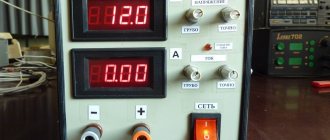
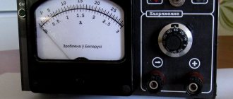
- voltmeter and ammeter for measuring output parameters (you can use analog instruments, you can use digital ones, but it is more convenient to use a double voltmeter-ammeter unit).
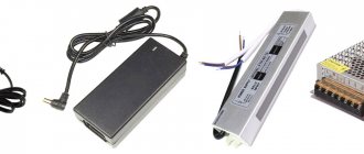
Digital current and voltage indicator.
The equipment you will definitely need is a multimeter . It wouldn’t be superfluous to use an oscilloscope to check the presence of output pulses on the PWM chip and its response to the control action if something goes wrong. You will also need a soldering iron with a set of consumables and small plumbing tools (a set of screwdrivers, wire cutters, etc.).
Recommended operating parameters.
| Options | Min. | Max. | Unit Change |
| VCC Supply Voltage | 7 | 40 | IN |
| VI Amplifier input voltage | -0,3 | VCC – 2 | IN |
| VO Collector voltage | 40 | IN | |
| Collector current (each transistor) | 200 | mA | |
| Feedback current | 0,3 | mA | |
| fOSC Oscillator frequency | 1 | 300 | kHz |
| CT Generator Capacitance | 0,47 | 10000 | nF |
| RT Generator resistor resistance | 1,8 | 500 | kOhm |
| TA Operating temperature TL494C TL494I | 0 | 70 | °C |
| -40 | 85 | °C |
Its limiting characteristics are as follows;
Supply voltage………………………………………………………..41V
Amplifier input voltage……………………………(Vcc+0.3)V
Collector output voltage…………………………..41V
Collector output current………………………………………250mA
Total power dissipation in continuous mode….1W
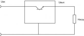
Scheme for laboratory power supply
To convert an unnecessary computer power supply into a laboratory source with an adjustable output voltage, ATX standard power supplies (but AT is also possible), made according to a PWM circuit on a TL494 chip or its analogues, are well suited.
Block diagram of an ATX standard power supply.
Although they are all built according to the same structural diagram and operate on a similar principle, the power supplies can be physically implemented differently. Therefore, the first thing to start with is to try to find a circuit diagram from an actual block.
The conversion procedure can be considered using the example of the LC-250ATX model. Having understood the principle, it will be possible to work with other similar blocks.
Initial diagram of the LC-250ATX unit.
The LC-250ATX is based on the PWM principle, implemented on the TL494 chip, standard for such circuits. It generates pulses that are amplified by switches on transistors Q6, Q7, then through transformer T2, switches on transistors Q1, Q2 create pulses on the primary winding of transformer T1. These pulses are transformed through the secondary windings and supplied to rectifiers of various voltages, of which only the +12 volt channel is of interest for conversion.
The standby voltage circuit is assembled on transistor Q3, transformer T3 and integrated stabilizer 7805. This section will also be needed for a future design. The operational amplifier LM339 is used to assemble a circuit for generating the PWR_OK signal and triggering the power supply with a signal from the motherboard.
Compound.
It contains:
— sawtooth voltage generator (SPG); — dead time adjustment comparator (DA1); — PWM adjustment comparator (DA2); — error amplifier 1 (DA3), used mainly for voltage; — error amplifier 2 (DA4), used mainly for the current limit signal; — a stable reference voltage source (VRS) of 5V with external pin 14; — control circuit for the operation of the output stage.
Then, of course, we will look at all its components and try to figure out why all this is needed and how it all works, but first we will need to give its operating parameters (characteristics).
Connection
You should not install a capacitor with a capacity of several tens of thousands of microfarads in parallel with the motor, as some experts advise. Firstly, with a starting current of about 20 A, it will be of little use. Secondly, it will make it difficult to start the power supply. If, when you gradually press the start button, the chuck accelerates and rotates normally, and after a sharp start of the screwdriver the engine stops, it means that the current protection of the power supply unit is triggered. It should not be removed from the device; you just need to increase the shutdown threshold. How to do this in practice depends on the design of your power supply. Theoretically, it is necessary to attenuate a signal at its input that is proportional to the output current.
In order not to disassemble the screwdriver and solder wires to the motor terminals, you can use an unusable battery to connect the power supply.
- Disassemble the housing of the faulty battery. To do this, use a Phillips screwdriver or an asterisk to unscrew the screws from the bottom and remove it;
- Remove the batteries from the case;
- Make a hole in the bottom for the wires;
- Insert the wires into it;
- Strip their ends, tin them and, observing polarity, solder them to the contacts at the end of the case;
- Secure the wires in the hole with a glue gun. And if you don’t have it, then wrap several turns of electrical tape around them from the side of the body and pull the wires out so that the bottom divides the winding in half;
- Assemble the body, putting the bottom in place, and screw the screws into place;
- Installation of the modified housing into the screwdriver handle is complete. Now plug the power cord into a 220V socket. Turn on the power supply switch and, by pressing the Shurik start button, check whether you did everything correctly.
Sequence of actions for converting an ATX power supply into a regulated laboratory one.
1. Remove jumper J13 (you can use wire cutters)
2. Remove diode D29 (you can just lift one leg)
3. The PS-ON jumper to ground is already installed.
4. Turn on the PB only for a short time, since the input voltage will be maximum (approximately 20-24V). This is actually what we want to see. Don't forget about the output electrolytes, designed for 16V. They might get a little warm. Considering your “bloatiness”, they will still have to be sent to the swamp, no shame. I repeat: remove all the wires, they are in the way, and only ground wires will be used and +12V will then be soldered back.
5. Remove the 3.3-volt part: R32, Q5, R35, R34, IC2, C22, C21.
6. Removing 5V: Schottky assembly HS2, C17, C18, R28, or “choke type” L5.
7. Remove -12V -5V: D13-D16, D17, C20, R30, C19, R29.
8. Changing the bad ones: replace C11, C12 (preferably with a larger capacity C11 - 1000uF, C12 - 470uF).
9. We change the inappropriate components: C16 (preferably 3300uF x 35V like mine, well, at least 2200uF x 35V is a must!) and resistor R27 - you no longer have it, and that’s great. I advise you to replace it with a more powerful one, for example 2W and take the resistance to 360-560 Ohms. We look at my board and repeat:
10. We remove everything from the legs TL494 1,2,3 for this we remove the resistors: R49-51 (free the 1st leg), R52-54 (2nd leg), C26, J11 (3rd leg)
11. I don’t know why, but my R38 was cut by someone, I recommend that you cut it too. It participates in voltage feedback and is parallel to R37.
12. We separate the 15th and 16th legs of the microcircuit from “all the rest”, to do this we make 3 cuts in the existing tracks and restore the connection to the 14th leg with a jumper, as shown in the photo.
13. Now we solder the cable from the regulator board to the points according to the diagram, I used the holes from the soldered resistors, but by the 14th and 15th I had to peel off the varnish and drill holes, in the photo.
14. The core of cable No. 7 (the regulator’s power supply) can be taken from the +17V power supply of the TL, in the area of the jumper, more precisely from it J10/ Drill a hole into the track, clear the varnish and there. It is better to drill from the print side.
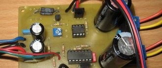
I would also advise changing the high-voltage capacitors at the input (C1, C2). You have them in a very small container and are probably already pretty dry. There it will be normal to be 680uF x 200V. Now, let's assemble a small scarf on which there will be adjustment elements. See supporting files here.
voice
Article rating
↑ Idea
The idea of creating a pulse load appeared quite a long time ago and was first implemented in 2002, but not in its current form and on a different element base and for slightly different purposes, and at that time there were not sufficient incentives and other grounds for me personally to develop this idea.
Now the stars are aligned differently and something has come together for the next incarnation of this device. On the other hand, the device initially had a slightly different purpose - checking the parameters of pulse transformers and chokes. But one does not interfere with the other. By the way, if anyone wants to research inductive components using this or a similar device, please: below are archives of articles by venerable (in the field of power electronics) engineers devoted to this topic. So, what is a “classical” (analog) EN in principle? Current stabilizer operating in short circuit mode. And nothing else. And the one who, in a fit of any passion, will be right will close the output terminals of the charger or welding machine and say: this is an electronic load! It is not a fact, of course, that such a short circuit will not have detrimental consequences, both for the devices and for the operator himself, but both devices are indeed sources of current and could, after some fine-tuning, claim to be an electronic load, like any another arbitrarily primitive current source. The current in the analog EN will depend on the voltage at the output of the power supply being tested, the ohmic resistance of the field-effect transistor channel, set by the voltage value at its gate.
The current in a pulsed electric power supply will depend on the sum of parameters, which will include the pulse width, the minimum resistance of the open channel of the output switch and the properties of the power supply being tested (capacitance of capacitors, inductance of power supply chokes, output voltage). When the switch is open, the EN forms a short-term short circuit, in which the capacitors of the power supply under test are discharged, and the chokes (if they are contained in the power supply design) tend to saturate. A classic short circuit, however, does not occur, because The pulse width is limited in time by microsecond values that determine the magnitude of the discharge current of the power supply capacitors. At the same time, testing a pulsed power supply is more extreme for the power supply being tested. But such a check reveals more “pitfalls”, including the quality of the supply conductors supplied to the power supply device. Thus, when connecting a pulsed electric power supply to a 12-volt power supply with connecting copper wires with a core diameter of 0.8 mm and a load current of 5A, the oscillogram on the electric power supply revealed ripples, which were a sequence of rectangular pulses with a swing of up to 2V and sharp spikes with an amplitude equal to the supply voltage. At the terminals of the power supply itself there was practically no pulsation from the electric power supply. On the EN itself, ripples were reduced to a minimum (less than 50 mV) by increasing the number of cores of each conductor supplying the EN - up to 6. In the “two-core” version, a minimum ripple comparable to the “six-core” version was achieved by installing an additional electrolytic capacitor with a capacity of 4700 mF at the connection points supply wires with load. So, when building a power supply, pulsed power supply can be very useful.
Design
The power of the power supply that I pulled out from under the bed is 250W. If I make a 5V/10A power supply, then precious power is lost! No matter! Let's raise the voltage to 25V, it might be suitable, for example, for charging batteries - there you need a voltage of about 15V.
To proceed further, you must first find the circuit for the source block. In principle, all power supply circuits are known and can be Googled. What exactly you need to Google is written on the board.
A friend gave me my diagram. Here she is. (Opens in a new window)
Yes, yes, we will have to crawl through all these guts. The datasheet on the TL494 will help us with this.
So, the first thing we need to do is check what maximum voltage the power supply can produce on the +12 and +5 volt buses. To do this, remove the feedback jumper thoughtfully placed by the manufacturer.
Resistors R49-R51 will pull the positive input of the comparator to ground. And, voila, we have the maximum voltage at the output.
We are trying to start the power supply. Yeah, it won't start without a computer. The fact is that it needs to be turned on by connecting the PS_ON pin to ground. PS_ON is usually labeled on the board, and we will need it later, so we won’t cut it out. But let’s turn off the incomprehensible circuit on Q10, Q9 and Q8 - it uses the output voltage and, after cutting it out, will not allow our power supply to start. Our soft start will work on resistors R59, R60 and capacitor C28.
So, the power supply started up. Maximum output voltages appeared.
Attention! The output voltages are greater than those for which the output capacitors are designed, and therefore the capacitors may explode. I wanted to change the capacitors, so I didn’t mind them, but you can’t change your eyes
Carefully!
So, we learned from +12V – 24V, and from +5V – 9.6V. It looks like the voltage reserve is exactly 2 times. Very well! Let's limit the output voltage of our power supply to 20V, and the output current to 10A. Thus, we get a maximum of 200W of power.
It seems like the parameters have been decided.
Now we need to make the control electronics. The tin case of the power supply unit did not satisfy me (and, as it turned out, in vain) - it tends to scratch something, and it is also connected to ground (this will interfere with measuring current with cheap op-amps).
For the body, I chose Z-2W, Maszczyk office
I measured the noise emitted by the power supply - it turned out to be quite small, so it is quite possible to use a plastic case.
After the case, I sat down with Corel Draw and figured out what the front panel should look like:
How to make a charger
Now let's convert the computer power supply into a car charger.
Constant voltage charger
This device charges the battery with a constant fixed voltage of 14 V. As the battery charges, the charging current will drop. As soon as the voltage at the battery terminals reaches 14 V, the current will become zero and charging will stop.
Thanks to this algorithm, the battery cannot be recharged, even if it is left on charge for a week. This is useful when servicing AGM and GEL car batteries that do not like to be recharged.
And now let’s get down to business, especially since the modification scheme is simple. We will modify the ATX power supply on the TL494 controller or its analogues (see the section above). Our task is to increase the output voltage on the +12 V bus to 14 volts. This is not difficult to do. We open the power supply, take out the board and unsolder all the power wires, leaving only yellow, black and green.
We solder the green wire in place of any black one - we issue a command to the power supply unit to unconditionally turn on when connected to the network (see the section above). We unsolder electrolytic smoothing capacitors from all power lines. In the place where the capacitor stood on the +12 V bus, we install a capacitor of the same capacity, but with an operating voltage of 35 V. We proceed to finalizing the controller. We find a resistor that connects the first pin of the microcircuit to the +12 V bus. In the diagram below it is indicated by an arrow.
We need to change its denomination. But which one? We solder it and measure its resistance. In our case, its nominal value is 27 kOhm, but depending on the power supply model, the value may vary. In place of the soldered one, install a variable resistor with a nominal value approximately twice as large. We set the resistor slider to the middle position.
We turn on the power supply and, measuring the voltage on the +12 V bus (yellow wire relative to black), rotate the slider. The voltage is easily reduced, but it cannot be increased - the overvoltage protection interferes. In order to raise the voltage to the 14 V we need, it needs to be turned off. We find a resistor and a diode in the diagram, indicated by arrows in the figure below, and unsolder them.
We turn on the power supply again, set the voltage between the black and yellow wires to 14 V. Turn it off, unsolder the resistor without touching its slider, and measure the resistance. In place of the variable we install a constant of the same denomination. We install two terminals on the case, solder the black and yellow wires to them, mark where the plus and minus are (yellow is plus, black is minus).
We turn on the power supply again, now a device converted into a battery charger. We connect the load to the terminals - the high beam lamp of the car. We measure the voltage at the terminals: if it has not decreased by more than 0.2 V, then the modification is complete. We assemble the device and use it.
Important! The final charging voltage for AGM and GEL batteries is 13.8 V, so it makes sense to reduce the output voltage from 14 V to 13.8 V.
Perhaps the only drawback of this homemade design is that it does not have protection against short circuits and reverse polarity (we turned it off). Therefore, you need to use the device carefully.