Semi-indirect counters
This connection occurs through current transformers. There are a large number of schemes for this inclusion, but the most common among them are:
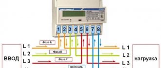
- The ten-wire connection diagram is the simplest, and therefore the most popular. To connect, you must follow the order of 11 wires from right to left: the first three are phase A, the second three are phase B, 7-9 for phase C, 10 are neutral.
- Connection via terminal box - it is more complicated than the first one. The connection is made using test blocks;
- A star connection, like the previous one, is quite complex, but requires fewer wires. First, the first unipolar outputs of the secondary winding are collected at a common point, and the next three from the other outputs are directed to the meter, and the current windings are also connected.
How to connect single-phase
A single-phase electric meter can only be connected to a corresponding single-phase network.
For installation you will need:
- screwdriver - for manipulating the terminal screw;
- knife - for stripping wire insulation;
- multimeter - to determine the phase.
In a single-phase electrical network, there are two wires at the input from the electricity supplier or transformer. They are also present if current transformers are operating in the network. It should be noted that the input wiring has already been stripped of insulation to the required level to completely fit under the terminal.
Specialist's note: do not remove insulation from the input wires to avoid problems with Energonadzor. After all, it is the excessive removal of insulation that allows you to connect devices in front of the meter, and thereby steal electricity.
There are four terminals on a single-phase electric meter. They are usually numbered from left to right:
- terminal 1 – for phase input;
- terminal 2 – for phase output;
- terminal 3 – for zero input;
- terminal 4 – for zero output.
The input wires of a single-phase network are rarely made of different colors. Therefore, you need to use a multimeter to determine where the phase is and where the zero is.
The wires are connected in series:
- First, the input phase is connected to terminal 1.
- Then, the input zero is connected to terminal 3.
- Then you need to strip the insulation on the output wires, connect it to the machine, and connect it to terminal 2 of the output phase wires, and to terminal 3 of the output zero wires.
On old induction meters, the terminal is tightened with one screw, on modern ones - with two. In any case, you should not tighten them too much. Since their strength will still be checked by the Energosbyt controller.
How to find out your network type - single-phase or three-phase
A three-phase network differs from a single-phase network in power. At home, you can determine it by several signs:
- the number of wires that come to the switchboard. For a single-phase network - 2 (less often 3, if there is grounding), three-phase - 4, 5. Three of them are phases distributed throughout the house, one is the neutral conductor, one is grounding.
- Power. For a conventional single-phase network, the figure is 220 Volts. In three-phase, the value between zero and phase is 220 Volts, and between two phases is 380. This voltage value is suitable for homes where the use of powerful appliances is likely: DKU, electric stoves, saws, machine tools.
- By the number of circuit breakers. For one phase there is one, for three - three, or one with contacts for three conductors (special device).
You can find out the type of electrical network from the documents that are provided after the installation of electricity in the house by the authorized bodies. Based on this information, it is determined which meter is needed: single-phase or three-phase.
Connecting a three-phase semi-indirect meter
These devices are connected to the network through current transformers, making it possible to use them in networks with fairly high powers (up to 60 kW). Using this accounting method, to determine the flow rate, you need to multiply the difference in readings by the set transformation ratio.
There are several types of connection for semi-indirect connection meters.
1 Star connection of current transformers
The process of connecting wires looks like this:
- contacts 3, 6, 9, 10 – are closed and connected to the neutral wire;
- contacts I2 - closed, connected to terminal 11;
- 1 – to I1 phase A;
- 4 – to I1 phase B;
- 7 – to I1 phase C;
- 2 – to L1 phase A;
- 5 – to L1 phase B;
- 8 – to L1 phase C.
Figure - Star connection diagram
Connecting a three-phase indirect meter
These devices are designed to perform electricity metering at high-voltage connections (6-10 kV and more), the connection is realized using voltage and current transformers.
Below are the main diagrams for connecting three-phase meters via current and voltage transformers:
1) Scheme for connecting a three-element meter to a four-wire network with a grounded neutral: (figure below)
2) Scheme for connecting a three-element meter to a four-wire network. Three current transformers, direct connection to voltage:(picture below)
3) Scheme for connecting a three-element meter to a three-wire line - two current transformers, three voltage transformers: (figure below)
When connecting a three-element meter according to scheme No. 3:
- phase B current is calculated with the subtraction of the zero-sequence current;
- direct, negative and zero sequence currents of the fundamental frequency are not used (symmetrical components);
- active and reactive power in phase B are calculated by subtracting the zero-sequence current from the phase current;
- Electrical energy accounting is carried out taking into account the above comments.
4) Scheme for connecting a two-element meter to a three-wire line - two current transformers, two voltage transformers (figure below)
When connecting the meter according to schemes No. 4 and No. 5:
- The zero sequence voltage of the fundamental frequency is not measured (symmetrical components);
- direct, negative and zero sequence currents of the fundamental frequency (symmetrical components) are not measured;
- connection capacities are calculated using formulas;
- Electrical energy accounting is carried out taking into account the above comments.
5) Connection diagram of a two-element meter to a three-wire line - two current transformers, direct voltage connection (figure below)
Attention!: The possibility of connecting according to a specific scheme must be indicated in the passport or manual for a specific type of meter. {SOURCE}
{SOURCE}
What is the difference between single-phase and three-phase meters?
Deciding on the choice of electricity meter for installation in an apartment is sometimes not as easy as it seems at first.
Therefore, even if you need to replace the meter and contact the seller, it is advisable to know in advance what suits you best and what characteristics the product should have.
- Counters are classified:
- by the current passing in the network;
- by the presence of phases feeding it;
- by operating voltage;
- by accuracy indicator class;
- according to the applicable tariffs.
The first step is to find out what kind of wiring is in the house. With one phase and zero or with three phases and zero, and based on this, purchase a meter.
The accuracy class of a product is not an unimportant indicator for its installation. For apartments and houses, the permissible error is 2% and not higher. Meters with lower errors are installed in industrial enterprises.
Choosing a multi-tariff device will allow you to pay for electricity consumed separately at night and during the day, at two tariffs, which helps save the family budget.
Single-phase and three-phase meters, what is the difference, this question is asked by many who are faced with the choice of a metering device.
A single-phase meter is powered by a cable consisting of two wires, a phase and a zero. The maximum voltage for such a meter is 220 V, as written on its panel.
The three-phase meter is powered by a cable consisting of four cores, three phases and zero. The voltage it operates on is 380 V.
The scope of their use also has a certain difference. Single-phase meters are mainly installed in country houses and residential buildings. Most small offices and retail establishments also install them. They are distinguished by their simple structure. They are easy to use. Taking readings from them will not be difficult.
Meters with three phases have a more complex design, and the quality of their measurements is much higher. They are installed at industrial facilities with high electricity consumption. It is allowed to install such a meter with three phases in a network with a voltage of 220 V, but installing a single-phase one in a network of three phases is not allowed.
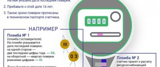
All devices undergo state verification with mandatory sealing of their housing. On new three-phase meters, when installed, the state verifier's seals must have a date that does not exceed 12 months from the time of their sealing, and for single-phase meters, not exceed 24 months.
Connections
- three-wire – for a network without a neutral wire;
- four-wire - with a neutral wire.
The connection of a three-phase meter should be carried out taking into account the following feature: devices can be connected either directly to the network or through current transformers. This depends on the current strength in the network: up to 100A - direct connection is allowed, above - through a transformer.
Three-phase meters also differ in how they are connected to the network:
- direct (direct) inclusion;
- semi-indirect installation (via a current transformer);
- indirect (using current and voltage transformers) connection.
Economic side
The multi-tariff nature of the electric meter makes it possible to configure it in such a way that the consumer can choose the tariff that would correspond to the optimal mode of electricity consumption by periods of the day or week. If a direct-connection three-phase “Matrix” meter is installed in one apartment building, then it cuts off the ability of some consumers to steal electricity. In fact, general house expenses come down to current consumption in terms of technical needs (entrances, basements, staircases).
The built-in relay makes it possible to immediately cut off the consumer in whose electrical network there is a short circuit, a current leak occurs, or the voltage has exceeded the maximum value. It should be noted that the protective shutdown function can be configured, the main thing is to configure it correctly.
Three-phase meters with semi-indirect connection
Electric meters "Mercury" with a semi-indirect connection principle are connected to the 380V alternating current network through a transformer. Thanks to this, it becomes possible to meter electricity with high network power. At the same time, in the process of calculating the resources used, the transformation coefficient must be taken into account. Today, there are quite a lot of semi-indirect circuits, the most popular of which are the following options:
- transformer connection circuit according to the “star” principle;
- ten-wire connection;
- connection diagram using test terminal boxes;
- by combining current and voltage circuits.
Considering the disadvantages of a semi-indirect connection scheme, I would like to note the difficulty of carrying out scheduled inspections by energy sales regulatory authorities.
Types of three-phase meters
There are only three types of three-phase meters
- Direct connection meters , which, like single-phase ones, are connected directly to a 220 or 380 V network. They have a throughput power of up to 60 kW, a maximum current level of no more than 100 A and also provide for the connection of small-section wires of about 15 mm2 (up to 25 mm2)
- Semi-indirect meters require connection via transformers, therefore suitable for networks of higher power. Before paying for consumed energy, you simply need to multiply the difference between the meter readings (current and previous) by the transformation ratio.
- Indirect switching meters. Their connection occurs exclusively through voltage and current transformers. They are usually installed at large enterprises, as they are designed for energy metering through high-voltage connections.
When it comes to installing any of these meters, there may be a number of difficulties associated with their connection. After all, if for single-phase meters there is a universal circuit, then for three-phase meters there are several connection diagrams for each type. Now let's look at this clearly.
Transformer connection diagrams
The reliability of the entire measuring system as a whole depends on which connection diagram for a three-phase meter via current transformers is used in this case. When choosing one or another of them, the following requirements must be taken into account:
- It is prohibited to turn on the meter through current transformers if it is intended for direct connection to the measuring network;
- When indirectly connected, it is necessary to examine the electrical circuit and determine the transformer model suitable for it (in terms of power and current);
Important! Before choosing a transformer for each specific situation, first of all, you should pay attention to its conversion coefficient, which has different values for different models. Before choosing a current transformer for a specific measuring circuit, you need to carefully study the order of the contacts to which the three-phase meter is connected
Before choosing a current transformer for a specific measuring circuit, you need to carefully study the order of the contacts to which the three-phase meter is connected.
Next, we will consider a specific diagram for connecting the meter to a three-phase circuit (see the figure below).
Schematic diagram of connection
Since the general principle of operation of all electric meters is the same, the purpose of the terminals on them is also similar. For phase “A” it looks like this:
- Contact K1 is needed to connect the current wire and one end of the transformer voltage coil to the meter;
- Terminal K2 is designed to connect the load to this phase line;
- Contact K3 is used to connect the second end of the CT voltage winding.
In the same way, the second phase “B” is connected to the meter (via terminals K4, K5 and K6), as well as the third phase “C” with contacts K7, K8, K9.
Note! Terminal K10 is the common zero, relative to it, phase voltages with the following three designations are supplied to K1, K4 and K7 of the meter: “A”, “B” and “C”. The disadvantages of the combined circuit include a large error in measuring power consumption, as well as the inability to detect a breakdown in the transformer windings
The disadvantages of the combined circuit include a large error in measuring power consumption, as well as the inability to detect a breakdown in the transformer windings.
In practice, a simpler scheme for connecting an electric meter is most often used, according to which a combined connection of secondary current circuits is carried out. It functions as follows:
- Phase wires are connected to the current contact of the meter from the circuit breaker. To simplify the circuit, the second phase voltage terminal is connected to it;
- We select the phase input of the coil so that it is also the output of the primary winding of the CT. It is subsequently connected to the load through distribution circuits;
- The beginning of the secondary transformer winding is connected to the first contact of the meter's current coil (according to one of the phases);
- The end of the secondary transformer coil is connected to the end of the current winding of the connected counter mechanism.
All remaining phases are connected in the same way.
The connection and grounding of the secondary windings of the meter is carried out in accordance with the requirements of the PUE (they are carried out according to the “star” circuit).
Education of a full star
Thanks to this organization of connecting contacts, a seven-wire circuit is obtained (as opposed to a 10-pin circuit). In conclusion, it should be recalled that when connecting via a TT, a competent choice of its type is important.
Choosing the right current transformer means taking into account that the maximum permissible current value in the secondary winding cannot exceed 40% of the nominal value, and the minimum - 5%. All phase voltages connected to the meter must follow a certain order, which is controlled using a special device (phase meter).
Possible problems
There should be no technical problems with connection. In this case, the meter readings will be displayed correctly on the meter display.
Let's look at various situations and possible problems:
- Connections at home with a normal load not exceeding 10 kW. In this case, there is a problem with registering the device. The sales organization has the right not to register and seal it. Arguing that the electric meter is not used for its intended purpose. Although there are no strict rules, the inspector will formally be right. Everything will depend on the inspector;
- Technical conditions have been issued for connecting the house to a three-phase network, but there are no technical capabilities. In this case, the inspector has the right to register the device and seal it. But he will give a temporary permit that lasts for years until the power grid corrects the situation;
- Permission was issued to connect to a single-phase network with a power of 15 kW. Electrical networks rarely do this, but it happens in life. Single-phase meters are designed for currents not exceeding 60A. And a load of 15 kW consumes a current of 75 A. A three-phase direct connection meter is designed for 100 A. Therefore, as an exception, energy sales will give permission to install a three-phase meter;
- Installing a meter in a garage or gardening community. Everything is simple here. The local electrician does not care at all what kind of metering device is installed in the box or house. The main thing is that it shows the energy consumption correctly.
From the above we can conclude that three-phase electricity meters can be used in a single-phase network. Electricity consumption readings are displayed correctly. However, problems arise during registration, the solution of which depends on the inspector of the service organization.
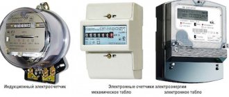
Modern electricity meters
Home / Articles / Modern electricity meters
Electricity meters are an integral part of modern electrical equipment. Meter readings are used in commercial payments for electricity, as well as in technical accounting systems organized at enterprises to solve internal problems.
The range of modern electricity meters is huge. It includes the simplest counters with a mechanical reading device, and multifunctional devices that provide display of current values, as well as recording into non-volatile memory, storage and transmission of a large number of parameters to automated systems.
Below is a conditional classification of electricity meters, which will allow you to more specifically navigate the metering devices on the market.
Induction and electronic meters. Since induction meters do not meet the requirements of regulatory documents for accuracy class, they will not be considered in this material. We will only talk about electronic meters.
Single-phase and three-phase meters. Depending on the number of connected phases, meters are single-phase and three-phase. Single-phase meters are operated at a rated network voltage of 230V. Three-phase meters are designed for a nominal voltage of 3x57.7/100V (phase voltage 57.7V, linear - 100V) and 3x230/400V (phase voltage 230V, linear - 400V). However, there are meters with an extended operating voltage range. For example, the TsE6850M-Sh31 meter (Energomera Concern) operates in the range of rated phase voltages 57.7...220V. Counters PSC-4) in the range: 3x(57.7…115)/(100…200)V or 3x(120…230)/(208…400)V.
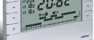
Single-tariff and multi-tariff meters. Single-tariff meters keep end-to-end electricity metering regardless of the time of day or day of the week. In a number of regions of our country, combined tariffs are used, when electricity costs more during the day than at night. Also, a reduced rate may apply on weekends and holidays. This is done in order to equalize the load during working and non-working hours. Consumers are encouraged to use energy-intensive equipment during the period when a cheaper tariff is valid. Meters that allow you to record electricity at several tariffs are called multi-tariff. Most often, manufacturers include the possibility of metering at four tariffs, but you can find meter models with three and eight tariffs. During commissioning, the meters are set to local time and programmed according to the tariff schedule adopted in a particular region. Tariff switching is carried out by an internal rater. The LCD indicator of the meters displays the amount of electricity consumed for each tariff, as well as the amount for all tariffs. Multi-tariff meters can be programmed for single-tariff metering.
Direct and transformer connection of meters to the electrical network.
Single-phase meters are connected directly to the network. Operating current ranges – 5(50)A, 5(60)A, 5(80)A, 10(80)A, 10(100)A, where the number in front of the bracket indicates the value of the rated current, the number in brackets indicates the value of the maximum current Three-phase meters used on the high-voltage side of transformer substations are connected to the network through high-voltage current and voltage transformers. In low voltage electrical networks, both direct and transformer connected meters are used. The maximum current for which direct switching meters are manufactured is 100A. If the current strength in the controlled network exceeds 100A, then transformer switching meters are used. Sometimes there are cases when transformer switching meters are used with a load current of less than 100A. There may be several reasons for such a decision. In the future, an increase in power consumption is expected. Or vice versa, consumption is reduced during repair, reconstruction or shutdown of a piece of equipment. If the power consumption during the operation of the enterprise can vary widely, then it is more economically profitable to replace the current transformers than to install a new meter. For transformer connection meters, the operating current may differ. If transformers with a secondary winding current of 5A are used, then the rated and maximum current values can take the following values: 1(7.5)A; 5(7.5)A; 5(10)A. When the current of the secondary winding of the measuring transformer is equal to 1A, the range of operating currents of the meter is within 1(2)A.
Directly connected three-phase meters are designed to operate in one of the following ranges: 5(50)A, 5(60)A, 5(80)A, 10(80)A, 5(100)A, 10(100)A.
Active, active and reactive energy meters. Existing meters are divided into active energy meters and active and reactive energy meters.
Active energy meters are usually used when the load is resistive in nature. This load includes electric stoves with burners, water heaters, irons, and incandescent lamps. In recent years, power grid subscribers, including those connected to single-phase networks, have experienced a significant increase in the reactive component of their load. Even in the household sector, hand-held power tools, small-sized machines and welding machines are often used. In lighting, incandescent lamps are being replaced by other light sources. Therefore, metering devices were required that would more fully take into account electricity consumption. Active and reactive energy meters successfully solve this problem. They have expanded functionality, control a larger number of parameters, and can be integrated into automated energy metering systems.
Accuracy classes of electricity meters. The meters are produced with accuracy classes 0.2s, 0.5s, 1.0, 2.0. Single-phase meters must have an accuracy class of at least 2.0. For three-phase ones - not lower than 1.0. The requirements for the use of meters of one or another accuracy class are set out in the Decree of the Government of the Russian Federation dated May 4, 2012 N 442 (as amended on September 27, 2018) “On the functioning of retail electricity markets, complete and (or) partial restrictions on the mode of consumption of electrical energy.”
For active and reactive energy meters, the accuracy class for active and reactive energy metering channels is indicated separately. For example, the Mercury 234 ART-03P counter has an accuracy class of A/R – 0.5s/1.0. Typically, the accuracy of reactive energy measurements is one step lower than the accuracy of active energy measurements. But sometimes there are meters, for example, those produced by Energomera Concern JSC, whose accuracy class for active and reactive energy is the same. Type of reading device. To take readings directly from metering devices, mechanical reading devices (OU) and liquid crystal indicators (LCD) are used. Mechanical op-amps are usually installed on active energy meters that do not have digital interfaces. More complex devices are equipped with LCDs, as they are more informative.
The quality of information displayed on the LCD may depend on the ambient temperature. At a temperature of -200C and below, the indicators may not go out. At the same time, the meters remain operational and continue to account for electricity. When the temperature rises, the information display is restored. A number of meters are equipped with LCD backlighting, which makes it easier to take readings in low light conditions.
Digital interfaces for transmitting information to control rooms or portable devices. For multifunctional meters, only a small part of the information is displayed on a liquid crystal display. An archive of consumed energy values, a power profile, power grid quality parameters, and an event log are stored in the non-volatile memory of the meters. You can only access the entire array of information using digital interfaces. These include RS-485, CAN, GSM/GPRS, PLC, RF, Ethernet, optical port. The most widely used serial interface is RS-485. Its advantages include the ability to connect dozens and even hundreds of devices into a network, as well as a large length of connecting lines, up to 1200 meters. In such a network, each device is assigned an individual network address. Polling is carried out only upon request from the control center. The meters themselves do not broadcast anything to the network. Some models of Mercury meters (Mercury 200.04, Mercury 230AR-01CL, -02CL, -03CL, Mercury 230ART-01CLN, -02CLN, -03CLN) use the CAN interface (Controller Area Network). However, the number of such models has been reduced in recent years. CAN was developed by Bosch for moving objects, primarily for vehicles. Subsequently, this interface was used in industry. Its peculiarity is that there can be several controllers in the network and slave devices can independently transmit information to the upper control level, for example, in the event of emergency situations or when the most important parameters exceed the permissible limits. However, such functionality is not implemented in Mercury meters. Regardless of which interface is used - RS-485 or CAN, the meters operate as slave devices and the information received from them during polling will be completely identical. That is, the difference between these interfaces lies only in the use of a different element base. RS-485 and CAN are industrial interfaces and it is not possible to connect them directly to personal computers. This problem is solved by using RS-485 – USB and CAN – USB interface converters. Both general industrial models and devices offered by meter manufacturers can be used. To build an automated electricity metering system using RS-485 or CAN interfaces, it is necessary to lay an additional information line. Such a line will not be required if electrical network wires are used to transmit information to and from meters. This technology is called PLC (Power Line Communication). In practice, this technology is implemented through the installation of a PLC interface module in the meters. However, personal computers, as is the case with RS-485, do not have ports capable of receiving information in PLC format. Therefore, additional devices are required that must convert information transmitted in one of the industrial standards into PLC format and vice versa. These devices are included in hubs, communicators, data transmission devices, etc. The specific name depends on the manufacturer. The use of meters with a PLC interface only makes sense if you plan to deploy an automated commercial electricity metering system. Otherwise, the consumer overpays for functionality that is not used. The difference in the cost of meters with the same type of functionality, without PLC and with PLC can be tens of percent.
When meters are located at remote sites, very often they are polled via GSM/GPRS modems (gateways). The GSM modem can be built-in or external. To organize communication, an external modem is connected to the output of the meter’s RS-485 interface. Manufacturers, as a rule, offer branded GSM modems (gateways, communicators). Their cost is usually higher than common industrial analogues. But branded devices are configured to work with specific types of meters, which makes pairing them easier and reduces the time of communication sessions. RF interfaces also allow you to abandon wire lines, since information is exchanged via a radio channel. A radio channel can be organized between the meter and the upper level of the system, as well as between the meter and the user terminal. The second option is used to interrogate meters installed on power transmission line supports or in cases where access to the meter is difficult. In Russia, several frequency ranges have been allocated, the use of which does not require obtaining permits. Information transmission in electricity metering systems can be carried out at the following frequencies: 433.075-434.750 MHz, 868.7-869.2 MHz and 2400-2483.5 MHz. However, these ranges are subject to restrictions on the power of transmitting devices by Decree of the Government of the Russian Federation dated October 12, 2004 N 539 (as amended on September 25, 2018) “On the procedure for registering radio electronic equipment and high-frequency devices.” For the first two ranges, the transmitter radiation power should not exceed 10 mW. The regulatory framework does not require the use of any one range in electricity meters from among those permitted. Therefore, each manufacturer chooses the frequency ranges that are preferable to them. For example, in MIRTEK 32 meters radio modules with a frequency of 433 or 2400 MHz can be used. Wireless automated systems for monitoring and accounting of housing and communal services resources based on meters with the FOBOS-1 and FOBOS-3 radio modules use a frequency of 868.8 MHz. Meters Mercury 208.LF and Mercury 238.LF also use the 868 MHz band for communication with the Mercury 258.2F display unit. MAYAK 302ARTN.132T meters exchange information with remote terminals at a frequency of 2400 MHz. Since the power of radio modems is low, the communication range will depend on the nature of the building - urban or rural, as well as on the intensity of interference in the selected range. ZigBee technology using the 2400 Hz range allows you to significantly increase the distance between the dispatch center and meters. Much work to standardize this communication protocol allows devices from different manufacturers to be included in the system. The main idea behind ZigBee technology is that such a system is self-organizing and self-healing. Thanks to this, network traffic is automatically routed, the appearance of new devices is determined, and alternative information transmission routes are selected in the event of failure of individual elements. Reliable operation of the system is achieved through redundant connections of each of its links. That is, it is not a hierarchical, but a network structure that is implemented, when each element of the system has a connection with adjacent devices. In an automated system for monitoring and accounting for electricity, built on the basis of ZigBee technology, each meter can become a repeater of information messages. Due to this, the distance from the most remote device to the control center can be several kilometers. Ryad, JSC "NZiF") have introduced the ability to use Ethernet modules in their meters, which allows you to connect these devices to local computer networks without the use of additional adapters. Optical ports are also used to configure and interrogate meters. On the front panel of most modern meters there is a special window on which is placed an optical port adapter that connects to the USB port of a computer. This method of exchanging information with the meter does not involve transmitting information over long distances, but allows you to quickly perform the necessary operations, even if the meter interface terminals are under a sealed cover. In order to program the meter before installation or take readings from it during operation, you need appropriate software installed on your computer. This can be a free configuration tool or commercial software.
All leading meter manufacturers now have devices that can be adapted to a specific consumer. There are two main approaches to this issue. The first is when the meter configuration is determined by the customer from the very beginning. This approach is practiced by Elster Metronica. In this company, any counter is manufactured on the basis of a completed questionnaire. In the second approach, the consumer selects a meter model that allows the installation of expansion cards. These meters are initially ready-made products with a certain functionality and a set of interfaces. Further, the capabilities of the device are expanded by installing additional interface boards selected from the standard set. Pulse outputs. Many modern electricity meters have pulse outputs. Their number is equal to the number of electricity metering channels. Active energy meters have one pulse output. Bidirectional meters have four: one for the forward direction of active energy, one for the reverse direction of active energy, one for the forward direction of reactive energy and one for the reverse direction of reactive energy. When the meter is switched on to the verification mode, the pulse outputs operate as verification outputs; in operating mode, as telemetry outputs. The operating principle of pulse outputs is based on the fact that the pulse repetition rate is proportional to the current flowing through the measuring circuits. Each type of counter has a parameter called “counter constant”. The meter constant is measured in pulses/(kW*hour) for active energy metering channels and in pulses/(kVAR*hour) for reactive energy metering channels. These values are indicated in passports (operation manuals) and on the front panel of the meters. Before the advent of digital interfaces, there were automatic electricity metering systems based on counting pulses transmitted by meters. This method is currently obsolete. Some meters provide the ability to programmatically change the operating mode of pulse outputs. Instead of a pulse generator, the outputs can be connected to a load control device, which changes the impedance of its output circuit depending on whether there is a load limit command or not.
Design. Meters intended for installation in transformer substations will distribute
In spruce devices and electricity metering cabinets, they are manufactured in the form of a monoblock. Such meters can have housings for mounting on a panel using three screws or on a 35 mm DIN rail. There are meters whose housings allow them to be mounted both on a panel and on a rail. For example, CE 101 in R5.1 housing. Meters for installation on power line supports consist of two parts - a meter block and an indication device. Below are several types of meters, the design of which provides for this installation method: a) single-phase - Mercury 208, RiM 129, MAYAK 103ARTN, CE208-C2, NP523, NP71E.2-1-5, AD11S; b) three-phase - Mercury 238, RiM 489.18, Mayak 132ARTN, CE308 C36 DLP, AD13S. Each manufacturer calls the display device differently. JSC RiM has a remote display, JSC NZiF has a remote terminal, LLC Incotex has a display unit. Communication between the meter and the display device is organized via RF or PLC interfaces. If communication is organized via a radio channel, then the display device can be portable. When using the PLC interface, the display device must be connected to the network. Indication devices can be interfaced with some meters in a monoblock housing. The remote display RiM 040, produced by RiM JSC, allows you to interrogate RiM 489 meters installed in transformer substations. Matrix LLC has introduced the ability to interrogate series 8 meters of type AD11A, AD13A using the custom display CIU8.B-2-1. In accordance with clause 1.5.13 of the “Rules for the Construction of Electrical Installations” (PUE), each installed meter must have seals with the state verifier’s mark on the screws securing the meter casing, and a seal from the energy supply organization on the clamping cover. Sometimes you can see additional seals, brands or holographic stickers on the meters. This sealing is made by the manufacturers to protect against unauthorized opening of the top cover.
Number of accounting directions. Currently, the industry offers unidirectional, bidirectional and combined electricity meters. Unidirectional meters can only be used on lines with power flowing in one direction. Bidirectional electricity meters record electricity in forward and reverse directions. They are used in cases where there are flows of electricity between networks or business entities. Meters are located on the border of the balance sheet of electric networks. The obtained readings are used in calculations for intersystem electricity flows. Since industrial networks are three-phase, bidirectional meters are most often three-phase. Although there are also single-phase bidirectional meters. Below are some types of bidirectional meters and their manufacturers. Mercury 234ART2 and Mercury ARTM2 (Inkotex LLC), CE301, CE303, CE304, CE308 with the symbol “Y” in the designation, TsE6850M with the symbol “2H” in the designation (Energomera Concern), MAYAK 103 ART, MAYAK 302ART , PChS-4TM.05MK isp. 00…07, 20, 21 (JSC NZiF), NP73, AD13, NP71, AD11 (LLC Matrix). Combined meters have three metering channels and are designed to account for active energy, regardless of the direction of current in each phase of the network, and reactive energy in forward and reverse directions and can only be used on lines with energy flow in one direction.
Load management. There are two ways to limit the load - directly through power relays built into the meter and through external devices. External devices can be activated by auxiliary low-current meter relays or by changing the resistance at the meter pulse outputs, switched to load control mode. In order for the meter to limit or turn off the electricity supplied to the consumer, it is necessary to programmatically set certain parameters. This operation can be performed both before putting the meter into operation and during operation. If the meter is part of an automated commercial electricity metering system, then the command to limit electricity can be given remotely by the control room operator. The load control function is implemented in direct-on counters.
Multifunctional counters. Multifunctional meters display information on current energy consumption values and network parameters on LCD indicators. The network parameters include: - instantaneous values of active, reactive and apparent power for each phase and for the sum of phases, indicating the direction of the apparent power vector; — effective values of phase currents and voltages, including those measured at one period of the network frequency, for the purpose of analyzing power quality indicators; - values of angles between phase voltages; — network frequency; — power factors for each phase and for the sum of phases. However, a huge amount of information is only available when connected to a computer with specialized software installed. In this case, the following data becomes available: - on energy consumption not only for the previous day and month, but also for a period of one to three years; — about the power profile to depth, depending on the memory size and integration period; — power quality parameters – date and time of exit and return of the lower permissible and maximum permissible voltage value of each of the phases and network frequency; — values of morning and evening power maximums; — event log: date and time of turning on/off the meter, correction of the current time, turning on and off the meter or individual phases, exceeding the energy limit according to tariffs, opening and closing the main cover of the device and other parameters depending on the type of device and manufacturer.
Analysis of this data opens up opportunities for developing measures to optimize energy consumption and prevent emergency situations.
Timing for putting electricity meters into operation. The PUE (clause 1.5.13) stipulates that newly installed three-phase meters must have state verification seals no more than 12 months old, and single-phase meters must have state verification seals no more than 2 years old. If this requirement is violated, then the meters must be subjected to regular verification.
Types of metering devices
Depending on the principle of operation, three-phase electricity meters can be:
- electromechanical (induction);
- electronic.
The first option is discussed above. Such metering devices have recently been used less frequently, as they have a low accuracy class, have a small range of operating temperatures and do not allow saving electricity if it is possible to maintain multi-tariff metering of electricity consumption.
Electronic metering devices are free from these disadvantages, since they do not contain mechanical parts. In addition, thanks to electronic filling, such devices can transmit readings remotely. They can be freely mounted even outdoors on power poles. Of course, such devices cost several times more than their induction counterparts, but this cost can easily be recouped through the use of multi-tariff metering, for example, by using powerful consumers at night.
Consequences of incorrect connection
In addition, an unprofessional approach to installing electrical equipment has a detrimental effect on it during operation.
In case of cable overload (current exceeds the nominal value), poor connection of contacts or connection of copper and aluminum wiring, they will soon manifest themselves. In this case, emergency situations are inevitable. And their first sign will be the smell of burnt wiring.
To properly connect an electric meter, you need to have knowledge of electrical engineering concepts. If you install it yourself, you can watch video tutorials on this topic. However, we should not forget that a professional approach can save not only property, but also life. Therefore, if you are not confident in your capabilities, then it is better to minimize the risks.
To control and account for consumed electrical energy, you need a special device - an electric meter. Both in large industrial enterprises and in private apartments, when concluding an agreement for the supply of electricity, this device cannot be avoided.
When installing a meter to calculate consumed electricity, you must correctly connect it to the power supply circuit.
Electricity meters can be either single-phase or three-phase, with direct or indirect connection.
In this article we will tell you in detail how to independently connect both types of electricity meters.
How does a three-phase electricity meter differ from a single-phase one?
Single-phase meters account for electricity in two-wire AC networks with a voltage of 220V. And three-phase - in three-phase alternating current networks (3 and 4-wire) with a nominal frequency of 50 Hz.
Single-phase power is most often used for electrification of the private sector, residential areas of cities, office and administrative premises, in which the power consumption is about 10 kW. Accordingly, in this case, electricity metering is carried out using single-phase meters, the great advantage of which is the simplicity of their design and installation, as well as ease of use (taking phases and readings).
But modern realities are such that over the past couple of decades the number of electrical appliances and their power has increased significantly. For this reason, not only enterprises, but also residential premises - especially in the private sector - are connected to three-phase power. But does this actually allow you to consume more power? According to the technical conditions for connection, it turns out that the power supply from a three-phase and single-phase network is almost equal - 15 kW and 10-15 kW, respectively.
The main advantage is the ability to directly connect three-phase electrical appliances, such as heaters, electric boilers, asynchronous motors, and powerful electric stoves. More precisely, there are two advantages at once. Firstly, with a three-phase power supply, these devices operate with higher quality parameters, and secondly, “phase imbalance” does not occur when several powerful electrical receivers are used simultaneously, since it is always possible to connect electrical appliances to a phase that is free from drawdown through “distortion”.
The presence or absence of a neutral wire determines which meter will need to be installed: a three-wire one if there is no “zero”, and if there is one, a four-wire one. For this purpose, there are corresponding special symbols in its marking - 3 or 4. Direct and transformer connection meters are also distinguished (for currents of 100A or more per phase).
To get a clearer idea of the advantages of single-phase and three-phase meters over each other, you should compare their pros and cons.
Let's start with where three-phase is inferior to single-phase:
- a lot of hassle in connection with the mandatory obtaining of permission to install a meter and the likelihood of a refusal
- Dimensions. If you previously used single-phase power with a meter of the same name, you should take care of the place to install the input panel, as well as the three-phase meter itself.
Protective and transition devices
Any three-phase electricity meter connected to high-voltage networks through current transformers must be protected from overvoltages that often occur in power supply lines. For this purpose, special devices are installed in series with it to limit the voltages that arise in the line in an emergency. They are found under various names, the most common of which is oin.
This device, in its functionality, resembles a circuit breaker. But it is not triggered by overcurrent, but is used as a voltage limiter on the section of the supply line into which the three-phase meter is connected.
Below is a diagram according to which this device is installed in the circuit of the equipment it protects.
Before installing a three-phase meter in the supply circuit, experts advise using another special device connected to the terminal block of the meter itself.
The indicated product, found under the designation IKK, has in its design a number of jumpers that allow you to switch the connection in a user-friendly way. The appearance of this device and the diagram for connecting it to the power circuit are shown in the photo below.
From this photo it is clear that when using IKK, the installation and dismantling of any type of metering device is significantly simplified, which is very convenient when carrying out their repair, for example.
Additional installation of the IKK is carried out by connecting it in parallel to an existing terminal block.
In the final part of the review, we note that the previously discussed meter switching schemes are selected depending on their operating conditions and the nature of the existing electrical network. To organize their correct connection, it is important to take into account all the factors that affect the performance of a particular counting device, determined not only by its class, but also by the features of the reading-taking mechanism.
Preparatory work
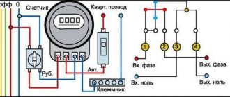
In general, connecting an electric meter, the circuit of which is known, will not be difficult.
We sorted out the contacts. Video: connecting a single-phase single-tariff electric energy meter Connecting a three-phase electric meter There are two types of connecting a three-phase meter, direct and indirect, through isolating current transformers.
The box consists of two main parts: an outer one - a protective cover with an inner door, which includes one or more DIN rails, their number depends on how many installation positions the box is designed for. The power consumed in this case is distributed between three phase conductors, as a result of which the current in each of them is reduced to approximately 2.5 Amperes. However, in real life, an input machine can be installed behind the meter along the flow of electricity.
It is necessary to observe the phasing of the winding connection, otherwise the meter readings will be incorrect. And many people think that only a professional electrician can do such work. Additional installation of the IKK is carried out by connecting it in parallel to an existing terminal block.
Installing an electricity meter for a garage is similar. Contacts of automatic switches Let's start with the input circuit breaker. All single-phase meters, both electronic and induction, have only four terminals for connection: Contact 1 - for connecting the phase supply wire; Contact 2 - for connecting the phase wire going to the electrical receivers; Contact 3 - for connecting the neutral supply wire; Contact 4 - for connecting the neutral wire going to the electrical receivers.
They can be either metal or plastic. If the induction counter is placed in a horizontal position, it stops. From these terminals, the conductors are connected to a fire protection RCD, after which the electricity is distributed among single-pole circuit breakers, and the neutral working conductor is connected to a common zero bus. As a rule, in most cases, such a device is a two-pole circuit breaker.
Installation of an electric meter and modular equipment
From the input machine, this is usually a two-pole device, one phase wire is connected to the 1st contact of the electric meter, and a jumper connects the second terminal to the distribution machine. How to connect the machine, as well as how to connect the meter, can be seen from the attached diagrams. To avoid confusion if any faults occur, be sure to mark your circuit breakers and meter with the apartment number. From the terminals of the secondary winding of the current transformer, phase A, wire with cross section 1. External conditions should also be taken into account - temperature, humidity and others. The transition to a modern and universal three-phase power supply circuit is also preferable from the point of view of maintaining the required temperature balance, ensuring safe operating conditions for the entire power supply system.
Pulling contacts Surely, if a person has installed electrical wiring in an apartment on his own, he already knows that the contacts of the connections must be tight enough to prevent heating and failure of the wires. Transformer connection meters are mainly used in metering units of industrial enterprises. Most often it is installed in the corridor or at the front door. This should be the case according to the PUE, but if the input machine cannot be sealed, the network organization will not allow such a meter connection scheme. Now, you need to distribute the phase coming from the meter among all single-pole circuit breakers outgoing in directions. Do-it-yourself installation of the SIP input panel and meter
In conclusion - briefly about the main points
- The advantage of single-phase meters is the simplicity of their design and installation, as well as ease of use (taking phases and readings)
- But three-phase ones have the highest accuracy of readings, although they are more complex in design, have large dimensions and require a three-phase input.
- Allows you to save money. Thanks to tariffs such as day and night, from 11 pm to 7 am you can use up to 50% less energy than with the same load, but during the day.
- Possibility to select accuracy class. Depending on whether the purchased model is intended for use in a residential area or in an enterprise, there are items with an error of 0.2 to 2.5%
- The event log allows you to notate changes regarding voltage dynamics, active and reactive energy and directly transmit them to a computer or the corresponding communication center
- The presence of a built-in electric power modem, with the help of which indicators are exported via the power network.
Selecting a meter
Before connecting a 3-phase meter suitable for a private home, you need to make sure that the use of this brand of device is provided for by the type of supply network. Next, you will need to find out what operating current the purchased meter should be designed for. In this case, one should proceed from the amount of power taken into account by the device and the power consumed in the load. As a rule, in this case, they are guided by the rating of the input machine, according to which the following options are possible:
- when using a switch with a setting of “40”, the operating current of the meter should be 60 Amperes;
- with a machine rating of 40-60 Amperes, you should purchase a metering device with a current limit of 100 Amperes.
A big advantage of a three-phase meter is the ability to record the load graph and keep track of power consumption for any time period
When choosing such a device, it is important to inquire about its accuracy class (from 0.2 to 2.5) and permissible temperature range. It is desirable that the last indicator be as wide as possible (from – 20º C to 50º C)
Which device should you choose?
Although most often those who want to install a meter are literally informed about which model is required for this and it is very problematic to agree on its replacement, despite its obvious non-compliance with the requirements, it is still worth learning the basics of the criteria that a three-phase meter must meet in terms of its characteristics .
The choice of a meter begins with the question of its connection - through a transformer or directly to the network, which can be determined by the maximum current. Direct connected meters have currents of the order of 5-60/10-100 amperes, and semi-indirect ones - 5-7.5/5-10 amperes. The meter is also selected strictly according to these readings - if the current is 5-7.5A, then the meter should be similar, but not 5-10A, for example.
Secondly, we pay attention to the presence of a power profile and an internal tarifficator. What does this give? The tariffifier allows the meter to regulate tariff transitions and record the load schedule for any time period. And the profile records, records and stores power values over a period of time.
For clarity, let’s consider the characteristics of a three-phase meter using the example of its multi-tariff model:
The accuracy class is determined in values from 0.2 to 2.5. The larger this value, the greater the percentage of error. For residential premises, class 2 is considered the most optimal.
- nominal frequency value: 50Hz
- rated voltage value: V, 3x220/380, 3x100 and others
If, when using an instrument transformer, the secondary voltage is 100V, a meter of the same voltage class (100V) is required, as well as a transformer with a value of total power consumed by voltage: 5 VA, and active power - 2W
- rated-maximum current value: A, 5-10, 5-50, 5-100
- maximum value of total power consumed by current: up to 0.2VA
- inclusion: transformer and direct
- registration and accounting of active energy
In addition, the temperature range is important - the wider it is, the better. Average values range from minus 20 to plus 50 degrees.
You should also pay attention to the service life (depending on the model and quality of the meter, but on average it is 20 -40 years) and the inspection interval (5-10 years).
A big plus will be the presence of a built-in electric power modem, with the help of which indicators are exported via the power network. And the event log allows you to notate changes regarding voltage dynamics, active and reactive energy and directly transmit them to a computer or the appropriate communication center.
And the most important thing. After all, when choosing a meter, we first of all think about saving. So, to really save on electricity, you should pay attention to the availability of tariffs. According to this feature, meters are available in single, double and multi-tariff types.
For example, two-tariff ones consist of a combination of “day-night” positions, continuously replacing each other according to the schedule “7 am -11 am; 11 am -7 am” respectively. The cost of electricity at night is 50% lower than during the day, so it makes sense to operate appliances that require a lot of energy (electric ovens, washing machines, dishwashers, etc.) at night.
Connecting a three-phase semi-indirect meter
These devices are connected to the network through current transformers, making it possible to use them in networks with fairly high powers (up to 60 kW). Using this accounting method, to determine the flow rate, you need to multiply the difference in readings by the set transformation ratio.
There are several types of connection for semi-indirect connection meters.
1 Star connection of current transformers
The process of connecting wires looks like this:
- contacts 3, 6, 9, 10 – are closed and connected to the neutral wire;
- contacts I2 - closed, connected to terminal 11;
- 1 – to I1 phase A;
- 4 – to I1 phase B;
- 7 – to I1 phase C;
- 2 – to L1 phase A;
- 5 – to L1 phase B;
- 8 – to L1 phase C.
Figure - Star connection diagram
Ten-wire circuit for switching on the meter
10-wire circuit
This circuit is characterized by improved electrical safety, due to the isolation of current and voltage circuits from each other.
Connecting a three-phase indirect meter
These devices are designed to perform electricity metering at high-voltage connections (6-10 kV and more), the connection is realized using voltage and current transformers.
Below are the main diagrams for connecting three-phase meters via current and voltage transformers:
1) Scheme for connecting a three-element meter to a four-wire network with a grounded neutral: (figure below) 2) Scheme for connecting a three-element meter to a four-wire network. Three current transformers, direct connection to voltage: (figure below) 3) Connection diagram of a three-element meter to a three-wire line - two current transformers, three voltage transformers: (figure below)
When connecting a three-element meter according to scheme No. 3:
- phase B current is calculated with the subtraction of the zero-sequence current;
- direct, negative and zero sequence currents of the fundamental frequency are not used (symmetrical components);
- active and reactive power in phase B are calculated by subtracting the zero-sequence current from the phase current;
- Electrical energy accounting is carried out taking into account the above comments.
4) Scheme for connecting a two-element meter to a three-wire line - two current transformers, two voltage transformers (figure below)
When connecting the meter according to schemes No. 4 and No. 5:
- The zero sequence voltage of the fundamental frequency is not measured (symmetrical components);
- direct, negative and zero sequence currents of the fundamental frequency (symmetrical components) are not measured;
- connection capacities are calculated using formulas;
- Electrical energy accounting is carried out taking into account the above comments.
5) Connection diagram of a two-element meter to a three-wire line - two current transformers, direct voltage connection (figure below)
Attention!: The possibility of connecting according to a specific scheme must be indicated in the passport or manual for a specific type of meter. Direct connection three-phase meter Energomera
Direct connection three-phase meter Energomera
Today's article is devoted to disassembling the direct connection meter Energomer TsE 6803V. Let me remind you that I already have a similar article about the design of a single-phase Energomer meter. There is also information on how the meter counts electricity.
This time – not one, but three phases!
For those who are more deeply interested in the topic, I have already written in detail in another article how the three phases differ from one.
I have another popular article on such meters - about connecting and installing three-phase meters. It contains very detailed instructions on how to secure and connect such meters.
I came across a three-phase meter that has been taken out of service. We'll take it apart down to the screw, get ready!
Disadvantages of a three-phase meter
- electronic ones take into account the converter pulses and transmit them to the controller;
- three-phase induction meters read the number of revolutions of a disk driven by an induced magnetic field.
Direct connection meters, they are connected to cable distribution with a cross-section of 15 to 25 mm². Do not connect a thick wire to the terminals of direct connection devices.
The manufacturer indicates how to connect the meter correctly in the accompanying passport. Odd numbers are connected to the network, even numbers are connected to the internal wiring wires; for convenience, the phases are marked in different colors.
Expert opinion
It-Technology, Electrical power and electronics specialist
Ask questions to the “Specialist for modernization of energy generation systems”
Who installs and at whose expense There are two ways to limit the load - directly through power relays built into the meter and through external devices. Ask, I'm in touch!
Types of inclusions and their features
Depending on the method of switching the windings of current transformers, three-phase meters installed in electrical networks are connected according to the following schemes:
- direct connection;
- indirect inclusion;
- semi-indirect connection.
Direct inclusion is called direct inclusion, and to understand the differences between the second and third types, it is necessary to take into account the scope of their application. Purely indirect connection is the open installation of current transformers (CTs) on high-voltage power cables of a three-phase line (6-10 kV). This method is found only at power substations and at large industrial enterprises with their own power distribution networks. In domestic conditions, this type of connection of transformers is not used.
Three-phase direct connection meter: how to select and connect
Recently, connecting electrical appliances is increasingly becoming a problem for an unprepared person: a huge number of wires, confusing diagrams and abstruse explanations designed for specialists. Most people give up after the first failure.
- Choosing a three-phase meter
- How to connect a three-phase meter
- Connecting the meter using an approved diagram
- Load distribution
That is why, when it comes to connecting a three-phase direct-connection meter, the presence of only three or four wires causes sincere bewilderment. Is it really that simple? To dispel any doubts, try doing everything yourself, and the instructions below will help you with this.
Device of a three-phase meter Energomer TsE6803V
The appearance of the counter is shown on the left, at the beginning of the article. All photos, as usual, can be enlarged.
Turn it over, view of the terminals. As always in such devices, the terminals are of very high quality. After all, they are sealed, and there is no access to them.
Three-phase meter terminals
Back view. There is no DIN rail mounting, only screws. Although the kit may include an adapter strip for DIN rail.
Rear view, mounting holes
The top cover is sealed with two seals. If they are accidentally torn off, then such a counter must be submitted for verification. In practice, you will have to buy a new one.
But we don’t care anymore, we’re filming:
Device of a three-phase direct connection meter Energomer
We see a printed circuit board and a reading display device.
Now more details. This is a stepper motor, on the axis of which wheels with numbers are mounted. The motor is connected to the board with two wires:
Three-phase meter Energomer tse6803v. Mechanical indicator device
Voltage pulses are supplied to the motor, and they are also sent to the LED, which blinks in time with the movement of the numbers.
Further. A controller that contains a program for converting a voltage proportional to the flowing current into pulses for a stepper motor.
The device of a three-phase meter Energomer tse6803v.
There is also a serial port with optical isolation.
Fee on the other side:
The device of a three-phase meter Energomer tse6803v. Printed circuit board
Here are the input circuits, which are built on the basis of voltage dividers assembled on resistors and capacitors.
It is worth saying that these parts have a nominal error percentage (for example, capacitors - 10%), but I did not find any adjustment on the board. Although, most likely, the accuracy of measurements is determined by the accuracy class of the divider resistors, and capacitors are used to smooth out ripples. And the resistors, judging by the color markings, have errors of 0.5 and 1%.
How the three-phase Energomer meter works, input circuits
Red wires indicate voltage supply from each phase. Between each of them there is a linear voltage of 380V. They are soldered to the inputs of the dividers.
Next, we will consider devices that convert current into voltage. Everything is not so simple there, and Ohm’s law alone cannot do it.
How the three-phase Energomer meter works, input circuits
How does the three-phase meter Energomer work, input terminals
Everything is clear with the zero terminal,
How does the three-phase meter Energomer work, input terminals
but let’s take a closer look at the phase one:
How the three-phase meter Energomer works, disassembled phase terminal
How the three-phase meter Energomer works, disassembled phase terminal
A coil that is located in a phase loop.
How the three-phase Energomer meter works, disassembled phase terminal with transformer
How the three-phase meter Energomer works, disassembled phase terminal
There is something similar in a single-phase meter (I gave the link above), but there this autotransformer or divider is implemented more simply.
By the way, despite the fact that the meter is called Direct Connection, it still has a transformer at the input, as can be seen from the photo of the design.
Design features and operating principle
A three-phase meter differs from a single-phase meter in its ability to operate under conditions of greater network power. If single-phase ones are used in conditions where the rated power rarely exceeds 10 kW, then three-phase ones are used where it is more than 15. These devices are multifunctional, they can be used both for a household network and for monitoring the operation of three-phase motors, which is a significant advantage compared to ordinary household ones.
Photo - design
The device of a three-phase electricity meter has the following form:
- Current winding;
- Voltage winding;
- Worm mechanism for mechanical movement of the pointer;
- Aluminum disc;
- Magnet.
The standard induction three-phase meter is equipped with a plastic case protected from moisture and dust. A core is installed in the housing, around which the voltage winding is wound. Its feature is parallel connection to the network. Similarly, the second core is equipped with a voltage winding. Its turns have a larger diameter than the current one. There is a small distance between the cores; an aluminum suit is installed in this air pocket, which rotates due to the fields formed in the windings.
Photo - mechanical device
In order for the device to display readings, it has a worm gear connected to a needle or data monitor circuit. Using a magnet, the meter’s operation is adjusted and, if necessary, it is stopped in an emergency. All winding terminals are connected to the terminals of the metering device and connected to the phase. To avoid interference with the operation of the device, manufacturers seal the outputs.
Moreover, before you buy three-phase or single-phase electricity meters, you must check the presence of these seals. If they are not there, then the accounts are considered unusable and you will not be able to install them.
How to connect an electric meter through current transformers?
There are several schemes for such connection. Let's analyze all these schemes in relation to the three-phase connection option. What are electricity meters for? In general, meters are needed in order to take into account the electrical energy consumed in three- and four-wire networks with a current frequency of 50 hertz. Three-phase type meters are of the following types:
- 3*57.7/100 V;
- 3*230/400 V.
Such meters must be connected to a source of electricity using measuring current transformers designed for a secondary current of 5 A and voltage transformers with a secondary voltage of 100 V.
The circuits discussed here are applicable to any type of meters (both induction-type devices and electronic ones).
The first thing to remember when making a connection is that when connecting, it is necessary to observe the polarity of the connection of the windings (L1, L2 - primary; I1, I2 - secondary) of the current transformers. The polarity of the windings of voltage transformers is also subject to mandatory rechecking. The transformers themselves also need to be chosen correctly.
About the principles of connection using current transformers
Let's start looking at connection diagrams with meters that have semi-indirect connection. There are several such schemes.
Ten-wire
In this circuit, the power circuits are separated by current and voltage, which is a significant advantage for reasons of electrical safety.
The negative side of this scheme is that you need a lot of wires to connect.
Now let's look at the purpose of the existing clamps:
- Input wire clamp for phase A;
- Clamp of the input wire of the measuring winding of phase A;
- Output wire clamp for phase A;
- Phase B input wire clamp;
- Clamp of the input wire of the measuring winding of phase B;
- Output wire clamp for phase B;
- Input wire clamp for phase C;
- Clamp of the input wire of the measuring winding phase C;
- Output wire clamp for phase C;
- Input neutral wire clamp;
- Neutral wire clamp.
Current transformer contacts:
- L1 – phase (power) line input contact;
- L2 – phase line output contact (load);
- I1 – measurement winding input contact;
- I2 – measurement winding output contact.
Here is a description of the diagram of such a connection.
Current transformers must be connected to the phase wires with terminals L1 and L2.
Phase A is connected to terminal L1 of current transformer TT1, and terminal 2 of the meter is also connected there. Terminal 1 is connected to pin I1 of CT1.
Contacts I2 of current transformers TT1 and TT2 must be connected together, contacts 6 and 10 of the meter are connected to the same point, after which all this must be connected to the neutral.
Contacts L2 of all CTs are connected to the load. Now let's look at connecting the remaining contacts:
- Contact 3 of the meter is connected to I2 TT1;
- Contact 4 of the counter – I1 TT2;
- Contact 5 of the counter – phase B input and terminal L1 of TT2;
- Contact 7 of the counter – terminal I1 TT3;
- Contact 8 of the counter – phase C input and terminal L1 of TT3;
- Contact 9 of the counter – terminal I2 TT3.
Connecting current transformers in a star configuration
In such a scheme, fewer wires are needed to make the connection. In this circuit, terminals I2 of all current transformers, connected together, are connected to terminal 11 of the meter. Contacts 3, 6, 9 and 10, connected together, are connected to the neutral wire. We connect the remaining terminals in the same way as in the previous version.
Connection diagram using test terminal box
There is a special requirement for connecting electricity meters through transformers (PUE, Chapter 1.5, Section 1.5.23), which means that this connection must be made using a test block (box).
The presence of such a box (block) makes it possible to short-circuit the secondary windings of current transformers, connect a reference (model) meter without disconnecting the load, and change meters by disconnecting all circuits in the test box.
We will ignore only one circuit - a seven-wire circuit (otherwise called a circuit that has combined voltage and current circuits). We do not consider it for the reason that such a scheme is outdated.
Its significant disadvantage is that it has a galvanic type connection between the input and output circuits, and this is a source of considerable danger for those who will service electricity meters.
So we have examined all existing schemes for connecting electric meters using current transformers. Which one to use is an individual matter for everyone. The only thing that needs to be taken into account is the individual characteristics of the location where the device is to be installed and do not forget about the requirements of the special rules of the Electrical Installation Code.