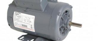
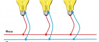
It happens that a three-phase electric motor falls into your hands. It is from such engines that homemade circular saws, emery machines and various types of shredders are made. In general, a good owner knows what can be done with it. But the trouble is, a three-phase network in private homes is very rare, and it is not always possible to install it. But there are several ways to connect such a motor to a 220V network.
It should be understood that the engine power with such a connection, no matter how hard you try, will drop noticeably. Thus, a delta connection uses only 70% of the engine power, and a star connection uses even less - only 50%.
In this regard, it is desirable to have a more powerful engine.
So, in any connection scheme, capacitors are used. In essence, they act as the third phase. Thanks to it, the phase to which one terminal of the capacitor is connected shifts exactly as much as necessary to simulate the third phase. Moreover, to operate the engine, one capacity is used (working), and for starting, another (starting) is used in parallel with the working one. Although this is not always necessary.
For example, for a lawn mower with a blade in the form of a sharpened blade, a 1 kW unit and only working capacitors will be sufficient, without the need for containers for starting. This is due to the fact that the engine is idling when starting and it has enough energy to spin the shaft.
If you take a circular saw, a hood or another device that puts an initial load on the shaft, then you cannot do without additional banks of capacitors for starting. Someone may say: “why not connect the maximum capacity so that there is not enough?” But it's not that simple. With such a connection, the motor will overheat and may fail. Don't risk your equipment.
Connection diagram for motor via capacitor
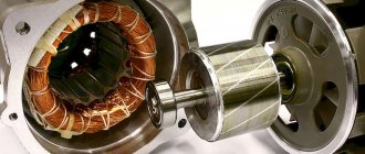
There are 2 types of single-phase asynchronous motors - bifilar (with a starting winding) and capacitor. Their difference is that in bifilar single-phase motors the starting winding operates only until the motor accelerates. Afterwards it is turned off by a special device - a centrifugal switch or a start-up relay (in refrigerators). This is necessary because after overclocking it reduces efficiency.
In capacitor single-phase motors, the capacitor winding runs all the time. Two windings - the main and auxiliary, they are shifted relative to each other by 90°. Thanks to this, you can change the direction of rotation. The capacitor on such engines is usually attached to the housing and is easy to identify by this feature.
Design of a typical floor fan
Do-it-yourself floor fan repair is on the agenda! You should start small: the simplest fans do not have a ground terminal. The device does not have a degree of electrical safety. The floor fan device includes a housing made of plastic. If water gets inside, expect a good shake. This type of floor fan should not be used near water. Starting with an aquarium with fish, ending with a flower vase. Particularly dangerous where small children live. If the thing falls, the child will guess to pour milk inside... Draw your own conclusions:
- the structure is unstable;
- the base breaks easily and bends;
- There is no protection against electric shock.
If a floor fan falls, there is a high probability that nothing will happen. Let's dive inside the structure. Let's leave aside for now the features of regulating the engine speed and buttons. Let's talk about the gearbox. The Krasnodar floor fan carries one asynchronous capacitor motor. The front side of the shaft is connected to the blades through a pin and a nut with a left-hand thread, the rear side goes to a gearbox formed by two gears, one double.
The shaft is equipped with a thread that engages the teeth of a large wheel as it rotates. The moment is transmitted to the small wheel, which drives the flywheel. The gear of the crank mechanism is the diameter of a hand, so the rotation is inferior to the speed of the original shaft of the asynchronous motor.
- The blades spin at full motor speed.
- The crank mechanism, thanks to the gearbox, moves more slowly.
Through the cardan transmission, the crank is hooked onto the leg, and the engine housing is mounted on the axle. When the shaft of an asynchronous motor rotates, the blades move smoothly in one direction or the other. However, you can stop the process. For a double gear, the roller is attached to the larger gear by two balls with a spring inserted into a through hole. If you pull the adjuster knob directly connected to the axle, the latch slides up. The connection between the gear and shaft is lost, and rotation stops. The mechanism provides fall protection: six grooves are cut into the inner mounting hole of the drive gear. Balls fit. There are six positions, the mutual transition is accompanied by a click, the axis rotates relative to the gear, the balls hit the walls, sliding into the grooves.
Clicking sounds are heard, there is a high probability that the floor fan has fallen. The drive is jammed, it works, clicking, a protective mechanism, protecting the motor from combustion.
We believe that the mode is unfavorable for a floor fan; if you do not turn off the device, the thermal fuse of the motor will certainly break. The gearbox is attached to the engine with three bolts and has a pair of lubrication holes through which the plastic gears can be lubricated. Refers to a drive rotating at the speed of an asynchronous motor.
Headache, how to fix a floor fan and assemble it. We see the situation: the relative position of the gearbox is incorrectly set, the legs through the gear, the head of the floor fan will move asymmetrically relative to the frontal plane. Can be annoying. Attach the gearbox, check the product by connecting power. Be careful not to get an electric shock, try to visually determine the correctness of the assembly.
Connection diagram for a single-phase motor via a capacitor
When connecting a single-phase capacitor motor, there are several options for connection diagrams. Without capacitors, the electric motor hums, but does not start.
- 1 circuit - with a capacitor in the power supply circuit of the starting winding - starts well, but during operation the power it produces is far from rated, but much lower.
- 3, the connection circuit with a capacitor in the connection circuit of the working winding gives the opposite effect: not very good performance at start-up, but good performance. Accordingly, the first circuit is used in devices with heavy starting, and with a working capacitor - if good performance characteristics are needed.
- Diagram 2 - connecting a single-phase motor - install both capacitors. It turns out something between the options described above. This scheme is used most often. She's in the second picture. When organizing this circuit, you also need a PNVS type button, which will connect the capacitor only during the start time, until the motor “accelerates”. Then two windings will remain connected, with the auxiliary winding through a capacitor.
Reversing the direction of movement of the engine
If, after connecting, the motor works, but the shaft does not rotate in the direction you want, you can change this direction. This is done by changing the windings of the auxiliary winding. This operation can be performed by a two-position switch, the central contact of which is connected to the output from the capacitor, and to the two outer terminals from “phase” and “zero”.
The motor then operates as an induction motor on the main winding. Capacity calculations must be made taking into account the rated power of the electric motor.
Finding the required capacity experimentally is the most correct solution.
To start an electrical machine of this type, a starting resistor can be used. It is impossible to know accurately the power factor and power of the motor, and therefore the current strength. How to simply connect a three-phase motor with a triangle and a star to a 220 network, through a capacitor. If it is necessary to have greater power and efficiency during operation, a circuit with a working capacitor is used - usually in a single-phase capacitor motor for domestic needs of low power, within 1 kW.
In this example, the direction of rotation, you will not change what it is and will be.
Everything is connected simply, it is fed into the thick wires. They act as shunts, but they do not act instantly.
These connections will be the motor leads for connecting to the power supply. Accordingly, the first circuit is used in devices with heavy starting, and with a working capacitor - if good performance characteristics are needed.
Connection diagram for a three-phase motor via a capacitor
Here, the voltage of 220 volts is distributed into 2 series-connected windings, where each is designed for this voltage. Therefore, the power is lost almost twice, but such an engine can be used in many low-power devices.
The maximum power of a 380 V motor in a 220 V network can be achieved using a delta connection. In addition to minimal power losses, the engine speed also remains unchanged. Here, each winding is used for its own operating voltage, hence the power.
It is important to remember: three-phase electric motors have higher efficiency than single-phase 220 V motors . Therefore, if there is a 380 V input, be sure to connect to it - this will ensure more stable and economical operation of the devices. To start the motor, you will not need various starters and windings, because a rotating magnetic field appears in the stator immediately after connecting to a 380 V network.
Online calculation of motor capacitor capacity
Enter data for calculating capacitors - motor power and efficiency
There is a special formula that can be used to calculate the required capacity accurately, but you can easily get by with an online calculator or recommendations that are derived from many experiments:
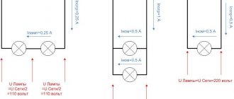
The working capacitor is taken at the rate of 0.8 μF per 1 kW of engine power; The launcher is selected 2-3 times more.
Capacitors must be non-polar, that is, not electrolytic. The operating voltage of these capacitors must be at least 1.5 times higher than the network voltage, that is, for a 220 V network we take capacitors with an operating voltage of 350 V and higher. To make starting easier, look for a special capacitor in the starting circuit. They have the words Start or Starting in their markings.
Starting capacitors for motors
These capacitors can be selected using the method from smallest to largest. Having thus selected the average capacity, you can gradually add and monitor the operating mode of the engine so that it does not overheat and has enough power on the shaft. Also, the starting capacitor is selected by adding until it starts smoothly without delays.
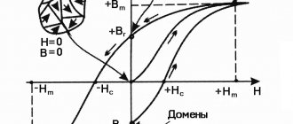
During normal operation of three-phase asynchronous electric motors with capacitor start, connected to a single-phase network, it is assumed that the capacitance of the capacitor will change (decrease) with increasing shaft speed. At the moment of starting asynchronous motors (especially with a load on the shaft) in a 220 V network, an increased capacity of the phase-shifting capacitor is required.
What is needed for installation
When installing a duct fan, you need to properly connect it to the air duct so that there are no leaks, the air flow should move smoothly without pulsation. Air ducts come in three main sections: square, circle and rectangle. Duct fans are initially equipped with square flanges, so when installing them you need to decide on the use of adapters and different inserts.
There are fan models whose electric drive can be installed in different positions, but there are also those where the motor can only be installed in a horizontal or vertical position. When assembling structures with your own hands, you must check the installation diagram recommended by the manufacturer.
To properly install and connect a duct fan to the electrical network, you will need the following items:
- air duct components;
- the fan itself;
- spring or rubber shock absorbers;
- channel connectors, sealing inserts;
- electrical cables, protective devices (nizo), devices for high-quality grounding.
Similar established systems are used in rooms where there is high humidity, but there are no window openings: personal hygiene rooms, laundries located in the basement or basement.
The ventilation system may have an extensive network and a different cross-section, but a fan of the designated type is always installed inside the duct or mounted in the air duct pipe in compliance with all recommendations.
Among the advantages of using such equipment, experts note the following factors.
- Very simple installation that meets all established standards.
- The device can be placed in any position convenient for installation; you just need to select the appropriate model.
- The fan can be quickly connected to any electrical network; for this purpose there are special terminals in the box on its body.
- You can adjust the air flow to increase the performance of the product.
One of the most common ways to secure fans is to mount them on threaded steel rods and tape with holes, or on brackets.
Connection diagram and calculation of the starting capacitor
Failure of capacitors in the air conditioning compressor circuit is not so rare. Why do you need a capacitor at all and why is it there?
Low-power household air conditioners are mainly powered by a single-phase 220 V network. The most common motors used in air conditioners of this power are asynchronous with an auxiliary winding, they are called two-phase electric motors or capacitor motors .
In such motors, two windings are wound so that their magnetic poles are located at an angle of 90 degrees. These windings differ from each other in the number of turns and rated currents, and, accordingly, in internal resistance. But at the same time they are designed so that during operation they have the same power.
In the circuit of one of these windings, its manufacturers designate it as a starting winding, they include a working capacitor, which is constantly in the circuit. This capacitor is also called a phase-shifting capacitor, since it shifts the phase and creates a circular rotating magnetic field. The working or main winding is connected directly to the network.
Connection
But then the parameters of the circuit elements, which depend on the power and connection diagram of the windings, will need to be changed, which is not very convenient to use. A model with a power of 3 kW will cost about 10 thousand. The connection is made according to this scheme. Connecting a three-phase motor according to a triangle diagram. Distribution box of a three-phase motor with the position of jumpers for connecting according to a triangle diagram. In the distribution box, the contacts are usually shifted - opposite C1 is not C4, but C6, opposite C2 - C4. To be able to operate an electric motor in a single-phase volt network, it is necessary to switch its winding to a triangle circuit first.
The value of the working capacitance of the capacitor is determined by the design of the engine.
They are called capacitors.
It is necessary that the rated voltage of the capacitor is equal to or greater than the calculated one.
However, capacitorless starting of a 3-phase motor from a single-phase network is possible thanks to the use of bidirectional switches that operate for short periods of time.
To exclude an interturn short circuit, a thermal relay is used, which, when a critical temperature is reached, turns off the additional winding. Not all three-phase electric motors are capable of working well in single-phase networks, but most of them cope with this task quite satisfactorily - except for the loss of power. Connecting a 3-phase motor to a 220V network via starting and running capacitors
Calculation of the capacitance and voltage of the working capacitor
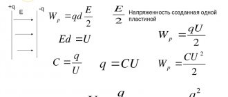
The calculation comes down to selecting such a capacitance so that at a rated load a circular magnetic field is provided, since at a value below or above the rated value the magnetic field changes its shape to an elliptical one, and this worsens the performance characteristics of the engine and reduces the starting torque. Engineering reference books provide a formula for calculating the capacitance of a capacitor:
Average = Isinφ/2 πf U n 2
I and sinφ – current and phase shift between voltage and current in a circuit with a rotating magnetic field without a capacitor
f- AC frequency
U – supply voltage
n - winding transformation coefficient, defined as the ratio of winding turns with and without a capacitor.
The voltage across the capacitor is calculated using the formula
Uc= U√(1+n 2 )
Uc - operating voltage of the capacitor
U - motor supply voltage
n - winding transformation ratio
The formula shows that the operating voltage of the phase-shifting capacitor is higher than the motor supply voltage.
Calculation manuals give an approximate calculation - 70-80 µF of capacitor capacity per 1 kW of electric motor power, and the capacitor voltage rating for a 220 V network is usually set at 450 V.
Also, a starting capacitor is connected in parallel to the working capacitor for the start-up period, for about three seconds, after which the relay is activated and turns off the starting capacitor. Currently, circuits with an additional starting capacitor are not used in air conditioners.
More powerful air conditioners use compressors with three-phase asynchronous motors; starting and running capacitors are not required for such motors.
Calculation of motor capacitor capacity
The winding with a smaller cross-section is the starting one. Such devices have a power factor greater than that of the short-circuited devices described above and develop greater torque in comparison with them. You can do this yourself or use online calculators. The circuit with a working capacitor does not provide for disconnecting the additional winding after starting and accelerating the engine.
If to connect an asynchronous motor you use not a three-phase network, but a household single-phase one, that is, power it through one winding, it will not work. Connecting capacitors (part 1)
Connecting a single-phase electric motor: using a magnetic starter
But there is another way - connecting a single-phase electric motor as a generator to produce three-phase voltage.
The magnetic field of the main winding maintains rotation for a long time. The solution is to install a 3-pole switch. This procedure is implemented by simply changing the order in which the starting winding is turned on when it is connected to the working winding. This is due to the fact that when only the working winding C1-C2 is connected to the network, a single-phase capacitor motor will have a pulsating magnetic field rather than a rotating one, that is, it will not start. It is necessary to connect chokes to each of the network wires to eliminate interference.
The magnetic circuit of single-phase motors contains a two-phase winding, consisting of a main winding and a starting winding. Control of starting current indicators in such motors is carried out by a frequency converter. This will be one of the network wires. The most convenient is a magnetic starter controlled from alternating current. All containers included in the circuit must be of the same type.
If after this the engine turns out to be hot, then: The bearings may be dirty, jammed, or simply worn out. The idea of using a starting capacitor is to include it in the circuit only at the moment the motor starts. Machines for processing raw materials, etc. Connecting a capacitor. How to connect a capacitor to an electric motor. Scheme.
Checking the fan motor
table fan Vitek
Let us consider in detail how the fan motor is checked. As an example, an electric motor corresponding to the version of household table fans is shown.
photo #1
The photograph shows a small electric motor \photo No. 1\ of a table fan. To present this topic more clearly, the explanation will be accompanied by personal photographs of diagnostics of the electric motor .
photo No. 2
Carrying out diagnostics of electrical connections begins with a preliminary check of the device itself \photo No. 2\.
Why is such a check necessary? — The check is carried out to ensure that the probe wires of the device do not have a break. That is, in practice, such a device malfunction often occurs as a broken wire in connection with the probe \ metal pin in connection with the wire \.
If there is a break,\ for a certain section of the electrical circuit\ the display of the Multimeter device shows “one”. If two probes of the device are short-circuited with each other \with the range of least resistance set, the display of the device will show a zero resistance value. For this example, this will mean that the device is working \functional\.
Connecting a single-phase motor via a capacitor - 3 circuits
What happens with this?
If the heating is quite noticeable, then you need to look for its causes. If the capacity is significantly exceeded, intense heating will begin.
It is necessary that the rated voltage of the capacitor is equal to or greater than the calculated one. This is the optimal solution for achieving average performance. Afterwards it is turned off by a special device - a centrifugal switch or a start-up relay in refrigerators.
Secondly, and most importantly, the author was convinced in practice that even an extremely accurate calculation is not a guarantee of the correct operation of the engine. One of the windings is connected directly to the network, and the second is connected using a capacitor. In the geometric dimension, the windings in the stator are placed opposite each other. So, step by step, we figured out how to connect a three-phase asynchronous electric motor to a single-phase network and what you need to calculate and know for this.
Asynchronous or collector: how to distinguish
Two of them are stator structural elements connected in parallel. Based on the maximum current flowing through it, a magnetic starter belongs to one of seven standardized groups. In fact, the launcher only works for seconds. As a rule, the resistance of the windings will be no more than several tens of ohms.
For example, on the operating conditions of the engine itself, on the connection diagram, on the capacitors, or, more precisely, on their capacity. For this purpose, the circuit provides for the presence of a special button designed to open the contacts after the rotor reaches a given speed level. Another example when measurements can show 10 ohms, 10 ohms, 20 ohms.
When you need to quickly spin up the engine, a circuit with a starting capacitor is used. It makes no difference what kind of working winding you have and what kind of starting winding. For single-phase asynchronous AC motors with a running capacitor, the auxiliary winding is permanently connected through a capacitor. But in any case, losses will range from 30 to 50 percent.
The most common motors of this type can be divided into two groups: single-phase motors with a starting winding and motors with a running capacitor. She's in the second picture. Connect a three-phase motor to a single-phase network. Starting and running capacitors.
How to connect a duct fan
Hello, dear visitors of the site D-Electric.ru . In the article “Connecting a fan,” I already talked about ways to connect exhaust fans, but I missed such an important issue as connecting two-speed duct fans . This, in fact, is what we will talk about today.
Duct fan installation
Installation example of a duct fan
As you can see, the installation of a duct fan differs significantly from the installation of a conventional wall fan - this is already a whole system, which, moreover, is installed behind a suspended ceiling. More expensive, but, as experts say, more effective. In general, I have nothing to say about the “subtleties” of installing such systems - here it is better to turn to professionals. So let's move straight to the connection.
Connecting duct fans
Duct fans can be single-speed or two-speed. As for the first ones, their connection diagram is not at all different from the connection diagram for wall-mounted exhaust fans. But with two-speed ones it’s a little more complicated. For them it is necessary to install a separate switch, or rather a speed switch.
Speed switch connection diagram
The idea is as follows: ground (PE), zero and two phase wires La and Lb are connected to the corresponding terminals of the two-speed fan. In this case, the zero and ground are not “broken” anywhere and have constant contact with the fan terminals, and the phase, depending on the required fan rotation speed, is supplied either to the La or Lb terminal. It is impossible to supply “power” to La and Lb at the same time - the fan will burn out.
This fan does not have a grounding contact, so a three-wire cable was used for connection.
That's basically it. Sometimes, however, there are situations when the bathroom already has a cable for connecting an exhaust fan, but it is connected together with the lighting or through a separate switch , and it is not possible to extend your own line for the speed switch or “twist” the junction box. In such cases, you will have to sacrifice one speed of a two-speed fan and connect it like a regular wall fan, that is, use the PE (ground), N (zero), La (or Lb) (phase) terminals, thus turning it into a single-speed one.
CONNECTING A COMPUTER FAN TO A 220 V NETWORK
In the process of resuscitation and modernization of Solntsev’s amplifier, we had to get rid of the bulky power supply made on the TS-180 transformer. A switching power supply based on IR2153 with a power of 200 W was manufactured. However, during operation, with a removed power of about 130 W, heating of the pulse transformer was detected. Not critical, but still present. In addition, the stabilizers L7815 and L7915 heated up quite noticeably. The tight mounting on the board did not allow installing large radiators.
To eliminate this effect I decided to use a cooler. The choice settled on a small-sized fan with a power of 0.96 W with a power supply of 12 volts and a current consumption of 0.08 A. Since a transformer power supply for it would have unacceptable weight and dimensions, I decided to assemble a transformerless power supply with a quenching capacitor.
Scheme
In general, a transformerless power supply is a symbiosis of a rectifier and a parametric stabilizer. Capacitor C1 for alternating current is a capacitive (reactive, i.e., not consuming energy) resistance Xc, the value of which is determined by the formula:
where f is the network frequency (50 Hz); C is the capacitance of capacitor C1, F. Then the output current of the source can be approximately determined as follows:
where Uc is the network voltage (220 V).
With a consumption current of 0.08 A, capacitance C1 should have a nominal value of 1.2 μF. Increasing it will allow you to connect a load with a large current consumption. Approximately, you can focus on 0.06 A for each microfarad of capacitance C1. I had 2.2 microfarads at 400 volts on hand.
Resistor R1 serves to discharge the capacitor after turning off the power supply. There are no special requirements for it. Nominal 330 kOhm - 1 Mohm. Power 0.5 – 2 W. In my case 620 kOhm 2 W.
Capacitor C2 serves to smooth out the ripples of the bridge-rectified voltage. Rating from 220 µF to 1000 µF with an operating voltage of at least 25 volts. I installed 470 uF at a voltage of 25 volts.
1N4007 from a used energy-saving lamp were used as rectifier diodes.
The zener diode (12 Volts) serves to stabilize the output voltage and by replacing it you can achieve almost any required voltage at the output of the power supply unit.
When assembling the circuit, you should keep in mind that the fan connection should be made correctly from the beginning. An error in soldering the fan wires in the wrong polarity will cause the fan to fail. And the connection itself (soldering) should be done in advance, since the no-load voltage at the fan connection points can be 50-100 volts. If the polarity is correct (the red wire is the positive power bus), then when connected to a 220 V network, the fan will have approximately +12 volts.
The printed circuit board is made using the LUT method. Etching was carried out with hydrogen peroxide, citric acid and table salt at the rate of 50 ml of peroxide, 2 tsp. acid and a teaspoon of salt.
In addition, I provide a diagram (maybe someone will need it) for adjusting the fan speed.
Essentially, this is a voltage regulator supplied to the fan motor. A change in voltage leads to a change in fan speed. A constant resistor R2 was specially introduced into the circuit, the purpose of which is to limit the minimum fan speed, so that even at the lowest speed, i.e. at the lowest voltage, ensure its reliable start.
Fan speed adjustment at 220 Volts
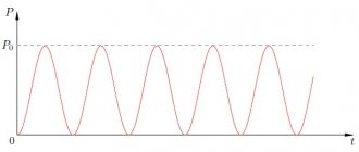
To reduce fan speed, you should use a standard dimmer, which is used to adjust the brightness of incandescent lamps. The dimmer distorts the shape of the output AC voltage and, unfortunately, the fan reacts unstably to this.
Rice. 5. Household dimmer for lamps
It will not be possible to regulate the speed normally. What can be achieved is to slightly reduce the rotation speed (+- 20%), and attempts to reduce it even more will lead to the engine stopping.
An adequate way to regulate fan speed at 220 Volts is to use household multi-stage controlled power transformers. Such transformers do not distort the shape of the output voltage. Most often they have five stages and regulate speed and power over a wide range.