Capacitors are devices that store electrical energy in the form of charges. The devices cannot pass direct current through themselves. Being connected to a circuit with alternating current, it is likened to a spring subjected to external influence. It is noteworthy that they will not allow current to pass through, but when it passes, the drive will recharge, which will make it seem like it is passing through the plates. If a constant voltage is applied to them in a discharged state, then a current will flow through the circuit, which decreases as the drive charges. When voltage parity is reached between the power supply and the plates, it stops flowing, causing a rupture.
What is a capacitor
Capacitors are passive elements used in the formation of various electrical circuits, blocking and protective devices. When connected to an alternating circuit, the storage device accumulates and returns energy. If an AC is connected, then the energy is returned to the system, while maintaining a periodicity that corresponds to the operating frequency.
What are capacitors
For your information! When alternating current flows through a capacitor, it continuously provides resistance, the magnitude of which is inversely proportional to frequency.
A decrease in frequency leads to an increase in resistance. When a source generating such current is connected to a storage device, the maximum voltage is determined by the strength.
To use an example to verify the possibility of conducting alternating current, a simple electrical circuit is formed, including the following components:
- variable sources;
- capacitor;
- the consumer is usually a light bulb.
Circuit with a capacitor
Being included in a variable, the capacitor is recharged from time to time, acquiring and releasing charges. Consequently, electricity is exchanged between the source and the two-terminal network, which leads to the formation of reactive energy.
Note! The device does not allow transmission through a permanent network, since in this case the existing resistance will be equal to infinity. If a variable passes through, then the resistance will have a finite value.
Principle of operation
The capacitor can be made in different ways, but the essence of the work and its main elements remain unchanged in any case. To understand the principle of operation, it is necessary to consider its simplest model.
The simplest device has two plates: one of them is positively charged, the other, on the contrary, negatively. Although these charges are opposite, they are equal. They attract with a certain force, which depends on the distance. The closer the plates are to each other, the greater the force of attraction between them. Thanks to this attraction, the charged device does not discharge.
However, it is enough to lay any conductor between the two plates and the device will instantly discharge. All electrons from the negatively charged plate will immediately transfer to the positively charged one, resulting in equalization of the charge. In other words, to remove the charge from the capacitor, you only need to short-circuit its two plates.
Operating principle of a capacitor
Connecting the device to a constant source leads to the fact that at the initial moment there is an accumulation in the plates due to electrostatic induction, and the resistance at this moment is equal to zero. Electrical induction provokes a field to attract opposite charges onto different plates located opposite each other.
You might be interested in The simplest asynchronous current generator
This property is called capacitance, which is characteristic of all types of materials, including dielectrics, but in the case of conductors it is significantly greater. That is why the plates are made of conductor. An increase in capacity contributes to the accumulation of more charges on the plates.
Important! When charges accumulate, the field weakens and the two-terminal network increases.
Principle of operation
This happens due to a decrease in space in the plates and the influence of charges of the same name on each other. At the same time, the voltage is equal to the current source. The cessation of electricity in the circuit occurs after the plates are completely filled with electricity. Because of this, induction disappears and only a field remains that holds and does not allow charges to pass through.
Dielectric between plates
The electric current will have nowhere to go, and on a two-terminal network the voltage is equal to the EMF. When the EMF increases, the field acts more strongly on the dielectric due to the lack of space in the plates. If the internal capacitor voltage is higher than the limit values, then the dielectric will break through.
The capacitor is converted into a conductor, and charges are released, causing an electric current to flow. To use a two-terminal network at high voltage, increase the size of the dielectric and increase the distance between the plates while reducing the capacitance. The dielectric is located between the plates and does not allow the constant to pass through, performing a barrier function in relation to it.
Electrical induction
Note! It is direct voltage that can form electrostatic induction, but only in the case of a short circuit at the time of charging the capacitor. Thanks to this mechanism, energy is saved until the consumer is connected to it.
Capacitor in DC circuit
To understand how a storage device works in a DC circuit, you need to add a light bulb to the circuit, which will light up only during charging, during which the voltage remains from the electric current, as if catching up with it due to a smooth increase. Charges of electricity take some time to move to the plates; this is precisely the charging time, the duration of which is determined by the frequency and voltage capacitance. When charging is complete, the light goes out and no constant current flows through the passive electronic component.
Capacitor in AC circuit
If the polarity of the source is changed, this will lead to the discharge of the capacitor in the alternating current circuit and its recharging. A constant electrostatic induction is formed with an alternating one. Whenever electricity changes its direction, the charging and discharging mechanism is triggered, which is why it passes the variable. An increase in frequency leads to a decrease in the capacitive reactance of a two-terminal network.
You may be interested in: Installation and connection of heated floors
Capacitor in a constant circuit
Electronics for everyone
So, we figured out the wiring, current, and sources. Now let's go over the elements. Now I will push the cart about the capacitor. How does current flow through it if it is an open circuit?
We put on the plumber's overalls and rush into the storage room to get the pipes, we will make a model of a capacitor from shit and sticks. In order not to stand out from the sewer style.
What is a capacitor? From a physics textbook we know that these are two conductor plates, and between them there is a thin dielectric; the thinner it is, the better the capacitor. Well, this is the garbage we are making from pipes. We will also need a king size condom, which will work for the dielectric. And what? It does not let water through, it will do! Let's connect two pipes and put a membrane between them. Hermetically closing the duct, but very elastic.
Doesn't it look like it happened? In a capacitor, energy is stored in an electric field, and in our case, energy will be stored in the elastic element of the membrane from a condom. The greater the pressure, the more the membrane stretches. Sooner or later, the pressure of the source will be balanced by the counteraction of the membrane and the process will stop. But you can always add more pressure and it will stretch even more. And again, and again, and again until it bursts. We neglect the volumes of the chamber where the membrane can rest.
With an electric capacitor the situation is completely similar. When we apply voltage to it, it charges. An electric field arises inside it, which balances the voltage of the source. But if we increase the voltage, the capacitor will be recharged. And again, and again, until it breaks through. An ideal capacitor can be charged indefinitely, increasing the voltage indefinitely. But let’s leave these delights to the mathematicians, they love all these theoretical jokes.
So how does it conduct current? After all, if we put it in a circuit and turn it on, then at best our load will twitch a little, and then the capacitor will charge and that’s it. Everything will fall into place
But it will twitch! Let's replace the DC source with an AC source. Let's make it from a piston and crank:
In! Now the liquid will swing back and forth. The capacitor membrane will stretch in one direction and then in the other. The fluid will move in the pipe, and energy will begin to be transferred from the source to the load - the impeller at the other end of the pipe. You just need to straighten it there with some kind of ratchet wheel and you're done. And, most importantly, the capacitor separating the pipe is no longer a hindrance at all. The alternating flow passes through it perfectly.
In an electric Conder the situation is completely similar. Of course, the capacitor resists the current and it also has resistance. It is called reactance Xc and depends on frequency.
C - here the capacitance of the capacitor f - frequency
Direct current has a frequency = 0, therefore the reactance of the capacitor at direct current is equal to infinity, an open circuit. And the higher the frequency, the lower the resistance.
Now remember that a capacitor is any two conductors separated by a dielectric. ANY. Are two parallel tracks on the board conductors? Without a doubt. Separated by a dielectric? Certainly! Which means... That’s it! True, capacitive couplings usually do not bother, because The capacity there is usually small. But, if our circuit begins to operate at a high frequency, then the resistance of these capacitive connections decreases sharply and they begin to influence. Therefore, the design of truly high-speed devices, where frequencies are in gigahertz and higher, is still black magic. Because there you have to take into account all these parasitic effects and a bunch of others.
Now let’s suddenly apply water, aka current, and see what we get in dynamics.
Point in time 1.
Our capacitor is not charged, there is nothing in it, the membrane is relaxed. The pipe is blocked by a valve.
Point in time 2.
They opened the damper and the flow rushed into the condenser. The pressure in the pipe in front of it is zero. Why should he be big? The water flows in calmly, without any resistance. But the fluid flow rate is maximum. It’s as if there is no barrier here, as if everything is short-circuited. I drew the flow speed with arrows; the longer the arrows, the greater the speed. I indicated the flow pressure by the thickness of the arrow. The thinner the arrow, the greater the pressure, as if it is being flattened by pressure.
Point in time 3.
The capacitor has not yet fully charged, but the membrane has already begun to stretch and provide resistance. The flow rate decreases and the voltage increases.
Point in time 4.
The capacitor is fully charged, its membrane is stretched and, with its elasticity, completely compensates for the pressure that the source develops. The inlet pressure became equal to the source pressure. It was as if the capacitor had become a dead end. Flow velocity is zero.
Its electric counterpart behaves exactly the same. When the capacitor is not charged, its voltage is zero, it does not resist the flow of current, so the current is maximum. As charging occurs, the voltage increases, but the current decreases. And, as a result, the current becomes equal to zero, and the voltage is equal to the source.
Here we come to one fundamental concept in TOE - the phase shift between the current and voltage on the capacitor. In a capacitor, the current leads the voltage. This is what it looks like:
Let's turn on our alternating sinusoidal voltage generator at time 0. The current immediately breaks to the maximum, the capacitor is discharged, pour in! And the voltage will be lagging by a quarter of the period, i.e. 90 degrees, grow behind it. Then the condenser will charge, the voltage will finally reach its maximum, and the current will drop to zero. But at this moment the generator will change polarity and the capacitor will begin to discharge, the current will increase again, but in the opposite direction, and the voltage will correspondingly fall - the capacitor is then discharged, and current flows from it. And so on until the entire system reaches a mirror opposite state. When the capacitor is fully charged in the opposite direction, and then the generator changes polarity again...
From here it is worth remembering the following rough theses.
- 1. A discharged capacitor behaves like a short circuit.
- 2. A charged capacitor behaves like an open circuit.
- 3. In the interval between states 1 and 2, a charging capacitor can be represented as a resistor whose resistance rapidly increases from zero to infinity, exponentially.
- 4. A discharging capacitor behaves as a voltage source whose voltage drops with discharge.
- 5. The capacitor passes alternating current, the higher the frequency, the lower the resistance of the capacitor.
- 6. No matter how charged the capacitor is, it can always be recharged by applying voltage from above. If only it didn't break through.
- 7. Due to the current advance of the capacitor, the maximum current coincides with the minimum voltage and vice versa.
This will allow you to speculatively estimate the operation of most circuits with capacitors. Now I will support these theses with examples.
▌A discharged capacitor behaves like a short circuit
This is why, for example, the pins of microcontrollers connected directly to powerful power MOSFET switches burn out, because their gates have a noticeable capacitance and until it is charged, the controller pin actually operates on a short circuit.
For the same reason, the contacts of relays and buttons operating on a capacitive load may burn out. Because at the moment the capacitor is charged, a current flows through its circuit that is actually equal to the short circuit, albeit for a very short time. But the contacts are not designed for such a current.
▌A charged capacitor behaves like an open circuit
Many timing circuits are built on this principle. The simplest example is the reset circuit of a microcontroller.
At the initial moment of time, the capacitor behaves like a short circuit and closes the reset to ground or to power, depending on how it is turned on. And then, when the capacitor is charged through the resistor, it turns into an open circuit and the output is pulled to the opposite level by the resistor. A reset signal is obtained.
All sorts of pulse current limiting circuits are built on a similar principle. Like this one for example:
The relay has an operating current, the minimum current value to break the armature from its place. And the holding current is the minimum current value at which the armature is securely held and does not fall off. The operating current is much greater than the holding current. And if this worries us, if we want to reduce the current that our relays consume (and if there are many dozens of them, then the current can be large), then we can put a resistor bypassing it with a capacitor. Then at the moment of start, the capacitor will be discharged and similar to a short circuit, this will give a jerk that will pull the armature from its place. And then the capacitor will charge, turn into an open circuit, and all the current will flow through the current-limiting resistor. Significantly reducing consumption. Here we really need to take into account the category. If the relay clicks constantly, then the capacitor may not have time to discharge, and the holding current will not be enough to turn it on.
▌A charging capacitor can be thought of as a resistor whose resistance rapidly increases from zero to infinity, exponentially.
This is of course not entirely true, but nevertheless, what prevents us from thinking so? How can it be applied? Well, for example, make a “voltage divider”, where the lower arm will not be a resistor, but a capacitor. At the output, when turned on, there will be a smoothly increasing (more precisely exponentially) voltage, as if we had inserted a variable resistor with an exponential dependence instead of a capacitor and twisted it from zero to infinity. Let's get, for example, a control signal for smooth ignition of the light.
▌A discharging capacitor behaves as a voltage source whose voltage drops with discharge
Well, I don’t think there’s much need to explain here. Everyone has seen huge scatterings of capacitors in good power supplies. Sometimes they are so huge that even if you unplug the device from the socket, it can still work for a few seconds on the energy stored in the condensers. There, the capacitors simply stand in the power bus between plus and minus and serve as energy storage devices to smooth out power failures.
▌The capacitor passes alternating current, the higher the frequency, the lower the resistance of the capacitor
This is the main theme of all filters. By shortening the capacitors, we either drain unnecessary frequencies to ground or do not allow them to pass further. Or both at the same time. Depending on what we need.
According to Fourier's theorem, a periodic signal can be represented as a sum of sinusoids-harmonics with different amplitudes and frequencies. Using a filter, you can suppress unnecessary harmonics.
▌No matter how charged the capacitor is, it can always be recharged by applying voltage from above. If only it didn't break
Based on this principle, various decoupling capacitors are used to separate the DC component from the variable component. A common theme for audio equipment.
Let's return to our pipe with a membrane. Let’s just add to the AC voltage source a much more powerful DC one. The initial flux fluctuation will be the sum of them. On a positive wave of an alternating source, the pressure will be added, and on a negative wave it will be subtracted. But because a constant is more powerful, it will provide displacement.
Let's wrap this structure into our pipe. What will happen? The displacement will immediately tighten the membrane and this will limit its effect. And variable fluctuations will either stretch it further or weaken it. Those. Only the oscillations of the variable source will go to the load, while the constant source will be cut off by a capacitor.
Everything is the same in the electrical circuit. For example, we have a certain audio frequency power amplifier. But the trouble is, its output is not pavement and can only fluctuate from zero to maximum, without going into minus. Moreover, the offset there is several volts. If we connect a speaker, then this displacement will stretch the magnetic system to one side to the limit and at best it will wheeze sluggishly. Otherwise the scribe will spit out the reel and give it to him.
We plug in a blocking capacitor and the problem is solved. All the DC voltage will land on this capacitor, and only its variable part, which makes up sound vibrations, will go to the speaker.
For exactly the same circuit, blocking capacitors are placed between the amplifier stages. In order for each subsequent transistor to work only with the variable component of the signal, without a blocking capacitor, the constant component will immediately drive the transistor into saturation and it will stop perceiving any fluctuations in the control signal at all.
▌Due to the current advance of the capacitor, the maximum current coincides with the minimum voltage and vice versa.
This principle is used, for example, in a capacitor power supply. After all, in fact, it is a banal voltage divider, but operating on alternating current.
But what prevents us from simply making the same voltage divider using resistors? The principle is the same, but the resistor works the same everywhere. So yes, nothing really interferes. Except for losses.
A voltage divider is just a load working on the network. Converting energy into heat. If we make it high-resistance in order to reduce the current and, accordingly, losses (and our losses increase with the square of the current), then the resulting voltage source will have a very high internal resistance and will not be able to power any serious load without sagging. And if we reduce the values of these resistors, we will also reduce the internal resistance of the source, but the losses on these same resistors will increase sharply. And this is heating, these are dimensions. In short, the game wouldn't be worth the trouble.
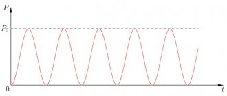
And here a capacitor comes to the rescue. He has such a joke that the maximum current amplitude coincides with the minimum voltage amplitude, and vice versa. Those. already instantaneous losses P = U*I will be less than that of a resistor. Where is the maximum current, then the maximum voltage. One to one.
▌Selection
If you don’t delve into the jungle of characteristics (and there are plenty of them, including dielectric losses, accuracy, ESR of all sorts), then the choice of a capacitor is based on two parameters - the maximum breakdown voltage and capacitance.
The maximum voltage should not be lower than what is running in your circuits. Higher is possible, lower is not possible. Therefore, it is quite acceptable to change a capacitor with a voltage tolerance of 16 volts to a 36 volt one if their capacitance is the same.
Some other capacitors, such as tantalum and electrolytic ones, have polarity. For them, everything is true as for any other capacitor, except for one thing - it cannot be charged in reverse polarity - it will die.
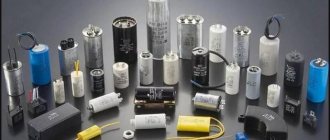
Typically, in amateur radio practice, three types of capacitors are used.
1) Electrolytic. These are barrels of different sizes. Be sure to sign where there is a minus. Capacitance and maximum voltage are indicated. They are usually included in food. They are very cheap, have a large capacity (up to hundreds of thousands of microfarads), but other characteristics are extremely bad. But for rough tasks, such as power supply insurance against drawdown or long interval tasks, they are quite suitable. They work poorly at high frequencies (due to high parasitic inductance). So they do a poor job of filtering out RF interference in the power supply.
2) Ceramic. They are cheap, work well at high frequencies, and can withstand high voltages (for their size). But they have small capacity. Up to units of microfarads. There are probably higher ones too, but the price increases very sharply with increasing capacity.
3) Tantalum. Almost everyone is good. Small, large capacity, good performance, stability and durability. But they are expensive and rare tantalum takes on more than 50 volts. And if he doesn’t like something, he naturally explodes. Moreover, there are a lot of reasons for the explosion: the polarity is reversed - boom! You charge too quickly - boom! You pump in too much current - boom! Too much tension - boom! He has an explosive character, a straight Shahid Conder.
In addition to all this, there are about 30 types of different types of capacitors, but these are rather highly specialized things and are used much less frequently than the main three.
To the heap, if you haven’t read it, here’s my last article about capacitors from the same series, because repetition is the mother of teaching:
Capacitor and RC circuit
There is a little more adequate theory (for example, you will learn how and what the rate of charging a capacitor depends on), formulas and a couple more examples. On this note, I conclude the next chapter of the electrical engineering course for children and housewives. Sincerely, Captain Obvious
Why does alternating current flow through a capacitor?
A capacitor is a discontinuity because its pads do not touch each other due to the presence of a dielectric between them that does not conduct direct current. However, being connected to a permanent circuit, it can still conduct it at the moment of connection, since charging or recharging occurs.
When the transient process is completed, current stops flowing through the passive electronic component due to the separation of its plates by the dielectric. Being connected to such a circuit, it conducts its oscillations due to cyclic recharging. Here the device enters the oscillatory circuit and, together with the coil, performs the function of an energy storage device.
This symbiosis promotes the conversion of electricity into magnetic energy or, conversely, at an equal frequency rate, which is calculated by the formula: omega = 1 / sqrt(C × L).
Why is there alternating current?
The reality is that a capacitor is not capable of passing alternating current through itself. First, he accumulates it on the covers. A situation arises in which there is an excess of electrons on one of them, and on the other, there are few of them. As a result, the capacitor gives up these charges, due to which the electrons in the external circuit move in one direction and the other from one plate to another.
For your information! The result is that electrons move within the external circuit, but not in the passive component itself. The energy is redistributed within the field between the capacitor plates, which is called displacement currents, which differ from conduction currents.
Purpose and functions of capacitors
The capacitor plays a huge role in both analog and digital technology. They are electrolytic and ceramic, and differ in their properties, but not in their overall concept. Examples of using:
- Filters high-frequency interference;
- Reduces and smoothes pulsations;
- Separates the signal into constant and variable components;
- Accumulates energy;
- Can be used as a voltage reference;
- Creates resonance with the inductor to amplify the signal.
Examples of using
In amplifiers they are usually used to protect subwoofers, power filtering, thermal stabilization and separation of DC and AC components. And electrolytic ones in autonomous circuits with microcontrollers can provide power for a long time due to their large capacity.
In this circuit, transistor VT1 is constantly open to amplify the sound without distortion. But if the input gets stuck or a direct current flows into it, the transistor will open, go into saturation and overheat. To prevent this, you need a capacitor. C1 allows you to separate the constant component from the variable. The alternating signal easily passes to the base of the transistor, but the constant signal does not.
C2, together with resistor R3, performs the function of thermal stabilization. When the amplifier is running, the transistor gets hot. This may introduce distortion into the signal. Therefore, resistor R3 helps maintain the operating point when heating. But when the transistor is cold and stabilization is not required, a resistor can reduce the power of the amplifier. Therefore, C2 comes into play. It conducts the amplified signal through itself by shunting a resistor, thereby not reducing the rated power of the circuit. If its capacitance is lower than designed, it will begin to introduce phase distortion into the output signal.
For the scheme to work well, good nutrition is a must. When a circuit consumes more current at peak values, it is always a heavy load on the power supply. C3 filters power interference and helps reduce the load. The larger the capacitance, the better the sound, but up to certain values, it all depends on the circuit.
And the power supplies use the same principle as in the previous power supply scheme, but here the capacity is needed much more. In this circuit, the capacitance of the electrolyte can be either 1000 μF or 10,000 μF.
You can also connect ceramic capacitors in parallel to the diode bridge, which will bypass the circuit from high-frequency interference and noise from the 220 V network.
Formulas for calculating current in a capacitor
The capacitance of a capacitor connected to an alternating current circuit is calculated by the formula: C = q / U, where:
- C - capacity;
- q is the charge of one of the plates;
- U is the voltage inside.
Capacitance
Capacitors come in different shapes, so they are calculated using several formulas:
- flat - C = E × E0 × S / d;
- cylindrical - C=2 π × E × E0 × l / ln(R2 / R1);
- spherical - C = 4 π × E × E0 × R1 × R2 / R2 - R.
Note! The resistance in a variable circuit that a resistor connected to an electrical circuit can provide cannot be calculated, since it is considered infinitely large. However, in this case, this can be done using the formula: Xc = 1 / 2πvC = 1 / wC.
You might be interested in Features of 220 V electric motors
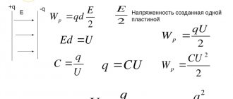
The capacitor voltage in an AC circuit is calculated using the following formula: Wp = qd E / 2.
The voltage is calculated using a certain formula
To calculate the voltage across a capacitor in an AC circuit, you need to use current formulas.
Features of connecting several capacitors in a circuit
The connection of several capacitors to each other can be series or parallel.
Sequential
A series connection allows you to apply more voltage to the plates than to a separate part. The voltage is distributed depending on the capacity of each drive. If the capacitances of the parts are equal, then the voltage is distributed equally.
The resulting capacitance in such a circuit is found by the formula:
Commun = 1/(1/С1+1/С2…+1/Сn)
If you carry out calculations, it will become clear that an increase in voltage in the circuit is achieved by a significant drop in capacitance. For example, if two 10 µF capacitors are connected in series in a circuit, the total capacitance will be only 5 µF.
Parallel
This is the most common method in practice to increase the total capacitance in the circuit. A parallel connection allows you to create one large capacitor with the total area of the conducting plates. The total capacity of the system is the sum of the capacities of the connected parts.
C total = C1+C2+…+Cn
The voltage on all elements will be the same.
Where and why are capacitors used?
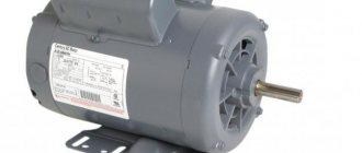
Where and why are these devices, which can operate in radio engineering, electronic and electrical devices, used? Drives are used in electrical engineering when switching on asynchronous motors for phase shifting, without which the motor as part of a single-phase circuit will not function. If the capacity is several farads, then they are used in electric vehicles to power the motor.
Application possible in various fields
Proper use of these devices will allow you to get the best results. Understanding the basic principles of physics makes operating equipment easier. Incorrect use is fraught with negative consequences caused by non-compliance with safety precautions.
Types and classification of capacitors
Different types of capacitors are adapted to different operating conditions, are aimed at performing specific tasks and have various side effects.
The main feature by which a capacitor is classified is the type of dielectric. It is the dielectric material that determines many of the characteristics of a capacitor.
Electrolytic capacitors
In electrolytic capacitors, the anode is a metal plate, the dielectric is an oxide film, and the cathode is a solid, liquid or gel-like electrolyte. The presence of a gel-like electrolyte makes the device polar, meaning current can only flow through it in one direction. Representatives of this family are aluminum and tantalum capacitors.
Aluminum electrolytic capacitors have a capacity from 0.1 to several thousand microfarads. They are usually used at audio frequencies. The electrochemical cell is tightly packed, which provides high effective inductance, which prevents the use of aluminum storage devices at ultra-high frequencies.
In tantalum capacitors, the cathode is made of manganese dioxide. The combination of the significant surface area of the anode and the dielectric characteristics of tantalum oxide provides a high specific capacitance (capacitance per unit volume or mass of the dielectric). This means that tantalum capacitors are much more compact than aluminum capacitors of the same capacity.
Tantalum capacitors have their disadvantages. Devices of early generations are prone to failures and fires are possible. They can occur when too high an inrush current is applied, which changes the structural state of the dielectric. The fact is that tantalum oxide in an amorphous state is a good dielectric. When a large inrush current is applied, tantalum oxide changes from an amorphous state to a crystalline state and turns into a conductor. Crystalline tantalum oxide further increases the current strength, which leads to fire. Modern tantalum capacitors are produced using advanced technologies and practically do not fail, do not swell, and do not catch fire.
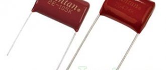
Film and metal film capacitors
Film capacitors have a dielectric layer of polymer film located between layers of metal foil.
Such devices have a small capacitance (from 100 pF to several μF), but can operate at high voltages - up to 1000 V.
There is a whole family of film capacitors, but all types are characterized by small capacitance and inductance. Due to their low inductance, these devices are used in high-frequency circuits.
The main differences between capacitors with different types of films:
- Capacitors with a dielectric in the form of a polypropylene film are used in circuits that place high demands on temperature and frequency stability. They are suitable for power supply systems, EMI suppression.
- Capacitors with a dielectric in the form of a polyester film are low cost and can withstand high temperatures when soldering. Frequency stability, compared to polypropylene types, is lower.
- Capacitors with a dielectric made of polycarbonate and polystyrene film, which were used in old circuits, are no longer relevant today.
Ceramic capacitors
Ceramic capacitors use ceramic plates as the dielectric.
Ceramic capacitors have a small capacitance - from one pF to several tens of microfarads.
Ceramics have a piezoelectric effect (the ability of a dielectric to polarize under mechanical stress), so some types of these capacitors have a microphonic effect. This is an undesirable phenomenon in which part of the electrical circuit picks up vibrations, like a microphone, which causes interference.
Paper and metal-paper capacitors
Paper, often oiled, is used as a dielectric in these capacitors. Devices with oiled paper are larger in size. Models with non-oiled paper are more compact, but they have a significant drawback - they increase energy losses under the influence of moisture, even in sealed packaging. Lately, these parts are rarely used.
More information about types and analogues of capacitors
Design and operating principle
The simplest capacitor is two metal plates separated by a dielectric. The air space between the plates can act as a dielectric. A model of such a device is shown in Fig. 2.
Rice. 2. Model of the simplest capacitor device
If a constant voltage is applied to the structure, a short-term closed electrical circuit is formed. Charges will be concentrated on each metal plate, the polarity of which will correspond to the polarity of the applied current. As charges accumulate, the current will weaken, and at a certain point the circuit will break. In our case, this will happen at lightning speed.
When a load is connected, the accumulated energy will flow through the load element in the opposite direction. There will be a short-term surge of electric current in the formed circuit. The amount of accumulated charges (capacity, C) directly depends on the size of the plates.
The unit of measurement of capacitance is usually called the farad (F). 1 F is a very large value, so in practice multiple values are often used: microfarads (1 μF = 10-6 F), nanofarads (1 nF = 10-9 F = 10-3 μF), picofarads (1 pF = 10-12 F = 10-6 µF). The milifarada value is very rarely used (1 mF = 10-3 F).
The designs of modern capacitors differ from the model we are considering. In order to increase the capacity, instead of plates, plates made of aluminum, niobium or tantalum foil separated by dielectrics are used. These puff strips are tightly rolled into a cylinder and placed in a cylindrical housing. The principle of operation is no different from that described above.
There are also flat capacitors, structurally consisting of many thin plates, pressed between layers of dielectric in the shape of a parallelepiped. Such models can be imagined as a stack of plates, forming many pairs of plates connected in parallel.
The following are used as dielectrics:
- paper;
- polypropylene;
- Teflon;
- glass;
- polystyrene;
- organic synthetic films;
- enamel;
- barium titanite;
- ceramics and various oxide materials.
A separate group consists of products in which one lining is made of metal, and the second is an electrolyte. This is a class of electrolytic capacitors (example in Figure 3 below). They differ from other types of products due to their large specific capacity. Oxide semiconductor models have similar properties. Their second anode is a semiconductor layer deposited on an insulating oxide layer.
Rice. 3. Design of radial electrolytic capacitor
Electrolytic models, as well as most oxide semiconductor capacitors, have unipolar conductivity. Their operation is permissible only if there is a positive potential at the anode and at rated voltages. Therefore, the polarity of connecting the mentioned radio-electronic elements should be strictly observed.
The polarity must be indicated on the body of such a device (a light strip with “–” signs, see Fig. 4) or the “+” sign on the side of the positive electrode on the cases of old domestic capacitors.
Figure 4. Pin polarity designation
The life of the electrolytic capacitor is limited. These devices are very sensitive to high voltages. Therefore, when choosing a radio element, try to ensure that its operating voltage is significantly higher than the rated voltage.
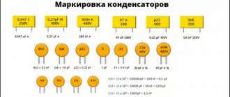
Capacitor markings
The marking of a capacitor, regardless of its type, contains two mandatory parameters - capacitance and rated voltage. The most common digital marking indicates the resistance value. It uses three or four digits.
Briefly, the essence of the three-digit marking: the first two digits on the left indicate the capacitance value in picofarads. The rightmost number shows how many zeros should be added to the numbers on the left. The result is obtained in picofarads. Example: 154 = 15x104 pF. On foreign-made capacitors, pF are designated as mmf.
In a four-digit code, the capacitance in picofarads is indicated by the first three digits, and the fourth indicates the number of zeros to be added. For example: 2353=235x103 pF.
To designate the capacity, alphanumeric markings containing the letter R can also be used, which indicates the location of the decimal point. For example, 0R8=0.8 pF.
On the case, the voltage value is indicated by a number followed by the letters: V, WV (which means “operating voltage”). If there is no indication of the permissible voltage, then the capacitor can only be used in low-voltage circuits.
In addition to capacitance and voltage, other characteristics of the part may be indicated on the case:
Basic parameters of capacitors
Capacity
This indicator characterizes the capacitor's ability to accumulate electrical charge. The larger the area of the conductor plates and the smaller the thickness of the dielectric layer, the larger the capacitance. This characteristic also depends on the dielectric material. The device indicates the nominal capacity. The actual capacity, depending on operating conditions, may differ from the nominal capacity within significant limits. Standard options for nominal capacity range from units of picofarads to several thousand microfarads. Some models may have a capacity of several tens of farads.
Classic capacitors have a positive capacitance, that is, the greater the applied voltage, the greater the accumulated charge. But today, devices with unique properties, which scientists call “anti-capacitors,” are under development. They have negative capacitance, that is, as the voltage increases, their charge decreases, and vice versa. The introduction of such anti-capacitors into the electronics industry will speed up the operation of computers and reduce the risk of overheating.
What happens if you install a drive with a larger/smaller capacity than required? If we are talking about smoothing out voltage ripples in power supplies, then installing a capacitor with a capacitance exceeding the required value (within reasonable limits - up to 90% of the nominal value) in most cases improves the situation. Installing a capacitor with a smaller capacitance may degrade the performance of the circuit. In other cases, the possibility of installing a part with parameters different from the specified ones is determined specifically for each case.
Specific capacitance
The ratio of the nominal capacitance to the volume (or mass) of the dielectric. The thinner the dielectric layer, the higher the specific capacitance, but the lower its breakdown voltage.
Energy Density
This concept refers to electrolytic capacitors. The maximum density is typical for large capacitors, in which the mass of the housing is significantly lower than the mass of the plates and electrolyte.
Rated voltage
Its value is reflected on the housing and characterizes the voltage at which the capacitor operates during its service life with parameters fluctuating within specified limits. The operating voltage must not exceed the rated value. For many capacitors, the rated voltage decreases as the temperature increases.
Polarity
Polar capacitors are electrolytic capacitors that have positive and negative charges. On domestically produced devices, a “+” sign was usually placed at the positive electrode. On imported devices, a negative electrode is indicated, next to which there is a “-” sign. Such capacitors can perform their functions only if the voltage polarity is connected correctly. This fact is explained by the chemical features of the reaction of the electrolyte with the dielectric.
Most charge storage devices belong to the group of non-polar capacitors. These parts ensure correct operation no matter how the pins are connected to the circuit.
About real capacitor
A real capacitor has two resistances at the same time: active and capacitive.
They should be considered connected in series.
The voltage applied by the generator to the active resistance and the current flowing through the active resistance are in phase.
The voltage applied by the generator to the capacitive reactance and the current flowing through the capacitive reactance are shifted in phase by 90 0. The resulting voltage applied by the generator to the capacitor can be determined using the parallelogram rule.
At active resistance, the voltage U act and current I are in phase. At capacitive reactance, the voltage Uc lags behind the current I by 90 0. The resulting voltage applied by the generator to the capacitor is determined by the parallelogram rule. This resulting voltage lags behind the current I by some angle φ, always less than 90 0.
Capacitor design
The designs of modern capacitors are varied, but several typical options can be distinguished:
Batch design
Used in glass-enamel, ceramic and glass-ceramic capacitors. The packages are formed by alternating layers of plates and dielectric. The covers can be made of foil, or they can be layers on dielectric plates - sprayed or applied by burning.
Each stack capacitor has upper and lower plates that have contacts at the ends of the stack. Terminals are made of wire or tape strips. The package is pressed, sealed, and covered with protective enamel.
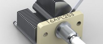
Tubular design
High-frequency capacitors can have this design. They are a ceramic tube with a wall thickness of 0.25 mm. A silver conductive layer is applied to its outer and inner sides by burning in. The outside of the part is treated with an insulating substance. The inner lining is brought out onto the outer layer to attach a flexible lead to it.
Disc design
This design, like the tubular one, is used in the manufacture of high-frequency capacitors.
The dielectric in disk capacitors is a ceramic disk. Silver plates are burned onto it, to which flexible leads are connected.
Cast sectional construction
It is used in monolithic multilayer ceramic capacitors used in modern equipment, including integrated circuits. A part with 2 grooves is made by casting ceramics. The grooves are filled with silver paste, which is secured using the implantation method. Flexible leads are soldered to the silver inserts.
Roll design
Characteristic of paper film low-frequency capacitors with high capacity. Paper tape and metal foil are rolled into a roll. In metal-paper capacitors, a metal layer up to 1 micron thick is applied to the paper tape.
Parasitic parameters of capacitors
Capacitors, in addition to their main characteristics, have so-called “parasitic parameters” that distort the operating properties of the oscillating circuit. They must be taken into account when designing the circuit.
These parameters include their own resistance and inductance, which are divided into the following components:
Parasitic parameters also include Vloss - an insignificant value expressed as a percentage, which shows how much the voltage drops immediately after the capacitor stops charging.
What is a modern multimeter like?
A modern multimeter is digital. Allows you to measure many different things. But for a high-quality continuity test of the capacitor, you need a device that can measure capacitance.
An old-school radio amateur will say that you can do without such a mode by measuring resistance. But this is not entirely true, and for some capacitors it is not even true at all.
Therefore, we are looking for a device whose switch can be set to one of the values, including the Latin letter F. This letter comes from the name of the unit of measurement of electrical capacitance - farad. The unit is named after the famous English physicist Michael Faraday, and not the actor Semyon Farada. We owe many of the electrical engineering terms familiar to us to Faraday. And the unit of measurement of capacity.
About the charge of a capacitor.
Let's close the circuit. A capacitor charging current will flow through the circuit. This means that some electrons from the left plate of the capacitor will go into the wire, and the same number of electrons will go from the wire to the right plate. Both plates will be charged with opposite charges of the same magnitude.
There will be an electric field between the plates in the dielectric.
Now let's open the circuit. The capacitor will remain charged. Let's short-circuit its lining with a piece of wire. The capacitor will instantly discharge. This means that an excess of electrons will go from the right plate into the wire, and a lack of electrons will go from the wire to the left plate. There will be equal amounts of electrons on both plates, and the capacitor will discharge.
To what voltage does the capacitor charge?
It is charged to the voltage that is applied to it from the power source.
How to check the performance of a capacitor
To check the capacitor for functionality, use a multimeter. Before checking the drive, it is necessary to determine which device is located in the circuit - polar (electrolytic) or non-polar.
Checking the polar capacitor
When checking a polar capacitor, it is necessary to observe the correct polarity of connecting the probes: the positive one must be pressed against the positive leg, the negative one against the minus leg. If you reverse the polarity, the capacitor will fail.
After desoldering the parts, it is placed in free space. The multimeter is switched on to the resistance measurement mode (“diagnosis”).
Use probes to touch the terminals of the device, observing polarity. The correct situation is when the first value appears on the display and begins to gradually increase. The maximum value that must be achieved for a working device is 1. If you just touched the leads with the probes and the number 1 immediately appears on the screen, it means the device is faulty. The appearance of “0” on the screen means that a short circuit has occurred inside the part.
Checking a non-polar capacitor
In this case, the check is extremely simple. The measurement range is set to 2 MOhm. The probes are connected to the capacitor terminals in any order. The resulting value must exceed two. If the display shows a value less than 2 MOhm, then the part is faulty.