The author of the article is a professional tutor, author of textbooks for preparing for the Unified State Exam Igor Vyacheslavovich Yakovlev
Topics of the Unified State Examination codifier: electrical capacitance, capacitor, energy of the electric field of a capacitor.
The previous two articles were devoted to a separate consideration of how conductors behave in an electric field and how dielectrics behave. Now we need to combine this knowledge. The fact is that the joint use of conductors and dielectrics in special devices - capacitors - is of great practical importance.
But first, let’s introduce the concept of electrical capacitance.
Capacitance of a solitary conductor
Let us assume that the charged conductor is located so far from all other bodies that the interaction of the charges of the conductor with surrounding bodies can be ignored. In this case, the conductor is called solitary.
The potential of all points of our conductor, as we know, has the same value, which is called the potential of the conductor. It turns out that the potential of a solitary conductor is directly proportional to its charge. The proportionality coefficient is usually denoted by , so
The quantity is called the electrical capacitance of the conductor and is equal to the ratio of the charge of the conductor to its potential:
(1)
For example, the potential of a solitary sphere in a vacuum is equal to:
where is the charge of the ball and is its radius. Hence the capacity of the ball:
(2)
If the ball is surrounded by a dielectric medium with dielectric constant , then its potential decreases by a factor of:
Accordingly, the capacity of the ball increases by several times:
(3)
The increase in capacitance in the presence of a dielectric is the most important fact. We will meet him again when considering capacitors.
From formulas (2) and (3) we see that the capacity of the ball depends only on its radius and the dielectric constant of the environment. The same will happen in the general case: the capacitance of an isolated conductor does not depend on its charge; it is determined only by the size and shape of the conductor, as well as the dielectric constant of the medium surrounding the conductor. Capacitance also does not depend on the conductor substance.
What is the meaning of the concept of capacity? The capacitance shows how much charge needs to be imparted to the conductor in order to increase its potential by V. The greater the capacitance, the correspondingly more charge must be placed on the conductor for this.
The unit of measurement for capacitance is farad (F). From the definition of capacity (1) it is clear that Ф = C/V.
For fun, let's calculate the capacity of the globe (it is a conductor!). We consider the radius to be approximately equal to km.
µF.
As you can see, F is a very large capacity.
The unit of measurement of capacitance is also useful because it allows you to greatly save on the designation of the dimension of the dielectric constant. In fact, let us express from formula (2):
Therefore, the dielectric constant can be measured in F/m:
F.
It's easier to remember that way, isn't it?
Formulas for measuring capacitor voltage
The numerical indicator of voltage is equal to electromotive force. It is also defined as the capacity divided by the amount of charge, based on the formula for determining its value. According to another rule, the voltage is equal to the leakage current divided by the insulation resistance.
You might be interested in How to choose a color temperature
Basic formulas for calculation
In general, a capacitor is a device for accumulating electrical charge, consisting of several plate electrodes that are separated by dielectrics. The device has an electrode measured in farads. One farad is equal to one coulomb. The voltage of the device is affected by the current, the indicators of which can be calculated using the formulas described above.
Capacitance of a parallel plate capacitor
The capacitance of a solitary conductor is rarely used in practice. In normal situations, guides are not solitary. A charged conductor interacts with surrounding bodies and induces charges on them, and the potential of the field of these induced charges (according to the principle of superposition!) changes the potential of the conductor itself. In this case, it can no longer be argued that the potential of the conductor will be directly proportional to its charge, and the concept of the capacitance of the conductor itself actually loses its meaning.
It is possible, however, to create a system of charged conductors, which, even if a significant charge accumulates on them, almost does not interact with surrounding bodies. Then we can talk about capacitance again - but this time about the capacitance of this system of conductors.
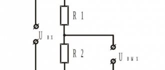
The simplest and most important example of such a system is a parallel-plate capacitor. It consists of two parallel metal plates (called plates) separated by a layer of dielectric. In this case, the distance between the plates is much less than their own dimensions.
First, let's look at an air capacitor with air between the plates.
Let the charges of the plates be equal and . This is exactly what happens in real electrical circuits: the charges of the plates are equal in magnitude and opposite in sign. The quantity - the charge of the positive plate - is called the charge of the capacitor.
Let be the area of each plate. Let's find the field created by the plates in the surrounding space.
Since the dimensions of the plates are large compared to the distance between them, the field of each plate far from its edges can be considered a uniform field of an infinite charged plane:
Here is the field strength of the positive plate, is the field strength of the negative plate, and is the surface charge density on the plate:
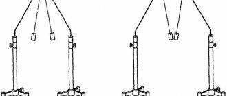
In Fig. 1 (left) shows the field strength vectors of each plate in three areas: to the left of the capacitor, inside the capacitor and to the right of the capacitor.
Rice. 1. Electric field of a parallel-plate capacitor
According to the principle of superposition, for the resulting field we have:
It is easy to see that to the left and right of the capacitor the field vanishes (the fields of the plates cancel each other):
Inside the capacitor the field doubles:
or
(4)
The resulting field of the plates of a flat capacitor is shown in Fig. 1 on the right. So:
A uniform electric field is created inside a flat capacitor, the intensity of which is found according to formula (4). Outside the capacitor, the field is zero, so the capacitor does not interact with surrounding bodies.
Let us not forget, however, that this statement is derived from the assumption that the plates are infinite planes. In fact, their dimensions are finite, and so-called edge effects occur near the edges of the plates: the field differs from the uniform one and penetrates into the outer space of the capacitor. But in most situations (and even more so in Unified State Examination problems in physics), edge effects can be neglected and one can act as if the statement in italics is true without any reservations.
Let the distance between the capacitor plates be equal to . Since the field inside the capacitor is uniform, the potential difference between the plates is equal to the product of (remember the relationship between voltage and intensity in a uniform field!):
(5)
The potential difference between the plates of the capacitor, as we see, is directly proportional to the charge of the capacitor. This statement is similar to the statement “the potential of an isolated conductor is directly proportional to the charge of the conductor,” with which the whole conversation about capacitance began. Continuing this analogy, we define the capacitance of a capacitor as the ratio of the charge of the capacitor to the potential difference between its plates:
(6)
The capacitance of a capacitor shows how much charge needs to be imparted to it in order for the potential difference between its plates to increase by V. Formula (6), therefore, is a modification of formula (1) for the case of a system of two conductors - a capacitor.
From formulas (6) and (5) we easily find the capacity of a flat air capacitor:
(7)
It depends only on the geometric characteristics of the capacitor: the area of the plates and the distance between them. Let us now assume that the space between the plates is filled with a dielectric with dielectric constant . How will the capacitance of the capacitor change?
The field strength inside the capacitor will decrease by a factor, so that instead of formula (4) we now have:
(8)
Accordingly, the voltage across the capacitor:
(9)
Hence the capacitance of a flat capacitor with a dielectric:
(10)
It depends on the geometric characteristics of the capacitor (the area of the plates and the distance between them) and on the dielectric constant of the dielectric filling the capacitor.
An important consequence of formula (10): filling a capacitor with a dielectric increases its capacity.
Examples of solving problems on the topic “Capacitance of a capacitor”
EXAMPLE 1
| Exercise | What is the electrical capacitance of a parallel-plate double-layer capacitor? One of the dielectric layers is porcelain with a thickness of = 2 mm; the second layer is ebonite (mm). The area of the capacitor plates is 0.01 m2. |
| Solution | To solve this problem, the easiest way is to apply the formula for calculating the capacitance of a layered flat capacitor, given that we have only two layers: |
Capacitor
-
this is an element of an electrical circuit that, with a small size, is capable of accumulating electrical charges of a sufficiently large magnitude
. The simplest model of a capacitor is two electrodes, between which there is any dielectric. The role of the dielectric in it is played by paper, air, mica and other insulating materials, the task of which is to prevent the contact of the plates.
Energy of a charged capacitor
A charged capacitor has energy. This can be verified by experience. If you charge a capacitor and short-circuit it to a light bulb, then (provided that the capacitance of the capacitor is large enough) the light bulb will light up for a short time.
Consequently, energy is stored in a charged capacitor, which is released when it is discharged. It is not difficult to understand that this energy is the potential energy of interaction between the plates of the capacitor - after all, the plates, being oppositely charged, attract each other.
We will now calculate this energy, and then we will see that there is a deeper understanding of the origin of the energy of a charged capacitor.
Let's start with a flat-plate air capacitor. Let us answer the following question: what is the force of attraction of its plates to each other? We use the same values: capacitor charge, plate area.
Let us take an area on the second plate so small that the charge of this area can be considered a point charge. This charge is attracted to the first plate with a force
where is the field strength of the first plate:
Hence,
This force is directed parallel to the field lines (i.e., perpendicular to the plates).
The resulting force of attraction of the second plate to the first is the sum of all these forces with which all kinds of small charges of the second plate are attracted to the first plate. With this summation, the constant factor is taken out of the bracket, and everything in the bracket is summed up and gives . As a result we get:
(11)
Let us now assume that the distance between the plates has changed from the initial value to the final value. The force of attraction of the plates does the following work:
The sign is correct: if the plates come closer together, then the force does positive work, since the plates are attracted to each other. On the contrary, if you remove the plates, then the work done by the attractive force turns out to be negative, as it should be.
Taking into account formulas (11) and (7) we have:
Where
This can be rewritten as follows:
Where
(12)
The work of the potential force of attraction of the plates turned out to be equal to the change with a minus sign of the quantity . This precisely means that - the potential energy of interaction of the plates, or the energy of a charged capacitor.
Using the relationship, from formula (12) you can obtain two more formulas for the energy of the capacitor (see this for yourself!):
(13)
(14)
Formulas (12) and (14) are especially useful.
Let us now assume that the capacitor is filled with a dielectric with dielectric constant . The force of attraction of the plates will decrease by a factor, and instead of (11) we get:
When calculating the work of force , as is easy to see, the quantity will enter the container, and formulas (12) - (14) will remain unchanged. The capacitance of the capacitor in them will now be expressed according to formula (10).
So, formulas (12) - (14) are universal: they are valid both for an air capacitor and for a capacitor with a dielectric.
Properties
Capacity
. This is the main property of a capacitor. Measured in Farads and calculated using the following formula (for a parallel-plate capacitor):
where C, q, U are respectively the capacitance, charge, voltage between the plates, S is the area of the plates, d is the distance between them, is the dielectric constant, is the dielectric constant equal to 8.854 * 10^-12 F/m.
Capacitor Polarity
;
Rated voltage
;
Specific capacitance and others
.
The capacitance value of the capacitor depends on
Plate area
. This is clear from the formula: capacity is directly proportional to charge. Naturally, by increasing the area of the plates, we obtain a larger amount of charge.
Distances between plates
. The closer they are located, the greater the intensity of the resulting electric field.
Volta concept
As the scientist’s notes indicate, already in 1778 he received an idea of the difference in potentials, which he called tension. Since 1775, Volta adhered to the concept of electrical capacity - capacita, put forward by his teacher Beccaria. Volta already knows that the electrophorus is capable of accumulating charge, calls the device a capacitor, and decides to confirm the theory with practice. Otherwise, find the relationship between voltage, capacity and volume (quantita) of charge.
Volta started with a Leyden jar. He charged it from a static generator and tried to determine the energy of the capacitor in three ways:
- I observed the resulting electric arc spark from different designs of Leyden jars charged with the same voltage.
- He measured the amount of work produced by electrostatic friction generators until the electrometer readings grew to a certain level.
- I discharged Leyden jars in the open air and tried to compare the electric shock they produced over time.
All of the above led the researcher to the strange conclusion that tall Leyden jars are more spacious (with the same areas of the linings and other equal conditions). This is probably due to the rate of discharge of their arc in air due to differences in the curvature of the surfaces. Volta linked the force of the discharge with electric current: the faster the fluid flows, the hotter (it feels) the effect. As a result, Volta believed that the potential difference alone determines the process of impact occurrence. He decided that voltage could be measured in two ways:
- Through the number of revolutions of the static charge generator.
- Comparing the force of the electric shock when discharging a Leyden jar.
Volta found that by charging an empty Leyden jar with a full one, the shock was twice as weak. Gradually (1782) Volta came to the conclusion that the above quantities are related to each other: tension x capacity ~ load, in the modern world it looks like UC = q or C = q / U.
Volta concluded that capacity is greater where more charge can be accommodated at lower voltage. The conclusion was that the amount of accumulated fluid is directly proportional to the area of the flat capacitor plates. Which is consistent with modern formulas. Volta generalized his knowledge to the case of an arbitrary conductor (experimented with the rods of Leyden jars). By changing the distance between the plates, I set:
C ~ S/d.
Which actually became an expression of the capacitance of a parallel-plate capacitor. Volta explained the dependence by the presence of a certain resistance between the plates, meaning air. By changing the distance, it is possible to vary this parameter in both directions. This is slightly inconsistent with modern concepts, but Volta helped Georg Ohm 40 years later deduce the relationship between current and voltage.
In fact, the measurements were made on the basis of the field work, which appeared only due to the charge of the capacitor. Obviously, the indicated quantity is equal to energy, one of the first physical characteristics used to derive analytical expressions.
How is a capacitor charged and discharged?
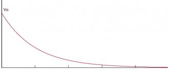
When connected to a direct current source, the plates of the capacitor are charged, one acquires a positive potential, and the other a negative one. Between the plates, electric charges of opposite sign, but equal in value, create an electric field. When the voltages become the same on both the plates and the source of the supplied current, the movement of electrons will stop and charging of the capacitor will end. For a certain period of time, the capacitor retains charges and functions as an autonomous source of electricity. It can remain in this state for quite a long time. If instead of a source, you include a resistor in the circuit, the capacitor will discharge onto it.
Processes occurring in a capacitor
When the device is connected to alternating or direct current, different processes will occur in it. Direct current will not flow through the circuit with a capacitor. Since there is a dielectric between its plates, the circuit is actually open.
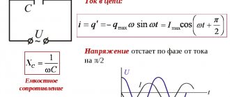
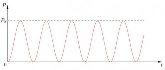
Alternating current, due to the fact that it periodically changes direction, can pass through a capacitor. In this case, a periodic discharge and charge of the capacitor occurs. During the first quarter of the period, the charge reaches its maximum, electrical energy is stored in it, in the next quarter the capacitor is discharged and the electrical energy is returned back to the network. In an alternating current circuit, a capacitor has, in addition to active resistance, also a reactive component. In addition, in a capacitor, the current leads the voltage by 90 degrees, this is important to take into account when constructing vector diagrams.
Volumetric electrical energy density
strength of a flat capacitor is equal to E = U d, its capacitance is C = ε 0 ε S d.
It follows that W e = C · U 2 2 = ε 0 · ε · S · E 2 · d 2 2 d = ε 0 · ε · E 2 2 V, where V = S d denotes the volume of space between the plates with the presence electric field. This relationship leads to the formula for the following physical quantity.
The physical quantity W e = ε 0 · ε · E 2 2 is the electrical energy per unit volume of space in which the electric field is created. It is called the volumetric density of a given electrical energy .
The capacitor field energy created by any distribution of electric charges in space is found by integrating W e over the entire volume in which the electric field was created.
Calculation of capacitor parameters online
I don’t know about you, but I never liked working and calculating capacitances of capacitors. What was most annoying was the presence in the source data of capacitances in different denominations, in picofarads, nanofarads, microfarads. They had to be converted to Farads, which entailed the most stupid errors in calculations. A capacitor is, in principle, any structure that can store stored electrical potential. If this design not only stores electricity, but also generates it, then this is already a power source and not a capacitor.
The design of capacitors can be any, but most often in practice a flat capacitor is used, consisting of two conducting plates, between which there is some kind of dielectric. This is due to the fact that the calculation of the capacitance of such a capacitor is carried out according to a well-known formula and the simplicity of its creation. By rolling such a flat capacitor into a roll, we get that despite the actual modest size of the “roll”, there is a flat capacitor tens of centimeters long and with increased capacity.
The capacitances of some forms of capacitors are known, and we will consider them further.
But I would like to note that, in our opinion, the development potential of capacitors has not been fully completed. After all, the design of any capacitor can have any shape, the materials from which the plates are made or the dielectric layer can also be anything within the limits of the periodic table. The only difficulty is the impossibility of theoretically calculating the potential capacity of a newly created (different design) capacitor. This makes it difficult to find the best capacitor design.
There is a good book on looking at the electrical capacitance of various shapes. For the curious, I recommend searching the Internet: Calculation of electrical capacitance by Yu.Ya. Yosell, 1981
This bot calculates the parameters of typical capacitor shapes. The difference from other calculators present on the Internet is the ability to set parameters that you know in order to calculate the rest.
And the last innovation that you can use. You don't necessarily have to convert given data to meters, farads, etc. It is enough to indicate the dimension of the data.
For example, if the capacitance is known and equal to 100 picofarads, then the bot can write c = 100 picofarads or c = 100 pF, and the bot itself will convert to Farads.
The result will also be presented optimally for the user’s visual perception.
This became possible with the creation of a bot System of units of measurement online