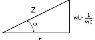
General information
The word "condenser" is translated from Latin as "thickening". Therefore, a device that allows one to obtain a uniform electric field was called this term. In physics there is a clear definition of such a device. According to him, a capacitor is a system of two flat conductors the distance between which is much less than their dimensions. The first such device was the Leyden Jar.
In 1745, the Dutchman Pietervan Muschenbroek and his student Kuneus in the city of Leiden assembled a jar-shaped device designed for storing and accumulating charges. The device contained the following components:
- glass cylinder;
- outer and inner shells;
- wooden cork;
- wire conductor.
The shells covered approximately two-thirds of the vessel and were made of sheet tin. A metal rod passed through the stopper to ensure the seal of the jar. By touching the submariner with a charged body, the scientist transferred the charges into the container. Upon contact, electrons moved to the conductor and accumulated on the electrode. As a result, one plate of the capacitor was charged positively, and the other - negatively.
As it turned out, this design was capable of accumulating a supply of electricity. The invention of the first capacitor led to a deeper understanding of the nature of electricity. With its help, it became possible to understand the behavior of dielectrics and conductors and understand the mechanism of charge separation.
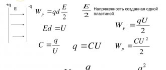
From a physical point of view, the following processes take place in the device. Two separated plates are charged by particles with different signs. The voltage vector of a positively charged conductor is directed away from it in all directions. In this case, the lines of force that are created between the plates do not depend on the distance, they are identical in magnitude and direction. Therefore, the same field is created on the outside of the negative plate, but with lines entering it.
Since the charges on the electrodes are the same, the field strength inside the plates is equal to E = E1 * E2 = 2E1 = 2E2. Outside, the lines of force are directed towards each other, so the total value of energy behind the plates is zero.
Thus, the capacitor not only allows you to create a uniform field inside it, but also to block it from the outside. Consequently, such a device can accumulate a fairly high charge value.
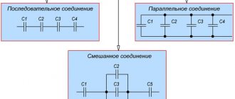
Electrical capacity
The ability of a device to accumulate charge primarily depends on its capacity. Its value can be found by dividing the charge concentrated on the plates by the potential difference between them: C = q / U. The result obtained is measured in farads [F]. So, a capacitance of 1 farad will be equal to the value of a charge of 1 coulomb that creates a voltage at the terminals of the capacitor of 1 volt. A pendant is a fairly large quantity. Therefore, in practice, in various calculations one has to deal with microfarads (µF), nanofarads (nF) and picofarads (pF).
After creating the Leyden Jar, scientists conducted a series of experiments aimed at increasing the amount of energy stored by the device. Thus, it was discovered that if a dielectric is placed between the plates of a capacitor, it not only prevents short-circuiting of the conductors, but also affects the capacitance.
Let there be a device whose plates have an area S. Between the plates there is a non-conductor of current, characterized by a dielectric constant ε. This is a coefficient showing how many times the intensity in a uniform field is less than the value created by the same charges in a vacuum.
It can be assumed that the positive charge will accumulate on the left plate, and the negative charge on the right. To find the capacitance of a capacitor you need to use the following sequence of actions:
- Find the field strength in the middle of the device. To do this, each plate must be imagined as an infinitely uniformly charged plane. Then: E1 = σ / (2 * ε * ε0). Since the fields inside add up, the calculation formula will take the form: E = σ / (ε * ε0).
- Determine the surface charge density. This is a quantity that shows the ratio of the charge to the area over which it is distributed: σ = q / S.
- Express the voltage between the plates in terms of charge. The field between the plates is uniform. This means that the voltage can be found by multiplying the voltage by the distance: U = E * d. Then, using the obtained formulas for E and σ, we can write: U = (q * d) / (ε * ε0 * S).
- Calculate the electrical capacitance by substituting the expressions into the formula: C = q / U. The result is: C = (ε * ε0 * S) / d.
Thus, the larger the area of the plates, the higher the capacitance of the capacitor. It follows that more charge will be accumulated. Moreover, its value also depends on the distance between the plates. If d decreases, then the capacity increases.
Capacitor discharge
After the capacitor is charged, turn off the power source and connect the load R. Since the capacitor is already charged, it itself has turned into a power source. Load R formed a passage between the plates. Negatively charged electrons accumulated on one plate, according to the force of attraction between unlike charges, will move towards positively charged ions on the other plate.
At the moment of connecting R, the voltage on the capacitor is the same as after the end of the transition charging period. The initial current according to Ohm's law will be equal to the voltage on the plates divided by the load resistance.
As soon as current flows in the circuit, the capacitor will begin to discharge. As charge is lost, the voltage will begin to drop. Therefore, the current will also drop. As the voltage and current values decrease, their rate of decline will decrease.
The charging and discharging time of a capacitor depends on two parameters - the capacitance of the capacitor C and the total resistance in the circuit R. The larger the capacitance of the capacitor, the more charge must pass through the circuit, and the more time the charging/discharging process will require (current is defined as the amount of charge, passed along the conductor per unit time). The higher the resistance R, the lower the current. Accordingly, more time will be required for charging.
The product RC (resistance times capacitance) forms a time constant ?
(tau).
For one ?
The capacitor is charged or discharged by 63%.
For five ?
The capacitor is charged or discharged completely.
For clarity, let’s substitute the values: a capacitor with a capacity of 20 microfarads, a resistance of 1 kiloohm and a power source of 10V. The charging process will look like this:
Device energy
It is impossible to charge a capacitor instantly. This process requires some time. This phenomenon is used in radio engineering. So, with the help of a capacitor, pulse bursts are smoothed out. To a first approximation, a capacitor is similar to a battery. But at the same time, it differs from it in the principle of energy storage , capacity and charge-discharge rate. When a power source is connected to the terminals of the device plates, the capacitor accumulates charge on them.~
The operation of the device can be explained by analogy with the flow of water. Let there be a vessel with a liquid with a cross-sectional area S. In fact, this is the equivalent of a container. Then the water will be a charge, and the height of the water column will be a voltage. It turns out that energy is the product of charges and height. But if a battery can be imagined as a vessel in which there is a thin hose (lead) and through which water flows (charge), then in a capacitor its tube diameter will be equal to the size of the entire jar. That is, the device can instantly release all the accumulated charge.
When voltage is applied to the plates, the dielectric becomes electrified. As a result, a displacement occurs and energy is transferred to the plates. On one of them there will be an excess of electrons, and it will be conditionally charged negatively, and on the second there will be a deficiency - the conductor will become positive. Therefore, in the formula that determines the charge on the capacitor plates, the dielectric constant of a non-conducting substance is of great importance.
Force arises between the plates. The magnitude acting from the first side is equal to F = ε1 * q, and from the second side F = ε2 * q. Thus, we can write: F = ε1 * q = ε2 * q = E / 2 * q. When the distance between the plates increases from zero to d, the work will be performed: A = F * d. It is aimed at overcoming the interaction force between charged conductors.
That is: A = E / 2 * q * d. Based on the fact that ε = U/d it will be correct to write: A = 1 / 2 q * U. This means that the mechanical work A in accordance with the law of conservation of energy will be equal to the number of charges stored in the electric field of the capacitor: We = C * U2 / 2.
It should be noted that when an alternating signal is applied inside the dielectric, the charge signs constantly change. As a result, heating occurs, which causes the capacitor to fail. This phenomenon is characterized by the dielectric loss tangent. It is defined as the ratio of expended power to reactive power.
Unit converter
The time constant is determined by the formula
where τ
is the time constant in seconds,
R
is the resistance in ohms, and
C
is the capacitance in farads.
The time constant of an RC circuit is defined as the time it takes for a capacitor to charge to 63.2% of its maximum possible charge, assuming the initial charge is zero. Note that the capacitor will charge up to 63.2% in time τ
and almost completely (up to 99.3%) will charge in time 5
τ
.
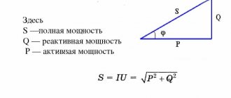
Energy E
, which is stored by a capacitor fully charged to voltage
V
, provided that the charging time
T ≫ τ
is determined by the formula
where C
is the capacitance in farads and
V
is the voltage in volts.
Maximum current I
determined by Ohm's law:
Maximum charge Q
determined by the formula
where C
is the capacitance in farads and
V
is the voltage in volts.
Filtering electrolytic capacitors on a computer motherboard
Application
The ADSL frequency splitter is a low-pass filter and three connectors in a housing
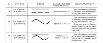
Capacitors are often used in a variety of electrical and electronic devices and systems. You probably won't find any electronic device that doesn't contain at least one capacitor.
Capacitors are used for energy storage, providing energy pulses, for filtering supply voltage, for power factor correction, for DC decoupling, in electronic frequency filters, for filtering noise, for starting electric motors, for storing information, for tuning oscillating circuits, in various sensors, in capacitive screens of mobile phones... The list goes on and on.
Resistance-capacitance (RC) circuits are commonly used as simple low-pass and high-pass filters, as well as simple integrating and differentiating circuits.
RC Low Pass Filters
Example of a two-stage RC low-pass filter with a non-inverting unity gain op-amp used as a buffer between the two filter stages
Low-pass filters pass only low-frequency signals and reject high-frequency signals. The cutoff frequency is determined by the filter components.
Such filters are widely used in electronics. For example, they are used in subwoofers to prevent high-frequency sounds from being fed to them that they cannot reproduce. Low-pass filters are also used in radio transmitters to block unwanted high-frequency components in the transmitted signal.
Those who use an ADSL Internet connection always have frequency dividers installed with low-pass filters that prevent DSL signals from interfering with analog devices (phones) and preventing interference from analog devices from affecting DSL equipment connected to a regular telephone line.
Low-pass filters are used to process signals before analog-to-digital conversion. Such filters improve the quality of analog signals when they are sampled and are necessary to suppress high-frequency components of the signal above the Nyquist frequency so that it satisfies the requirements of Kotelnikov's theorem for a given sampling frequency, that is, the maximum frequency should not be higher than half the sampling frequency.
The top picture shows a simple low pass filter. It uses only passive components, which is why it is called a passive low pass filter (LPF). More complex passive low-pass filters also use inductors.
Unlike passive low-pass filters, active filters use amplification devices such as transistors or operational amplifiers. Passive filters also often have operational amplifiers used for decoupling.
Depending on the number of capacitors and inductors that affect the slope of the filter's frequency response, they are usually called “first-order” filters, “second-order” filters, and so on.
A filter consisting of only one resistor and one capacitor is called a first order filter.
Simple Passive RC High Pass Filter
High-pass filters pass only high-frequency components of signals and attenuate low-frequency components. High-pass filters are used, for example, in audio crossovers to suppress low-frequency components in signals fed to high-frequency speakers (“tweeters”), which cannot reproduce such signals and also have low power compared to the power of low-frequency speakers. signals.
Active High Pass Filter with Op-Amp
High-pass filters are often used to block the DC component of signals where it is undesirable.
For example, professional microphones often use DC phantom power, which is supplied through the microphone cable. At the same time, the microphone records variable signals such as human voice or music.
DC voltage should not appear at the output of the microphone and should not enter the input of the microphone amplifier, so a high-pass filter is used to block it.
A simple bandpass filter assembled from two stages - a low-pass filter (C2, R2) and a high-pass filter (C1, R1)
If a low-pass filter and a high-pass filter are placed next to each other, they form a bandpass filter
, which only allows frequencies within a certain frequency band to pass through and does not allow frequencies outside that band to pass through. Such filters are widely used in radio receivers and radio transmitters.
In receivers, bandpass filters are used only to selectively pass and amplify radio station signals within the required narrow frequency band. At the same time, signals from other radio stations outside this band are suppressed. Transmitters can only transmit radio signals within a certain frequency range that is authorized for them.
Therefore, they use bandpass filters to limit the bandwidth of the transmitted signal so that it fits within acceptable limits.
The time constant is determined by the formula
where τ
is the time constant in seconds,
R
is the resistance in ohms, and
C
is the capacitance in farads.
The time constant of an RC circuit is defined as the time it takes for a capacitor to charge to 63.2% of its maximum possible charge, assuming the initial charge is zero. Note that the capacitor will charge up to 63.2% in time τ
and almost completely (up to 99.3%) will charge in time 5
τ
.
Energy E
, which is stored by a capacitor fully charged to voltage
V
, provided that the charging time
T ≫ τ
is determined by the formula
where C
is the capacitance in farads and
V
is the voltage in volts.
Maximum current I
determined by Ohm's law:
Maximum charge Q
determined by the formula
where C
is the capacitance in farads and
V
is the voltage in volts.
Filtering electrolytic capacitors on a computer motherboard
One of the important elements of the electrical circuit is a capacitor, the formulas for which allow you to calculate and select the most suitable option. The main function of this device is to accumulate a certain amount of electricity. The simplest system includes two electrodes or plates separated by a dielectric. What is the capacitance of a capacitor measured in?One of the most important characteristics of a capacitor is its capacity. This parameter is determined by the amount of electricity accumulated by this device. The accumulation occurs in the form of electrons. The number of them placed in the capacitor determines the capacitance value of a particular device. The unit used to measure capacitance is the farad. A capacitor's capacity of 1 farad corresponds to an electric charge of 1 coulomb, and the potential difference across the plates is 1 volt. This classical formulation is not suitable for practical calculations, since the capacitor collects not charges, but electrons. The capacity of any capacitor is directly dependent on the volume of electrons that can accumulate during normal operating conditions. The farad is still used to denote capacitance, and the quantitative parameters are determined by the formula: C = Q / U, where C means capacitance, Q is charge in coulombs, and U is voltage. Thus, the mutual relationship between charge and voltage is visible, influencing the capacitor’s ability to accumulate and retain a certain amount of electricity. To calculate the capacitance of a parallel plate capacitor, the formula is used: in which ε0 = 8.854187817 x 10⁻¹² f/m is a constant value. Other quantities: ε is the dielectric constant of the dielectric located between the plates, S is the area of the plate, and d is the gap between the plates. Capacitor Energy FormulaClosely related to capacitance is another quantity known as the energy of a charged capacitor. After charging any capacitor, a certain amount of energy is formed in it, which is subsequently released during the discharge process. The capacitor plates interact with this potential energy. They form opposite charges that attract each other. During the charging process, energy from an external source is consumed to separate charges with positive and negative values, which are then located on the plates of the capacitor. Therefore, in accordance with the law of conservation of energy, it does not disappear without a trace, but remains inside the capacitor in the form of an electric field concentrated between the plates. Opposite charges form interaction and subsequent attraction of the plates among themselves. Each capacitor plate under the action of a charge creates an electric field strength equal to E/2. The total field will be the sum of both fields arising in each plate with identical charges having opposite values. Thus, the energy of the capacitor is expressed by the formula: W=q(E/2)d. In turn, stress is expressed using the concepts of tension and distance and is represented as the formula U=Ed. This value, substituted into the first formula, displays the energy of the capacitor in the following form: W = qU/2. To obtain the final result, it is necessary to use the definition of capacitance: C=q/U, and in the end the energy of a charged capacitor will look like this: Wel = CU2/2. Capacitor charge formulaTo perform charging, the capacitor must be connected to a DC circuit. A generator can be used for this purpose. Every generator has internal resistance. When the circuit is closed, the capacitor is charged. A voltage appears between its plates equal to the electromotive force of the generator: Uc = E. The plate connected to the positive pole of the generator is charged positively (+q), and the other plate receives an equal charge with a negative value (-q). The amount of charge q is directly proportional to the capacitance of the capacitor C and the voltage on the plates Uc. This dependence is expressed by the formula: q = C x Uc. During the charging process, one of the capacitor plates gains and the other loses a certain number of electrons. They are transferred through an external circuit under the influence of the electromotive force of the generator. This movement is an electric current, also known as charging capacitive current (Icharge).
Further, the capacitor voltage value will be constant. During charging, a charging current flows through the circuit. At the very beginning, it reaches its maximum value, since the capacitor voltage has a zero value. According to Ohm's law, Izar = E/Ri, since the entire emf of the generator is applied to the resistance Ri. Capacitor Leakage Current FormulaThe leakage current of a capacitor can be compared to the effect of a resistor with some resistance R connected to it. The leakage current is closely related to the type of capacitor and the quality of the dielectric used. In addition, the design of the housing and the degree of its contamination become an important factor. Some capacitors have a leaky housing, which leads to the penetration of moisture from the air and an increase in leakage current. This primarily applies to devices where oiled paper is used as a dielectric. Significant leakage currents arise due to a decrease in the electrical insulation resistance. As a result, the main function of the capacitor is disrupted - the ability to receive and maintain a charge of electric current. The basic formula for the calculation is as follows: Iut = U/Rd, where Iut is the leakage current, U is the voltage applied to the capacitor, and Rd is the insulation resistance. |