The power of technical equipment or power plants (devices, units) supplied by them to perform work is indicated in their technical characteristics. But this does not mean that all of it is used for its intended purpose to achieve results. Only useful power is used to perform work.
General definition of power
Definition and formula of useful power
It is worth considering the concept of useful power and the formula using the example of an electrical circuit. The power that the power source (PS), in particular current, develops in a closed circuit will be the total power.
Circuit diagram
The circuit includes: a current source with EMF (E), an external circuit with a load R and an internal circuit of a power supply whose resistance is R0. The formula for total (total) power is:
Ptotal = E*I.
Here I is the value of the current passing through the circuit (A), and E is the value of the emf (B).
Attention! The voltage drop in each section will be equal to U and U0, respectively.
So the formula will take the form:
Ptotal = E*I = (U + U0) *I = U*I + U0*I.
It can be seen that the value of the product U*I is equal to the power supplied by the source to the load and corresponds to the useful power Ppol.
The value equal to the product U0*I corresponds to the power that is lost inside the power supply for heating and overcoming the internal resistance R0. This is the power loss P0.
The values substituted into the formula show that the sum of useful and lost power makes up the total power of the IP:
Ptotal=Pfloor+P0.
Important! When operating any apparatus (mechanical or electrical), the useful power will be that which remains to perform the required work after overcoming the factors causing losses (heating, friction, counteracting forces).
Provide power reserve
You should not choose a UPS with a rating exactly equal to the power of the connected equipment. To the calculated energy consumption of the load, you need to add another 30%, which will make up the power reserve. This reserve, firstly, will allow you to reload the UPS during operation, and secondly, it will reduce the number of switches to batteries in case of non-critical deviations in the mains voltage.
Important!
For many UPSs (we are talking, first of all, about on-line models), the limits of the voltage regulated without batteries depend on the size of the actual load - the smaller it is relative to the device rating, the wider they are. The power reserve ensures that the UPS rating exceeds the power of the supplied consumers and, accordingly, increases the range of permissible input voltage.
Important!
Purchasing a UPS with a reserve that far exceeds the maximum power consumption of the load (more than the recommended 30%) is not a way to increase the reliability or battery life of an uninterruptible power supply system, but a way to guarantee spending money on a more expensive device, part of the power of which will be unused.
Power supply parameters
Electric current power
In practice, you often have to think about what the power of the current source should be, how many watts (W) or kilowatts (kW) are needed to ensure uninterrupted operation of the device. To understand the essence, you need to have an understanding of such concepts used in physics as:
- total circuit energy;
- EMF and voltage;
- internal resistance of the power supply;
- losses within the individual entrepreneur;
- useful power.
Regardless of what kind of energy the source produces (mechanical, electrical, thermal), its power should be selected with a small margin (5-10%).
Total circuit energy
When a load is connected to the circuit, which will consume energy from a current source (IT), the current will do work. The energy released by all consumers and circuit elements included in the circuit (wires, electronic components, etc.) is called total energy. The energy source can be any: generator, battery, thermal boiler. The total energy value will be the sum of the energy spent by the source on losses and the amount spent on performing specific work.
EMF and voltage
What is the difference between these two concepts?
EMF is electromotive force, it is the voltage that external forces (chemical reaction, electromagnetic induction) create inside a current source (IT). EMF is the force of movement of electrical charges in IT.
EMF definition
For your information. It seems possible to measure the value of E (EMF) only in idle mode (idle). Connecting any load causes a loss of voltage inside the power supply.
Voltage (U) is a physical quantity representing the potential difference ϕ1 and ϕ2 at the output of the voltage source (VS).
Potential difference
Net power
The definition of the concept of total power is used not only in relation to electrical circuits. It is also applicable to electric motors, transformers and other devices capable of consuming both active and reactive components of energy.
Losses inside the power supply
Similar losses occur at the internal resistance of a two-terminal network. For a battery, this is the electrolyte resistance; for a generator, this is the winding resistance, the lead wires of which come out of the housing.
Internal power supply resistance
You won’t be able to simply measure R0 with a tester; you definitely need to know it to calculate P0 losses. Therefore, indirect methods are used.
An indirect method for determining R0 is as follows:
- in x.x mode measure E (B);
- when the load Rн (Ohm) is turned on, Uout (V) and current I (A) are measured;
- The voltage drop inside the source is calculated using the formula:
U0=E-Uout.
At the last stage, R0=U0/I is found.
Circuit for measuring R0
Operating principle of the power supply
Very often on hardware forums you can find sad stories about how someone’s power supply burned out and took with them their mother, processor, video card, screw and Murzik’s cat. Why do power supplies burn? And why does the load, aka the filling of the system unit, ? To answer these questions, let's briefly consider the operating principle of a switching power supply . Computer power supplies use a closed-loop double conversion method. The conversion occurs due to the transformation of current with a frequency not of 50 Hz, as in a household network, but with frequencies above 20 kHz, which allows the use of compact high-frequency transformers with the same output power. Therefore, a computer power supply is much smaller than classic transformer circuits, which consist of a rather impressively sized step-down transformer, a rectifier and a ripple filter. If a computer power supply were made according to this principle, then with the required output power it would be the size of a system unit and would weigh 3–4 times more (just remember a television transformer with a power of 200–300 W). A pulse power supply has a higher efficiency due to the fact that it operates in a switching mode, and the regulation and stabilization of the output voltages occurs using the pulse width modulation method. Without going into details, the principle of operation is that regulation occurs by changing the pulse width, that is, its duration. In short, the operating principle of a pulse power supply is simple: in order to use high-frequency transformers, we need to convert current from the network (220 volts, 50 Hz) into high-frequency current (about 60 kHz). The current from the electrical network goes to the input filter, which cuts off pulsed high-frequency interference generated at work. Next - to the rectifier, at the output of which there is an electrolytic capacitor to smooth out ripples. Next, the rectified DC voltage of about 300 volts is supplied to a voltage converter, which converts the input DC voltage into an AC voltage with a rectangular high-frequency pulse shape. The converter includes a pulse transformer, which provides galvanic isolation from the network and reduces the voltage to the required values. These transformers are made very small compared to classic ones, they have a small number of turns, and a ferrite core is used instead of an iron core. Then the voltage removed from the transformer goes to a secondary rectifier and a high-frequency filter consisting of electrolytic capacitors and inductors. To ensure stable voltage and operation, modules are used that provide smooth switching and overload protection. So, as you may have noticed from the above, a very high voltage current flows in the computer power supply circuit - ~300 volts. Now let's imagine what will happen if any key element of the circuit fails and the protection does not work. High voltage current will briefly flow into the load (until the power supply burns out), and part of the contents of the system unit will most likely not survive this.
Relationship between useful power and efficiency
Efficiency factor (efficiency) is a dimensionless quantity, expressed numerically as a percentage. Efficiency is denoted by the letter η.
kVA to kW - how to correctly convert power
The formula looks like:
η = A/Q,
Where:
- A – useful work (energy);
- Q – energy expended.
As the efficiency increases in various engines, it is permissible to build the following line:
- electric motor – up to 98%;
- ICE – up to 40%;
- steam turbine – up to 30%.
In terms of power, efficiency is equal to the ratio of useful power to the total power delivered by the source. In any case, η ≤ 1.
Important! Efficiency and Ppol are not the same thing. In different work processes, they achieve the maximum of one or the other.
Obtaining maximum energy at the output of the IP
For your information. To increase the efficiency of cranes, injection pumps or aircraft engines, it is necessary to reduce the friction forces of mechanisms or air resistance. This is achieved by using a variety of lubricants, installing higher-class bearings (replacing sliding with rolling), changing the wing geometry, etc.
The maximum energy or power at the output of the IP can be achieved by matching the load resistance Rн and the internal resistance R0 of the IP. This means that Rн = R0. In this case, the efficiency is 50%. This is quite acceptable for low-current circuits and radio devices.
However, this option is not suitable for electrical installations. To avoid wasting large amounts of power, the operating mode of generators, rectifiers, transformers and electric motors is such that the efficiency is approaches 95% and above.
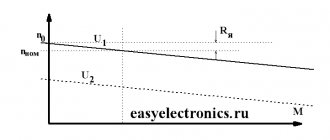
Graph of dependence of Рpol and η on current in the circuit
Achieving maximum efficiency
The formula for the efficiency of a current source is:
η = Pн/Ptotal = R/Rн+r,
Where:
- Pn – load power;
- Ptotal – total power;
- R is the total resistance of the circuit;
- Rн – load resistance;
- r – internal resistance of IT.
As can be seen from the graph shown in Fig. higher, the power Pn tends to zero as the current in the circuit decreases. The efficiency, in turn, will reach its maximum value when the circuit is open and the current is zero; if there is a short circuit in the circuit, it will become zero.
If we look at an elementary heat engine consisting of a piston and a cylinder, then its compression ratio is equal to the expansion ratio. Increasing the efficiency of such a motor is possible if:
- initially high parameters: pressure and temperature of the working fluid before expansion begins;
- bringing their values closer to environmental parameters at the end of expansion.
Achieving ηmax is possible only with the most effective change in the pressure of the working component in the rotational movement of the shaft.
For your information. The thermal efficiency increases with increasing proportion of heat supplied to the working fluid, which is converted into work. The supplied heat is divided into two types of energy: internal in the form of temperature and pressure energy.
Mechanical work, in fact, is performed only by the second type of energy. This gives rise to a number of disadvantages that slow down the process of increasing efficiency:
- some of the pressure goes to the external environment;
- achieving maximum efficiency is impossible without increasing the percentage of pressure energy used for conversion into work;
- it is impossible to increase the efficiency of heat engines without changing S the surface of pressure application, and without removing this surface from the point of rotation;
- the use of only a gaseous working fluid does not contribute to increasing η of heat engines.
To achieve a high efficiency of a heat engine, you need to make a number of decisions. The following device models contribute to this:
- introduce another working fluid with different physical properties into the expansion cycle;
- make the most of both types of energy of the working fluid before expansion;
- generate additional working fluid directly during gaseous expansion.
Information. All modifications to internal combustion engines in the form of: a turbocharger, the organization of multiple or distributed injection, as well as increasing air humidity, bringing the fuel to a state of steam during injection, did not produce tangible results in a sharp increase in efficiency.
Internal combustion engine efficiency
3. Determine the appropriate UPS model by power
It is necessary to compare the power characteristics of the “uninterruptible power supply” offered by the manufacturer or supplier with the indicator obtained by adding a reserve of 30% to the maximum energy consumption of the load (hereinafter referred to as the load indicator). The power value closest to this indicator (rounded up) will be the appropriate UPS rating.
Important!
Rounding down the load indicator is not recommended, since it leads at a minimum to a decrease in the previously established power reserve, and at a maximum to the purchase of an uninterruptible power supply with an insufficient rating.
Important!
Don't forget about the difference between units of measurement and present the load indicator in both watts and volt-amperes. Make sure that the UPS exceeds its rating in terms of both active and apparent power!
Load efficiency
How to calculate power consumption
Whatever the power of the source, the efficiency of electrical appliances will never be 100%.
Exception. The heat pump principle used in the operation of refrigerators and air conditioners brings their efficiency closer to 100%. There, heating one radiator leads to cooling of the other.
Otherwise, energy is spent on extraneous effects. To reduce this expense, you need to pay attention to the following factors:
- when arranging lighting - on the design of lamps, the design of reflectors and the color of the premises (reflective or light-absorbing);
- when organizing heating - for thermal insulation of heat pipes, installation of heat recovery exhaust devices, insulation of walls, ceilings and floors, installation of high-quality double-glazed windows;
- when organizing electrical wiring, select the correct brand and cross-section of conductors according to the future connected load;
- when installing electric motors, transformers and other AC consumers - by the cosϕ value.
Reducing the cost of losses clearly leads to an increase in efficiency when the energy source performs work on the load.
Reducing the influence of factors causing power loss increases the percentage of useful power required to perform work. This is possible by identifying the causes of losses and eliminating them.
Examples of selecting UPS by power
Important!
All power and cosφ values given in the following examples are conditional. When calculating the power of the UPS, use only the parameters from the technical documentation of your equipment!
Selection of UPS for a gas boiler
Let's start with a simple case - choosing a UPS for a single consumer, for example, a gas boiler.
Typically, the documentation of heating devices lists several capacities at once. Assume the following formulations and meanings:
- Max. useful thermal power – 31 kW;
- min. useful thermal power – 10.4 kW;
- electrical power – 165 W.
From the name of the parameters it is clear that the first two characterize the main operation of the boiler, and the third indicates the watts consumed from the electrical network, the amount of which is the actual load on the uninterruptible power supply.
Now let's calculate the required power reserve: 165 x 0.3 = 49.5 W.
Then we determine the load indicator: 165 + 49.5 = 214.5 W.
Using formula 1 and taking cosφ = 0.95, we convert watts into volt-amperes: 214.5 W / 0.95 = 225.7 VA.
As a result, the load indicator will be 214.5 W and 225.7 VA.
Let's look at the power range of the on-line UPS "Stil" - the closest models with a rating of 225 W/250 VA are: SW250, SW250LD, SW250SL and ST250.
Selection of UPS for heating boiler and circulation pump
Let's complicate the problem and assume that a boiler with the same characteristics operates in conjunction with an external circulation pump, the rated power of which is 45 W.
In this case, the load on the UPS in normal mode will be: 165 W + 45 W = 210 W.
However, we do not forget about the starting currents characteristic of the pump and, having tripled its rating, we find the maximum possible starting energy consumption: 165 W + 135 W = 300 W.
Based on its value, we determine the load indicator in W: 300 W + 300 W x 0.3 = 390 W.
Due to the difference in the cosφ value of the boiler and pump (0.95 and 0.7), obtaining the load indicator in VA will require two actions: 165 / 0.95 + 135 / 0.7 = 366.5 VA - total maximum apparent power . 366.5 VA + 366.5 VA x 0.3 = 476.5 VA – load indicator.
Analyzing Shtil products, we come to the conclusion that an on-line UPS of the SW series with an output power of 400 W/500 VA (models SW500L and SW500SL) is suitable for the pump-boiler pair.
Important!
Some heating boilers immediately have a built-in circulation pump. If your device belongs to this category, we recommend that you find out whether the electrical power value given in its characteristics takes into account the starting currents of the built-in pump. If any difficulties arise, consult a specialist!