Original and modern formulation
This seemingly simple law was formulated by the German physicist Georg Ohm in 1826. He published the corresponding scientific article the following year.
It is interesting to note that the appearance of this work did not cause a stir. The scientific community appreciated Ohm's discovery only after the publication of works by the physicist Poulier of similar content in 1830. In 1833 Ohm received his doctorate from the University of Nuremberg. In 1872, the unit of resistance became known as the Ohm. In its simplest form, the law for a section of a chain sounds like this:
The law is empirical in nature, since it expresses a generalized analysis of a large amount of experimental data.
Now the formula for Ohm's law for a complete electrical circuit is as follows:
I = ℰ / (R+r).
Here:
- ℰ — EMF of the voltage source, V;
- I is the current strength in the circuit, A.
- R is the total resistance of all external elements of the circuit, Ohm;
- r is the internal resistance of the voltage source, Ohm.
Ohm's law for a complete circuit takes into account the total resistance, which is the sum of the circuit resistance R and the internal resistance of the current source r.
Georg Ohm originally formulated it differently. Ohm's law for a closed circuit looked like this:
X = a / ( b + l ), where
- a is a quantity characterizing the current source. Now they say that this is the electromotive force of the current source;
- b represents a property of the electrical installation, which is now considered as the internal resistance of the current source;
- l is a value that depends on the length of the wires used (in modern terms, it corresponds to the resistance of the electrical circuit).
As you can see, Ohm's law, applied to a complete electrical circuit, has the same formulation in both versions.
Ohm's law in differential form is also applied. In this case, very small quantities are considered. But this allows the use of integral and differential calculus for complex cases.
Serial and parallel connection of elements
For elements of an electrical circuit (section of a circuit), a characteristic point is a serial or parallel connection. Accordingly, each type of connection is accompanied by a different pattern of current flow and voltage supply. In this regard, Ohm's law is also applied differently, depending on the option of including elements.
Circuit of series-connected resistive elements
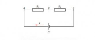
In relation to a series connection (a section of a circuit with two components), the following formulation is used:
- I = I1= I2 ;
- U = U1+ U2 ;
- R = R1+ R2
This formulation clearly demonstrates that, regardless of the number of resistive components connected in series, the current flowing through a section of the circuit does not change in value. The magnitude of the voltage applied to the effective resistive components of the circuit is the sum and totals the value of the emf source.
In this case, the voltage on each individual component is equal to: Ux = I * Rx. The total resistance should be considered the sum of the values of all resistive components in the circuit.
Circuit of parallel connected resistive elements
In the case when there is a parallel connection of resistive components, the following formulation is considered fair in relation to the law of the German physicist Ohm:
- I = I1+ I2 … ;
- U = U1= U2 … ;
- 1 / R = 1 / R1+ 1 / R2 + …
Options for creating circuit sections of a “mixed” type, when parallel and serial connections are used, are not excluded. For such options, the calculation is usually carried out by initially calculating the resistive rating of the parallel connection. Then the value of the resistor connected in series is added to the result obtained.
Integral and differential forms of the law
All of the above points with calculations are applicable to conditions when conductors of, so to speak, “homogeneous” structure are used in electrical circuits. Meanwhile, in practice, one often has to deal with the construction of schematics, where the structure of the conductors changes in different sections. For example, wires of a larger cross-section or, conversely, a smaller one, made from different materials, are used.
To take into account such differences, there is a variation of the so-called “differential-integral Ohm’s law.” For an infinitesimal conductor, the current density level is calculated depending on the voltage and conductivity value.
For the differential calculation, the formula is taken: J = ό * E. For the integral calculation, accordingly, the formulation is: I * R = φ1 – φ2 + έ However, these examples are rather closer to the school of higher mathematics and are not actually used in the real practice of a simple electrician.
Practical use
In most cases, the internal resistance of the current source is considered to be relatively small compared to that found in the electrical circuit. In this case, Ohm's law for a closed circuit is applied in an abbreviated formulation: I = U / R.
To better understand what physical processes occur in an electrical circuit, you need to consider the following:
- Processes are observed in the current source that lead to the formation of a potential difference at the terminals. When an electrical circuit is connected to them, current flows through it. It is generally accepted that it passes from a positive potential to a negative one.
- Current is the ordered movement of electrons. The substance contains a huge number of these particles, which move at high speed from negative to positive potential.
- The speed of electrons depends on the material of the conductor through which they pass, on its cross-section and length. If the latter is doubled, it will double the resistance.
Resistors are used in an electrical circuit in cases where a strictly defined resistance is required for the operation of the device. If the terminals of the current source, in simple words, are connected directly, then the resistance will be small and the current will be relatively large. On the one hand, high current in some cases can melt the wire; on the other hand, it leads to accelerated battery discharge.
In matter, the movement of electrons is not free. When moving, particles must overcome resistance, expending their energy to do so. The amount of resistance depends on the specific material. In conductors, electrons move relatively easily. No current can pass through insulators unless a voltage so high is applied that the situation creates a breakdown.
Semiconductors undergo more complex processes because they have a rigid crystal structure. In the presence of certain types of impurities, electron or hole conductivity can occur. Current can represent the movement of both electrons and holes.
A more accurate resistance characteristic can be obtained from the following formula:
Using resistivity, you can characterize the electrical properties of a certain substance. This value represents the resistance that a piece of wire made of this material has a length of 1 m and a cross-sectional area of 1 sq. m. mm.
Nonlinear elements and circuits
Ohm's law is not a fundamental law of nature and can be applied in limited cases, for example, for most conductors. It cannot be used to calculate voltage and current in semiconductor or vacuum devices, where this dependence is not proportional and can only be determined using the current-voltage characteristic (volt-ampere characteristic). This category of elements includes all semiconductor devices (diodes, transistors, zener diodes, thyristors, varicaps, etc.) and vacuum tubes. Such elements and the circuits in which they are used are called nonlinear.
Current source resistance
Ohm's law for a complete electrical circuit and formulas for calculating its parameters characterize not only the current passing through the circuit, but also that which exists inside the current source. Ohm's law for a section of a circuit does not take into account the presence of this quantity.
The battery is responsible for the movement of electrons from the positive terminal to the negative terminal. Through an electrical circuit they are constantly moving in the opposite direction. The decrease in their number on the negative terminal and the excess on the positive terminal are constantly compensated by processes occurring inside the device.
This movement of electrons is also an electric current. In this case, the particles have to overcome the internal resistance of the current source. As the temperature increases, the resistance may change, the nature of the change depends on the specific material.
Voltage, Current and Resistance
An electrical circuit is formed when a conductive path is created that allows electrical charge to travel continuously. This continuous movement of electric charge through the conductors of a circuit is called current, and is often spoken of as a “flow,” like the flow of liquid through a hollow pipe.
The force that causes charge carriers to “flow” through a circuit is called voltage. Voltage is a special measure of potential energy that is always relative between two points. When we talk about a certain amount of voltage present in a circuit, we are talking about the measurement of the potential energy to move charge carriers from one specific point in that circuit to another specific point. Without mentioning two specific points, the term "tension" has no meaning.
Current generally passes through conductors with some degree of friction or resistance to movement. This opposition to movement is more correctly called resistance. The amount of current in the circuit depends on the amount of voltage and the amount of resistance in the circuit that prevents the passage of current. Like voltage, resistance is a quantity measured between two points. For this reason, voltage and resistance values are often specified as "between" two points in a circuit.
Empirical nature of Ohm's law
When studying the nature of electricity through scientific research, certain laws are formulated. They differ from each other not only in their content, but also in how they were derived. Some laws are a consequence of more general statements, others are a successful attempt to explain repeatedly observed facts.
Ohm's law for a homogeneous area is actually an attempt to create a rule that fits a large number of observations and experiments. Its formulation has been confirmed in practice over the centuries, acquiring the force of a fundamental law of physics. Ohm's law, presented in integral form, makes it possible to perform calculations for various electrical circuits.
Converted formulas of Ohm's Law and Joule-Lenz
I came across a picture on the Internet in the form of a round tablet, in which the formulas of Ohm’s Law and Joule-Lenz’s Law and options for mathematical transformation of the formulas are successfully placed. The plate represents four sectors that are not interconnected and is very convenient for practical use
Using the table, it is easy to select a formula for calculating the required parameter of the electrical circuit using two other known ones. For example, you need to determine the current consumption of a product based on the known power and voltage of the supply network. Looking at the table in the current sector, we see that the formula I=P/U is suitable for calculation.
And if you need to determine the supply voltage U based on the power consumption P and the current I, then you can use the formula of the lower left sector, the formula U=P/I will do.
The quantities substituted in the formulas must be expressed in amperes, volts, watts or Ohms.
Use for AC
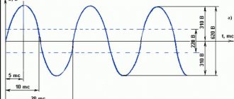
As is known, in an alternating current circuit there is both active and reactive resistance. The first of them coincides with how this quantity was understood in the time of Georg Ohm. However, inductive and capacitive reactance also inhibit the movement of electrons. In this case, Ohm's law for alternating current applies.
To use this law in such circuits, instead of ohmic resistance, total resistance should be considered, which takes into account the total effect of the active and reactive components of the resistance.
In the presented circuit, the total resistance is denoted as Z. Ohmic, inductive and capacitive - R, XL and XC, respectively. Ohm's law for an alternating current circuit takes into account all these variations. The calculation formula implies that the addition of resistances occurs according to the vector rule.
To determine all resistances, a right triangle is used, one leg of which expresses the active resistance, and the second - the reactive one. The latter is equal to the difference between inductive and capacitive reactances. The determination of the total is carried out according to the Pythagorean theorem, according to which the length of the hypotenuse is equal to the square root of the sum of the squares of the legs.
Analyzing simple circuits using Ohm's law
Let's see how these formulas work to help us analyze simple circuits:
Figure 1 – Example of a simple circuit
In the above circuit, there is only one voltage source (the battery on the left) and only one current resistance source (the lamp on the right). This makes it very easy to apply Ohm's law. If we know the values of any two of the three quantities (voltage, current, and resistance) in this circuit, we can use Ohm's law to determine the third.
In this first example, we will calculate the amount of current (I) in the circuit, given the voltage (E) and resistance (R) values:
Figure 2 - Example 1. Source voltage and lamp resistance are known
What is the current (I) in this circuit?
In the second example, we will calculate the value of resistance (R) in the circuit, given the values of voltage (E) and current (I):
Figure 3 – Example 2. Source voltage and current in the circuit are known
What resistance (R) does the lamp provide?
In the last example, we will calculate the amount of voltage supplied by the battery, taking into account the current (I) and resistance (R) values:
Figure 4 - Example 3. The current in the circuit and the lamp resistance are known
What voltage does the battery provide?
Application in practice
When you need to work with an electrical circuit, it is important to know the voltage, current, resistance in the entire circuit or in individual sections. If two of these quantities are known, then using Georg Ohm's law you can find out the third without making direct measurements.
Sometimes it is necessary to use Ohm's law for a non-uniform section of a circuit. In this case, it is divided into separate zones and calculations are first carried out for them.
Since thermal or chemical effects depend on electrical parameters, applying Ohm's law you can calculate the possible effect. In particular, knowledge of such features allows you to avoid the destructive effect of too high a current.
Ohm's law can be expressed in integral and differential forms. In the first case, we are talking about the traditional formulation, and its expression in differential form takes into account specific conductivity - the reciprocal of resistivity.
In conclusion, it should be said that resistance measurement is carried out using a special device - an ohmmeter. But this is impossible to do in a working circuit. You can determine the resistance value without disconnecting the circuit by calculation using Ohm's law and by first measuring the voltage and current in the desired section of the circuit.
What does Ohm's law sound like for a section of a circuit?
If we talk about the official formulation, then Ohm’s law can be stated as follows:
Current strength has a direct relationship with voltage and an inverse relationship with resistance. This statement is true for a section of a circuit with some specific and stable resistance.
The formula for this dependence is in the figure. Here I is the current, U is the voltage, R is the resistance.
Ohm's law formula
- The higher the voltage, the higher the current.
- The greater the resistance, the less current.
It is not so easy to imagine the meaning of this expression. After all, electricity cannot be seen. We only know approximately what it is. Let's try to understand the meaning of this law with the help of analogies.
Where and when can Ohm's law be applied?
Ohm's law in the form mentioned is valid within fairly wide limits for metals. It is carried out until the metal begins to melt. A less wide range of applications is in solutions (melts) of electrolytes and in highly ionized gases (plasma).
When working with electrical circuits, sometimes you need to determine the voltage drop across a certain element. If it is a resistor with a known resistance value (it is marked on the case), and the current passing through it is also known, you can find out the voltage using Ohm’s formula without connecting a voltmeter.
Capacitance
Let us assume that a capacitor of capacitance $C$ is included in a section of the circuit, and $R=0$ and $L=0$. We will consider the current strength ($I$) to be positive if it has the direction indicated in Fig. 2. Let the charge on the capacitor be equal to $q$.
Figure 2.
We can use the following relationships:
If $I(t)$ is defined by equation (1), then the charge is expressed as:
where $q_0$ is an arbitrary constant charge of the capacitor, which is not associated with current fluctuations, so we can assume that $q_0=0.$ We obtain the voltage equal to:
Formula (6) shows that voltage fluctuations on a capacitor lag behind current fluctuations in phase by $frac{pi }{2}.$ The voltage amplitude across the capacitor is equal to:
The quantity $X_C=frac{1}{omega C}$ is called reactive capacitance (capacitance, apparent resistance of a capacitance). If the current is constant, then $X_C=infty $. This means that no direct current flows through the capacitor. From the definition of capacitance it is clear that at high oscillation frequencies, small capacitances are small resistances to alternating current.
Do you need advice on your academic work? Ask your teacher a question and get an answer in 15 minutes! Ask a Question
Scope of application
Ohm's law is not a basic law in physics, it is just a convenient dependence of some values on others, which is suitable in almost any practical situation. Therefore, it will be easier to list situations when the law may not work:
- If there is inertia of charge carriers, for example in some high-frequency electric fields;
- In superconductors;
- If the wire heats up to such an extent that the current-voltage characteristic ceases to be linear. For example, in incandescent lamps;
- In vacuum and gas radio tubes;
- In diodes and transistors.
Interesting read: instructions on how to ring a transistor.
Inductive reactance
Let a section of the circuit have only inductance (Fig. 3). We will assume $I>0$ if the current is directed from $a$ to $b$.
Figure 3.
If a current flows in the coil, then a self-inductive emf appears in the inductance, therefore, Ohm’s law will take the form:
By condition $R=0. The mathcal E$ of self-induction can be expressed as:
From expressions (8), (9) it follows that:
The voltage amplitude in this case is equal to:
where $X_L is $inductive reactance (apparent inductive resistance).
