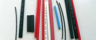
It is impossible to determine the resistance value of a resistor “by eye” by size. Various technologies are used for their production; they can have different sizes with the same characteristics. So size is definitely not an indicator in this matter. To determine the value, there is a marking of resistors. Moreover, it may be alphanumeric, or perhaps color. We will talk about what all these letters, numbers, and colored stripes mean.
The alphanumeric marking of permanent resistors is a legacy of the USSR. Now this method is not used, but the element base still exists; there are many such elements in old equipment that is many years old, but which still works. When repairing these “rarities,” you often have to change the resistance, and for this you will have to deal with this type of marking.
There are two types of resistor markings - alphanumeric and color
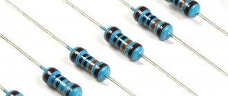
More “modern” resistors are color-coded (sometimes called “colored”). Stripes of a certain color are painted on the body of the element. Depending on the number of stripes and their position, the nominal value is calculated and the tolerance (permissible error in the resistance value) is determined. Let's figure out how to read the markings. It can be applied to any type of resistor, so it’s useful to understand the topic.
Methods for determining resistor resistance
If there is no alphanumeric marking, you can use one of the following methods:
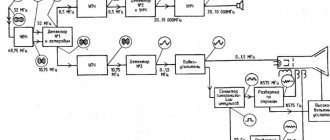
- The simplest method is to determine the denomination from the documentation. This is easiest to do if the part is purchased separately and has an accompanying document. If a resistor is part of an electrical apparatus, then its characteristics are indicated on the general electrical diagram either directly next to it (to the right or below) or below in the specification.
- If the resistor is a separate part, then its resistance can be measured with an ohmmeter or multimeter.
- It is possible to accurately identify a part contained in the device only after it has been desoldered.
Alphanumeric marking of resistors
The simplest in terms of evaluation is the Soviet resistor, its power rating is marked directly on the case with the marking MLT-1 and so on, where the unit of measurement is power, and MLT is the type of resistors most popular in Soviet times, and this abbreviation means that the resistor is M - metal film, L-varnished, T-heat-resistant. The power of such resistors depends on their size; the larger the resistor, the more power it can dissipate. These resistors are already an endangered species; they can be found in old electronic equipment.
For MLT type resistors, the unit of measurement of resistance, like others, is Ohms, they are designated as R and E. The exact size of power is indicated by the additional letter “K” - kilo-ohms or the letter “M” - mega-ohms, the measurement system here is quite simple. For example: 33E is 33 Ohms, and 47K is 47 kOhms, respectively, 1M2 is 1.2 Megaohms and so on.
If there is only a number without a letter, then they mean that this resistance is in Ohms, and the tolerance with this designation is 20%. For example, if the number 10 is written, then you have a resistor with a resistance of 10 ohms, and the tolerance is 20%.
Examples of alphanumeric markings of resistors
3E9I or 3R9 means that the resistance is 3.9 Ohms, tolerance 5%
2K2I means that the resistance is 2.2 kOhm, tolerance 5%
5K1S means that the resistance is 5.1 kOhm, tolerance is 10%
Resistor marking calculator
I really liked the Resistor 2.2 program. (Or use our online version of the calculator) Even a preschooler can figure out this program. Let's use it to determine the value of our resistor. We drive in the strips of the resistor we are interested in and the program will give us its value.
And at the bottom left in the frame we see the resistor value: 1kOhm -+5%. Convenient isn't it?
Now let's measure the resistance using a multimeter: 971 ohms. 5% of 1000 ohms is 50 ohms. This means that the resistor value must be in the range from 950 Ohms to 1050 Ohms, otherwise it can be considered unsuitable. As we can see, the value of 971 Ohms fits perfectly into the range from 950 to 1050 Ohms. Consequently, we have correctly determined the value of the resistor, and it can be safely used for our purposes.
Let's practice and determine the value of another resistor.
All OK ;-).
Which side to count the stripes on the resistor?
The resistance of the resistor is determined by the first color rings:
- For elements with three stripes, the first two colors are numbers, and the third color is the multiplier.
- For elements with four stripes, the first two colors are numbers, the third color is the multiplier, and the fourth color is the permissible deviation of the resistor resistance from its nominal value.
- For elements with five stripes, the first three colors are numbers, the fourth color is the multiplier, and the fifth color is the permissible deviation of the resistor resistance from its nominal value.
- For elements with six stripes, the first three colors are numbers, the fourth color is the multiplier, the fifth color is the permissible deviation of the resistor resistance from its nominal value, and the sixth is the temperature coefficient.
The color markings on resistors are read from left to right. In this case, you need to correctly determine the left side. As a rule, the first stripe is applied closer to one of the resistor terminals. If the element is small in size and it is impossible to maintain the required proportions for marking delimitation, then the counting is based on the color stripe, which is the widest in comparison with the others.
Additionally, it can be noted that silver and gold colors are never used to indicate the first stripes on resistors. And, as can be seen from the calculation tables, digital values are not specified for these colors.
Color marking on the resistor housing
When it appeared, I tried to remember the color marking and even memorize it - but nothing good came of it, I still got confused, and the resistor value had to be determined with a tester. Now I don’t remember when, but in one magazine I came across an article on how this whole thing can be avoided. There they talked about a cheat sheet made in the form of a resistor, only instead of colored stripes there are wheels on which the colors involved in designating the resistor values are written. Let's just look at the example shown in the photograph. Let's say we have a resistor with the following colors: green - blue - red. We need to determine its value:
Material on the topic: the device of a trimming resistor.
With the first wheel you select the color of the first stripe (green), with the second wheel you select the color of the second stripe (blue), and with the third wheel you select the color of the third stripe (red) - this will be our multiplier. Now we multiply the resulting figure in the first two windows, and we got 56, by the factor obtained in the third window - that’s ten squared or 100. The result is 5600 Ohms or 5.6 kOhms. As you can see, the cheat sheet is very simple to use.
Color marking of domestic resistors
The end result will always be in Ohms, but it is not difficult to convert it to kiloohms or megaohms:
1000 Ohm is 1 kOhm; 10000 Ohm is 10 kOhm; 100000 Ohm is 100 kOhm; 1000 kOhm is 1 megaohm or 1,000,000 Ohms; 10 M is 10000 kOhm or 10000000 Ohm.
To make it, I used cardboard, but you can use any other material that is easy to process. If you use cardboard, then for strength it is advisable to glue it in two layers. I didn’t draw a drawing, but indicated all the dimensions directly on the cheat sheet, because it’s easier for me, and it’s clearer for you. Dimensions are indicated in millimeters.
The next step is to make three wheels. The first two will be the same, and they are marked with the colors of the stripes and the numbers corresponding to each color. The wheel must be divided into ten equal parts, and if you look at the right one, you can see that, for example, brown corresponds to one, and black corresponds to zero.
The sequence is:
- Black – 0;
- Brown – 1;
- Red – 2;
- Orange – 3;
- Yellow – 4;
- Green – 5;
- Blue – 6;
- Purple – 7;
- Gray – 8;
- White – 9.
Resistor with markings
Here the sequence is:
- Black – 1;
- Brown – 10;
- Red – 10 to the power of 2 (100);
- Orange – 10 to the power of 3 (1000);
- Yellow – 10 to the power of 4 (10000);
- Green – 10 to the power of 5 (100000);
- Blue – 10 to the power of 6 (1000000); Purple – 10 to the power of 7 (10000000);
- Gray – 10 to the power of 8 (100000000);
- White – 10 to the power of 9 (1000000000);
- Golden – 10 to the power of -1 (0.1);
- Silver – 10 to the power of -2 (0.01).
It will be interesting➡ How is parallel and series connection of resistors different?
Secure the wheels with bolts with a diameter of 3 mm. In any case, if all else fails, the resistance of the resistor can always be measured with a multimeter. If you have any doubts about determining the band of the first number, refer to the tolerance band, which is located on the right side of the resistor. As a rule, the bulk of resistors come with a tolerance of five and ten percent, and these are golden and silver colors.
Resistor in the diagram
Resistor marking calculator with three and four stripes
To determine the resistance of three-band resistors, use the four-band element calculator below. The only peculiarity is that for resistors with three strips the tolerance (error) is always ±20%.
Resistor calculator with four colored stripes:
| 1st lane | 2nd lane | Decimal multiplier | Tolerance | |
| Silver | ÷100 | ±10% | ||
| Gold | ÷10 | ±5% | ||
| Black | 0 | 0 | x1 | |
| Brown | 1 | 1 | x10 | ±1% |
| Red | 2 | 2 | x100 | ±2% |
| Orange | 3 | 3 | x1K | |
| Yellow | 4 | 4 | x10K | |
| Green | 5 | 5 | x100K | ±0.5% |
| Blue | 6 | 6 | x1M | ±0.25% |
| Violet | 7 | 7 | x10M | ±0.10% |
| Grey | 8 | 8 | x100M | ±0.05% |
| White | 9 | 9 | x1G |
| Result: | ± | % |
Code and color marking of resistors
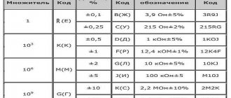
The coded designation of the nominal resistance of resistors consists of three or four characters, including two numbers and a letter or three numbers and a letter. The code letter is a multiplier indicating the resistance in Ohms and determines the position of the decimal point. The coded designation of the permissible deviation consists of a letter of the Latin alphabet (see tables).
Coded designation of nominal resistance, tolerance and designation examples.
| Notation examples | |
| Full designation | Code |
| 3.9 ohms ± 5% | 3R9J |
| 215 ohms ± 2% | 215RG |
| 1 kΩ ± 5% | 1K0J |
| 12.4 kΩ ± 1% | 12K4F |
| 10 kΩ ± 5% | 10KJ |
| 100 kΩ ± 5% | M10J |
| 2.2 MΩ ± 10% | 2M2K |
| 6.8 GΩ ± 20% | 6G8M |
| 1 Volume ± 20% | 1T0M |
| Resistance | |
| Factor | Code |
| 1 | R(E) |
| 10^3 | K(K) |
| 10^6 | M(M) |
| 10^9 | G (G) |
| 10^12 | T (T) |
| Tolerance, % | Code |
| ± 0,001 | E |
| ± 0,002 | L |
| ± 0,005 | R |
| ± 0,01 | P |
| ± 0,02 | U |
| ± 0,05 | A |
| ± 0,1 | B (W) |
| ± 0,25 | C (U) |
| ± 0,5 | D (D) |
| ± 1 | F (P) |
| ± 2 | G (L) |
| ± 5 | J (I) |
| ± 10 | K (C) |
| ± 20 | M(V) |
| ± 30 | N (F) |
Note. The old designation is indicated in parentheses.
Color marking is applied in the form of four or five colored rings. Each color corresponds to a specific digital value.
For resistors with four colored rings, the first and second rings indicate the resistance value in Ohms, the third ring is the multiplier by which the nominal resistance value must be multiplied, and the fourth ring determines the tolerance value in percent.
| Sign color | Nominal resistance, Ohm | Tolerance, % | TKS [ppm/°C] | |||
| First digit | Second digit | Third digit | Factor | |||
| Silver | 10-2 | ±10 | ||||
| Golden | 10-1 | ±5 | ||||
| Black | 0 | 0 | 1 | |||
| Brown | 1 | 1 | 1 | 10 | ±1 | 100 |
| Red | 2 | 2 | 2 | 102 | ±2 | 50 |
| Orange | 3 | 3 | 3 | 103 | 15 | |
| Yellow | 4 | 4 | 4 | 104 | 25 | |
| Green | 5 | 5 | 5 | 105 | 0,5 | |
| Blue | 6 | 6 | 6 | 106 | ±0,25 | 10 |
| Violet | 7 | 7 | 7 | 107 | ±0,1 | 5 |
| Grey | 8 | 8 | 8 | 108 | ±0,05 | |
| White | 9 | 9 | 9 | 109 | 1 | |
Note. Ppm – parts per million – part per million, number of parts per million, 1/106
Resistors with a small tolerance value (0.1%...2%) are marked with five color rings. The first three are the numerical value of the resistance, the fourth is the multiplier, the fifth is the tolerance. In the marking of resistors adopted on (see below), the last ring can be TKS.
The markings on the resistors are shifted to one of the terminals and are located from left to right. If the dimensions of the resistor do not allow the marking to be placed closer to one of the terminals, the width of the stripe of the first sign is made approximately twice as large as the others. However, this requirement is not always met; in this case, we try to determine the denomination, the value of which falls into the standard series:
The nominal resistance of resistors is selected from six standard rows (E3, E6, E12, E24, E48, E96 and E192) in accordance with GOST 2825-67.
Each row corresponds to a certain tolerance in the part ratings. Thus, parts from the E6 series have a permissible deviation from the nominal value of ±20%, from the E12 series - ±10%, from the E24 series - ±5%. Actually, the rows are arranged in such a way that the next value differs from the previous one by slightly less than double tolerance. Nominal ranges E6, E12, E24
| E6 | E12 | E24 | E6 | E12 | E24 | E6 | E12 | E24 | ||
| 1,0 | 1,0 | 1,0 | 2,2 | 2,2 | 2,2 | 4,7 | 4,7 | 4,7 | ||
| 1,1 | 2,4 | 5,1 | ||||||||
| 1,2 | 1,2 | 2,7 | 2,7 | 5,6 | 5,6 | |||||
| 1,3 | 3,0 | 6,2 | ||||||||
| 1,5 | 1,5 | 1,5 | 3,3 | 3,3 | 3,3 | 6,8 | 6,8 | 6,8 | ||
| 1,6 | 3,6 | 7,5 | ||||||||
| 1,8 | 1,8 | 3,9 | 3,9 | 8,2 | 8,2 | |||||
| 2,0 | 4,3 | 9,1 |
The E48 series corresponds to a relative accuracy of ±2%, E96 - ±1%, E192 - ±0.5%.
The elements of the series form a strict geometric progression with denominators 101/48 ≈ 1.04914, 101/96 ≈ 1.024275, 101/192 ≈ 1.01206483 and can easily be calculated on a calculator. Nominal series E48, E96, E192
| E48 | E96 | E192 | E48 | E96 | E192 | E48 | E96 | E192 | E48 | E96 | E192 | E48 | E96 | E192 | E48 | E96 | E192 | |||||
| 1,00 | 1,00 | 1,00 | 1,47 | 1,47 | 1,47 | 2,15 | 2,15 | 2,15 | 3,16 | 3,16 | 3,16 | 4,64 | 4,64 | 4,64 | 6,81 | 6,81 | 6,81 | |||||
| 1,01 | 1,49 | 2,18 | 3,20 | 4,70 | 6,90 | |||||||||||||||||
| 1,02 | 1,02 | 1,50 | 1,50 | 2,21 | 2,21 | 3,24 | 3,24 | 4,75 | 4,75 | 6,98 | 6,98 | |||||||||||
| 1,04 | 1,52 | 2,23 | 3,28 | 4,81 | 7,06 | |||||||||||||||||
| 1,05 | 1,05 | 1,05 | 1,54 | 1,54 | 1,54 | 2,26 | 2,26 | 2,26 | 3,32 | 3,32 | 3,32 | 4,87 | 4,87 | 4,87 | 7,15 | 7,15 | 7,15 | |||||
| 1,06 | 1,56 | 2,29 | 3,36 | 4,93 | 7,23 | |||||||||||||||||
| 1,07 | 1,07 | 1,58 | 1,58 | 2,32 | 2,32 | 3,40 | 3,40 | 4,99 | 4,99 | 7,32 | 7,32 | |||||||||||
| 1,09 | 1,60 | 2,34 | 3,44 | 5,05 | 7,41 | |||||||||||||||||
| 1,10 | 1,10 | 1,10 | 1,62 | 1,62 | 1,62 | 2,37 | 2,37 | 2,37 | 3,48 | 3,48 | 3,48 | 5,11 | 5,11 | 5,11 | 7,50 | 7,50 | 7,50 | |||||
| 1,11 | 1,64 | 2,40 | 3,52 | 5,17 | 7,59 | |||||||||||||||||
| 1,13 | 1,13 | 1,65 | 1,65 | 2,43 | 2,43 | 3,57 | 3,57 | 5,23 | 5,23 | 7,68 | 7,68 | |||||||||||
| 1,14 | 1,67 | 2,46 | 3,61 | 5,30 | 7,77 | |||||||||||||||||
| 1,15 | 1,15 | 1,15 | 1,69 | 1,69 | 1,69 | 2,49 | 2,49 | 2,49 | 3,65 | 3,65 | 3,65 | 5,36 | 5,36 | 5,36 | 7,87 | 7,87 | 7,87 | |||||
| 1,17 | 1,72 | 2,52 | 3,70 | 5,42 | 7,96 | |||||||||||||||||
| 1,18 | 1,18 | 1,74 | 1,74 | 2,55 | 2,55 | 3,74 | 3,74 | 5,49 | 5,49 | 8,06 | 8,06 | |||||||||||
| 1,20 | 1,76 | 2,58 | 3,79 | 5,56 | 8,16 | |||||||||||||||||
| 1,21 | 1,21 | 1,21 | 1,78 | 1,78 | 1,78 | 2,61 | 2,61 | 2,61 | 3,83 | 3,83 | 3,83 | 5,62 | 5,62 | 5,62 | 8,25 | 8,25 | 8,25 | |||||
| 1,23 | 1,80 | 2,64 | 3,88 | 5,69 | 8,35 | |||||||||||||||||
| 1,24 | 1,24 | 1,82 | 1,82 | 2,67 | 2,67 | 3,92 | 3,92 | 5,76 | 5,76 | 8,45 | 8,45 | |||||||||||
| 1,26 | 1,84 | 2,71 | 3,97 | 5,83 | 8,56 | |||||||||||||||||
| 1,27 | 1,27 | 1,27 | 1,87 | 1,87 | 1,87 | 2,74 | 2,74 | 2,74 | 4,02 | 4,02 | 4,02 | 5,90 | 5,90 | 5,90 | 8,66 | 8,66 | 8,66 | |||||
| 1,29 | 1,89 | 2,77 | 4,07 | 5,97 | 8,76 | |||||||||||||||||
| 1,30 | 1,30 | 1,91 | 1,91 | 2,80 | 2,80 | 4,12 | 4,12 | 6,04 | 6,04 | 8,87 | 8,87 | |||||||||||
| 1,32 | 1,93 | 2,84 | 4,17 | 6,12 | 8,98 | |||||||||||||||||
| 1,33 | 1,33 | 1,33 | 1,96 | 1,96 | 1,96 | 2,87 | 2,87 | 2,87 | 4,22 | 4,22 | 4,22 | 6,19 | 6,19 | 6,19 | 9,09 | 9,09 | 9,09 | |||||
| 1,35 | 1,98 | 2,91 | 4,27 | 6,26 | 9,19 | |||||||||||||||||
| 1,37 | 1,37 | 2,00 | 2,00 | 2,94 | 2,94 | 4,32 | 4,32 | 6,34 | 6,34 | 9,31 | 9,31 | |||||||||||
| 1,38 | 2,03 | 2,98 | 4,37 | 6,42 | 9,42 | |||||||||||||||||
| 1,40 | 1,40 | 1,40 | 2,05 | 2,05 | 2,05 | 3,01 | 3,01 | 3,01 | 4,42 | 4,42 | 4,42 | 6,49 | 6,49 | 6,49 | 9,53 | 9,53 | 9,53 | |||||
| 1,42 | 2,08 | 3,05 | 4,48 | 6,57 | 9,65 | |||||||||||||||||
| 1,43 | 1,43 | 2,10 | 2,10 | 3,09 | 3,09 | 4,53 | 4,53 | 6,65 | 6,65 | 9,76 | 9,76 | |||||||||||
| 1,45 | 2,13 | 3,12 | 4,59 | 6,73 | 9,88 |
The resistance of a resistor is obtained by multiplying a number from the standard series by 10^n, where n is a positive or negative integer.
Marking of Soviet resistors
First of all, let's deal with Soviet resistors.
No matter what you do, you cannot escape from Soviet electronics. Therefore, a little theory will not harm you.
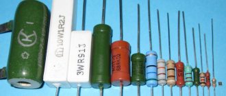
At first glance, we must estimate what maximum power the resistor can dissipate. From top to bottom, below in the photo, resistors by power: 2 Watt, 1 Watt, 0.5 Watt, 0.25 Watt, 0.125 Watt. On resistors with a power of 1 and 2 Watts they write MLT-1 and MLT-2, respectively.
MLT is a type of the most common Soviet resistors, from the abbreviated names Metal Film, Lacquered, Heat Resistant. For other resistors, the power can be estimated based on their dimensions. The larger the resistor, the more power it can dissipate into the surrounding space.
Units of measurement in MLTs - Ohms - are designated as R or E. Kilo-ohms - with the letter “K”, Mega-ohms with the letter “M”. Everything is simple here. For example, 33E (33 Ohms); 33R (33 Ohm); 47K (47 kOhm); 510K (510 kOhm); 1.0M (1 MOhm). There is also a trick that letters can precede numbers, for example, K47 means that the resistance is 470 Ohms, M56 - 560 Kilohms. And sometimes, in order not to bother with commas, they stupidly push a letter there, for example. 4K3 = 4.3 Kilohm, 1M2 – 1.2 Megaohm.
Let's look at our hero. Let's look immediately at the designation. 1K0 or in the words “one and zero”. This means that its resistance should be 1.0 Kilohm.
Let's see if this is really true?
Well, yes, everything agrees with a small error.
SMD resistors - marking the nominal values of SMD resistors
SMD resistors - marking of chip resistors
SMD resistors - the markings of which are of interest to many radio amateurs. These resistors are manufactured in miniature packages, usually made of ceramic and intended for surface mounting. This element is the most common component in modern electronic circuits.
Various companies producing SMD resistors make many different modifications of their products, code designations of which differ from others. In this regard, electronics engineers who often have to repair electronic equipment or assemble printed circuit boards need to clearly know the code designations of resistors.
Purpose of chip resistors
The main function of resistors in a circuit is to limit current in a specific part of the electrical path. One of the closest examples that can be used to show a resistor in action is the inclusion of resistance in the supply circuit of LED diodes or in the emitter circuit of a bipolar transistor installed in the amplifying stage. The table below will greatly assist you in deciphering the codes.
Table of decoding nominal values of SMD resistors
| Code smd | Meaning | Code smd | Meaning | Code smd | Meaning | Code smd | Meaning |
| R10 | 0.1 Ohm | 1R0 | 1 ohm | 100 | 10 ohm | 101 | 100 Ohm |
| R11 | 0.11 Ohm | 1R1 | 1.1 Ohm | 110 | 11 ohm | 111 | 110 Ohm |
| R12 | 0.12 Ohm | 1R2 | 1.2 Ohm | 120 | 12 ohm | 121 | 120 Ohm |
| R13 | 0.13 Ohm | 1R3 | 1.3 Ohm | 130 | 13 ohm | 131 | 130 Ohm |
| R15 | 0.15 Ohm | 1R5 | 1.5 Ohm | 150 | 15 ohm | 151 | 150 Ohm |
| R16 | 0.16 Ohm | 1R6 | 1.6 Ohm | 160 | 16 ohm | 161 | 160 Ohm |
| R18 | 0.18 Ohm | 1R8 | 1.8 Ohm | 180 | 18 ohm | 181 | 180 Ohm |
| R20 | 0.2 Ohm | 2R0 | 2 ohm | 200 | 20 ohm | 201 | 200 Ohm |
| R22 | 0.22 Ohm | 2R2 | 2.2 Ohm | 220 | 22 Ohm | 221 | 220 Ohm |
| R24 | 0.24 Ohm | 2R4 | 2.4 Ohm | 240 | 24 ohm | 241 | 240 Ohm |
| R27 | 0.27 Ohm | 2R7 | 2.7 Ohm | 270 | 27 Ohm | 271 | 270 Ohm |
| R30 | 0.3 ohm | 3R0 | 3 ohm | 300 | 30 ohm | 301 | 300 Ohm |
| R33 | 0.33 Ohm | 3R3 | 3.3 Ohm | 330 | 33 Ohm | 331 | 330 Ohm |
| R36 | 0.36 Ohm | 3R6 | 3.6 Ohm | 360 | 36 Ohm | 361 | 360 Ohm |
| R39 | 0.39 Ohm | 3R9 | 3.9 Ohm | 390 | 39 Ohm | 391 | 390 Ohm |
| R43 | 0.43 Ohm | 4R3 | 4.3 Ohm | 430 | 43 Ohm | 431 | 430 Ohm |
| R47 | 0.47 Ohm | 4R7 | 4.7 Ohm | 470 | 47 Ohm | 471 | 470 Ohm |
| R51 | 0.51 Ohm | 5R1 | 5.1 Ohm | 510 | 51 Ohm | 511 | 510 Ohm |
| R56 | 0.56 Ohm | 5R6 | 5.6 Ohm | 560 | 56 Ohm | 561 | 560 Ohm |
| R62 | 0.62 Ohm | 6R2 | 6.2 Ohm | 620 | 62 Ohm | 621 | 620 Ohm |
| R68 | 0.68 Ohm | 6R8 | 6.8 Ohm | 680 | 68 Ohm | 681 | 680 Ohm |
| R75 | 0.75 Ohm | 7R5 | 7.5 Ohm | 750 | 75 Ohm | 751 | 750 Ohm |
| R82 | 0.82 Ohm | 8R2 | 8.2 Ohm | 820 | 82 Ohm | 821 | 820 Ohm |
| R91 | 0.91 Ohm | 9R1 | 9.1 Ohm | 910 | 91 Ohm | 911 | 910 Ohm |
| Code smd | Meaning | Code smd | Meaning | Code smd | Meaning | Code smd | Meaning |
| 102 | 1 kOhm | 103 | 10 kOhm | 104 | 100 kOhm | 105 | 1 MOhm |
| 112 | 1.1 kOhm | 113 | 11 kOhm | 114 | 110 kOhm | 115 | 1.1 MOhm |
| 122 | 1.2 kOhm | 123 | 12 kOhm | 124 | 120 kOhm | 125 | 1.2 MOhm |
| 132 | 1.3 kOhm | 133 | 13 kOhm | 134 | 130 kOhm | 135 | 1.3 MOhm |
| 152 | 1.5 kOhm | 153 | 15 kOhm | 154 | 150 kOhm | 155 | 1.5 MOhm |
| 162 | 1.6 kOhm | 163 | 16 kOhm | 164 | 160 kOhm | 165 | 1.6 MOhm |
| 182 | 1.8 kOhm | 183 | 18 kOhm | 184 | 180 kOhm | 185 | 1.8 MOhm |
| 202 | 2 kOhm | 203 | 20 kOhm | 204 | 200 kOhm | 205 | 2 MOhm |
| 222 | 2.2 kOhm | 223 | 22 kOhm | 224 | 220 kOhm | 225 | 2.2 MOhm |
| 242 | 2.4 kOhm | 243 | 24 kOhm | 244 | 240 kOhm | 245 | 2.4 MOhm |
| 272 | 2.7 kOhm | 273 | 27 kOhm | 274 | 270 kOhm | 275 | 2.7 MOhm |
| 302 | 3 kOhm | 303 | 30 kOhm | 304 | 300 kOhm | 305 | 3 MOhm |
| 332 | 3.3 kOhm | 333 | 33 kOhm | 334 | 330 kOhm | 335 | 3.3 MOhm |
| 362 | 3.6 kOhm | 363 | 36 kOhm | 364 | 360 kOhm | 365 | 3.6 MOhm |
| 392 | 3.9 kOhm | 393 | 39 kOhm | 394 | 390 kOhm | 395 | 3.9 MOhm |
| 432 | 4.3 kOhm | 433 | 43 kOhm | 434 | 430 kOhm | 435 | 4.3 MOhm |
| 472 | 4.7 kOhm | 473 | 47 kOhm | 474 | 470 kOhm | 475 | 4.7 MOhm |
| 512 | 5.1 kOhm | 513 | 51 kOhm | 514 | 510 kOhm | 515 | 5.1 MOhm |
| 562 | 5.6 kOhm | 563 | 56 kOhm | 564 | 560 kOhm | 565 | 5.6 MOhm |
| 622 | 6.2 kOhm | 623 | 62 kOhm | 624 | 620 kOhm | 625 | 6.2 MOhm |
| 682 | 6.8 kOhm | 683 | 68 kOhm | 684 | 680 kOhm | 685 | 6.8 MOhm |
| 752 | 7.5 kOhm | 753 | 75 kOhm | 754 | 750 kOhm | 755 | 7.5 MOhm |
| 822 | 8.2 kOhm | 823 | 82 kOhm | 824 | 820 kOhm | 815 | 8.2 MOhm |
| 912 | 9.1 kOhm | 913 | 91 kOhm | 914 | 910 kOhm | 915 | 9.1 MOhm |
Marking of SMD resistors
SMD resistors
SMD resistors are miniature resistors designed for surface mounting. SMD resistors are significantly smaller than their traditional counterpart. They are often square, rectangular or oval shaped, with a very low profile.
Electric soldering iron with temperature control Power: 60/80 W, temperature: 200'C-450'C, quality… Read more
Instead of the lead wires of conventional resistors that are inserted into holes on a printed circuit board, SMD resistors have small contacts that are soldered to the surface of the resistor body. This eliminates the need to make holes in the printed circuit board, and thus allows more efficient use of its entire surface.
Why do we need resistor markings?
Considering the fact that SMD resistors are small in size, they cannot be color coded, so manufacturers have developed a different marking method. As a rule, the designation of smd resistors contains three or four numbers; letters may be present.
- Digital marking of resistors is necessary in order to indicate the numerical value of the resistance of the resistor, the last digit is a multiplier. It can also indicate the power that must be raised to 10 to get the final result. For example, resistance can be determined this way: 450 = 45 x 10 equals 45 Ohms.
- If the marking is EIA-96, then this means that the resistors are high precision. This standard is intended for resistors that have a small resistance of 1%. This marking system has three elements: 2 numbers that indicate the denomination code, and the letters are a multiplier. The numbers are a code that gives the resistance number. For example, code 04 may indicate 107 ohms.
For convenient calculation, a calculator is used that will help you quickly find the resistance value. To calculate, you need to enter the code that is on the component and the resistance will immediately appear below. This calculator is suitable not only for the standard. To more accurately check the resistance, it is best to use a multimeter for calculations. Read here which is the best multimeter to choose.
What characteristics does it show?
The most important characteristics of the parts are the value of the nominal resistance, the tolerance on the value and the temperature coefficient. Any of these characteristics is related to the power of SMD resistors and the resistance between it and the ambient temperature. In some areas, even noise characteristics are taken into account.
Important! Component characteristics include stability, voltage, resistance dependence and frequency parameters.
To understand this issue in detail, you need to carefully study all the characteristics:
- The value of the nominal resistance. The tolerance on the nominal resistance value is specified as a percentage. This value indicates the resistance of the resistor under external influences on it.
- Temperature. As a rule, the natural temperature is +20°C and there should be normal atmospheric pressure. SMD resistors are produced with a tolerance for nominal resistance ranging from ±0.05% to ±5%.
- Accuracy. The most accurate resistors can be considered those that are calculated using the formula TKS=DR/(R*DT). DR means the change in resistance when the temperature changes by the amount DT, R is the nominal value of the resistance.
If the components can be calculated using this formula, then this means that they have the highest accuracy.
What is written on SMD resistors
For surface mounting on printed circuit boards, conventional types of resistors are inconvenient to use. Therefore, special technologies have been developed to make them small - long and a few millimeters wide. This allows you to use the board area to the maximum. But even color marking is difficult to apply on miniature resistors. Therefore, SMD resistors have their own markings - alphanumeric. There are three options for this marking:
- three digits;
- four digits;
- three numbers and a letter.
A few examples of how to calculate the value of an SMD resistor
For SMD resistors with medium error
The first two options for marking resistors - three or four digits - are used for resistors with an average error (permissible deviation 5-10%). In them, the first two or three digits are the denomination, the last determines the multiplier. This figure shows to what power 10 must be raised. For those who have problems with raising to a power, the multiplier is written in the figure below. You can also say that the last digit shows how many zeros there are in the multiplier.
Rule for decoding SMD resistance rating codes
The principle of finding the value is similar to the alphanumeric marking of Soviet resistors. The first two or three digits must be multiplied by a factor. To make it clearer, let's look at a few examples of inscriptions on SMD resistance. The multiplier can be taken from the table in the figure above.
- 480 - 48 must be multiplied by 1, that is, this is a 48 Ohm resistor;
- 313 - 31 must be multiplied by 1000, we get 31000 Ohms or 31 kOhms;
- 5442 - 544 must be multiplied by 100, for a total of 54400 Ohms or 54.4 kOhms;
- 2115 - 211 with a multiplier of 100,000, we get 21,100,000 Ohms or 21.1 MOhms.
But to mark low-resistance SMD resistors - with a resistance of less than 100 Ohms - they use a different system. Here you need to decide on the position of the point. Instead of a dot, put the Latin letter R. An example is in the picture below, it’s not difficult to figure out.
Marking of low-resistance SMD resistors
If you see the letter R on the resistor body, this means that the value is small - no more than 100 Ohms. Sometimes there is a variant with the letter K. This letter encrypts a multiplier of 10³ or 1000. This type of notation was created by analogy, that is, the position of the letter indicates the presence of a dot.
Of all the examples, only K47 is worth examining, and maybe even 4K7. The rest are easy to understand. So, K47. Since the letter comes before the numbers, we put a comma in front of them, and the multiplier is known - 1000. So we get: 0.47 * 1000 Ohm = 470 Ohm. Second example: 4K7. Since the letter is between the numbers, we put a comma here, the multiplier is still the same - 1000. We get 4.7 * 1000 = 4700 Ohm or 4.7 kOhm.
Deciphering the codes of precision SMD resistors (high precision)
Surface-mount resistors on high-precision printed circuit boards have their own markings. It is described in the EIA-96 standard. It is used for products with possible deviations in nominal value of no more than 1% (0.5%, 0.25%). On the surface of the resistor there are two numbers and one letter (not R and not K), but their meaning is different:
- two digits indicate the denomination code (note, not the denomination itself, but its code);
- letter is a multiplier.
The denomination is found in several steps. First, the code is found in the table (in the picture below), and the denomination is determined from it. Using the second part of the table, the multiplier is found (highlighted in red). The two numbers found are multiplied and the denomination is obtained.
Code decoding table for high precision SMD resistors
Let's look at a few examples of how to determine the value of precision SMD resistors.
- 01C. Code 01 means 100 Ohm, the letter C is a multiplier of 100. In total we get the nominal value: 100*100 = 10000 Ohm or 10 kOhm.
- 30S. Using the table, we look at code 30. It corresponds to the number 200. The letter S is a multiplier of 0.01. We calculate the nominal: 200 * 0.01 = 2 Ohms.
- 11D. Decoding code 11 - 127, under the letter D the multiplier of 1000 is encrypted. In total, we get 127 * 1000 = 127,000 Ohms or 127 kOhms.
In general, the principle is clear. We are looking for a code, a multiplier, and multiplying. In general, nothing particularly complicated. Simple math. If verbal counting is “not very good,” a calculator can help. Another option is to find a program that deciphers resistor codes.
Standard sizes of SMD resistors
Basically, the term frame size includes the size, shape and terminal configuration (package type) of any electronic component. For example, the configuration of a conventional chip that has a flat package with double-sided pins (perpendicular to the plane of the base) is called DIP.
SMD resistor sizes are standardized, and most manufacturers use the JEDEC standard. The size of SMD resistors is indicated by a numerical code, for example, 0603. The code contains information about the length and width of the resistor. So in our example code 0603 (in inches) the body length is 0.060 inches by 0.030 inches wide.
Organizer for SMD components Great for storing 1206/0805/0603/0402/0201... 2 in 1 soldering station with LCD display Power: 800 W, temperature: 100...480 degrees, air flow... Set of SMD resistors 1206 100 pcs., 0R…10M 1/2 W, 0, 1, 10, 100, 150, 220, 330… Professional SMD component tester Digital tester for checking SMD resistors, capacitors, diodes…
The same resistor size in the metric system will have code 1608 (in millimeters), respectively, the length is 1.6 mm, the width is 0.8 mm. To convert dimensions to millimeters, simply multiply the size in inches by 25.4.
SMD resistor sizes and their power
The size of the SMD resistor depends mainly on the required power dissipation. The following table lists the sizes and specifications of the most commonly used SMD resistors.
Marking of SMD resistors - designations and explanation
Marking of SMD resistors
The term “SMD resistor” appeared relatively recently. Surface Mounted Devices can literally be translated into Russian as “surface-mounted device.” Chip resistors, as they are also called, are used in surface-mounted printed circuit boards. They have much smaller dimensions than similar wirewound resistors. Square, rectangular or oval shape and low rise allow you to compactly place circuits and save space.
The case has contact pins, which during installation are attached directly to the tracks of the printed circuit board. This design makes it possible to fasten elements without using holes. Thanks to this, the useful area of the board is used with maximum effect, which allows reducing the dimensions of the devices.
Appearance of SMD resistors
The dimensions and shape of SMD resistors are regulated by the JEDEC regulatory document, which provides recommended sizes. Typically, SMD resistors are marked on the case, containing data on the dimensions of the resistor. For example, digital code 0804 assumes a length of 0.08 inches and a width of 0.04 inches.
If we convert this encoding to the SI system, then this SMD resistor will be designated as 2010. From this marking it can be seen that the length is 2.0 mm and the width is 1.0 mm (1 inch is equal to 2.54 mm).
The required power dissipation determines the chip size. Since it is not possible to place the standard markings found on conventional wire-wound resistors on an SMD resistor, which has a very small size, a code designation system has been developed. For convenience, manufacturers have conventionally divided chip resistors into three types according to the marking method:
- three-digit marking;
- four-digit marking;
- marking consisting of two numbers and a letter.
The latter option is used for high-precision resistors with a tolerance of 1% (precision). The very small size does not allow markings with long codes to be placed on them. The EIA-96 standard has been developed for them
To mark small resistances (less than 10 Ohms), the Latin letter “R” is used. For example: 0R1 = 0.1 Ohm and 0R05 = 0.05 Ohm.
Marking of SMD resistors
There are ratings of increased accuracy (so-called precision).
Marking of precision SMD resistors
An example of selecting the required resistor: if the number 232 is indicated, then you need to multiply 23 by 10 to the second power. This results in a resistance of 2.3 kΩ (23 x 102 = 2,300 Ω = 23 kΩ). Chips of the second type are calculated similarly.
SMD resistor designation calculator
Decoding the designation of chip resistors is a specific task. You can calculate the required value using old proven methods by performing several arithmetic operations. But progress does not stand still, and the same can be done using various sites.
The SMD resistor calculator will help you choose the right size, understand the codes, and also save you from grueling calculations. In addition, there is a special program “Resistor”. By clicking the mouse a couple of times, you can find the information you need.
Standard color coding
In order to correctly mark and tables have become widely used, international standards have been adopted, according to which from 3 to 6 stripes can be applied to a resistor, each of which has a specific purpose.
Let's consider the features of standard color marking:
- Marking with 3 stripes is carried out as follows: the first 2 rings indicate numbers, 3 – the multiplier. There is no 4 ring, since for all such resistors the accepted deviation is 20%.
- 4 rings – marking, which is slightly different from the previous case. The last ring means deviation. All values are selected using a special table. In this case, the deviation is 5%, 10%.
- 5 rings means the minimum deviation rate, up to 0.005%. In this case, the first 3 rings represent numbers, which then need to be multiplied by a factor. You can find the multiplier using the same table; you need to look for the color value of 4 rings.
- There are resistor options that have 6 rings. Their decoding is carried out in the same way as with 5 rings, only the last of them means the temperature coefficient of change. This value determines how much the resistance value will change as the temperature of the resistor body increases.
Not all tables have a column for decoding the 6th ring, which is worth considering.
Four strip resistors
1st digit2nd digitMultiplierInaccuracy1st digit1 Brown2 Red3 Orange4 Yellow5 Green6 Blue7 Purple8 Gray9 White2nd digit0 Black1 Brown2 Red3 Orange4 Yellow5 Green6 Blue7 Purple8 Gray9 WhiteMultiplierx1 Blackx10 Brownx100 Redx1k Orangex10k Yellowx100k Greenx1M Bluex10M Purplex100M Grayx1G White÷10 Gold÷100 SilverAccuracy± 1 % Brown ± 2% Red ± 3% Orange ± 4% Yellow ± 0.5% Green ± 0.25% Blue ± 0.10% Purple ± 0.05% Gray ± 5% Gold ± 10% Silver Resistance: Ohm (Ω) Accuracy: Minimum: Ohm (Ω )Maximum: Ohm (Ω)
Five strip resistors
1st digit2nd digit3rd digitMultiplierInaccuracy1st digit1 Brown2 Red3 Orange4 Yellow5 Green6 Blue7 Purple8 Gray9 White2nd digit0 Black1 Brown2 Red3 Orange4 Yellow5 Green6 Blue7 Purple8 Gray9 White3rd digit0 Black1 Brown2 Red3 Orange evy4 Yellow5 Green6 Blue7 Purple8 Gray9 WhiteMultiplierx1 Blackx10 Brownx100 Redx1k Orangex10k Yellowx100k Greenx1M Bluex10M Purplex100M Grayx1G White÷10 Gold÷100 SilverAccuracy± 1% Brown± 2% Red± 3% Orange± 4% Yellow± 0.5% Green± 0.25% Blue± 0.10% Purple ± 0.05% Gray ± 5% Gold ± 10% Silver Resistance: Ohm (Ω) Accuracy: Minimum: Ohm (Ω) Maximum: Ohm (Ω)
Six strip resistors
1st digit2nd digit3rd digitMultiplier Error TKS1st digit1 Brown2 Red3 Orange4 Yellow5 Green6 Blue7 Purple8 Gray9 White2nd digit0 Black1 Brown2 Red3 Orange4 Yellow5 Green6 Blue7 Purple8 Gray9 White3rd digit0 Black1 Brown2 Red3 Orange4 Yellow5 Green6 Blue7 Purple8 Gray9 WhiteMultiplierx1 Blackx10 Brownx100 Redx1k Orangex10k Yellowx100k Greenx1M Bluex10M Purplex100M Grayx1G White÷10 Gold÷100 SilverAccuracy± 1% Brown± 2% Red± 3% Orange± 4% Yellow± 0.5% Green± 0.25% Blue± 0.10% Purple ± 0.05% Gray ± 5% Gold ± 10% Silver TKS 100 Brown 50 Red 15 Orange 25 Yellow 10 Blue 5 Purple Resistance: Ohm (Ω) Accuracy: Minimum: Ohm (Ω) Maximum: Ohm (Ω) TKS: ppm/°C
Main sizes of SMD resistors
The limited size of the visible surface explains the minimum number of marking elements. For SMD resistors, the sizes are determined by a digital combination of 4 (5) characters. The first half of the number indicates the length, the second half the width. Previously, the measurement result was used in inches with rounding of the result. Nowadays, the metric system (mm) is more commonly used, which means relatively better accuracy.
Examples of notation
| Standard size | System (metric, inch) | Length Width | |
| In inches | In millimeters | ||
| 0201M | M | 0,0079/0,0039 | 2/1 |
| 0805 | D | 0,08/0,05 | 2,032/1,27 |
| 2550M | M | 0,098/0,197 | 2,5/5 |
| 1020 | D | 0,1/0,2 | 2,54/5,08 |
The size of a capacitor, an LED, or an assembly of several resistors is indicated in the same way. As a rule, the thickness is not indicated. This size and other product parameters are given in the accompanying documentation.
Relatively large products can be measured with a regular ruler. Next, use the reference data to determine the appropriate size. However, as it decreases, solving the problem using available means is much more difficult. You have to use a micrometer, magnifying glass or specialized magnifying equipment.
For your information. Marking indicating the standard size is not applied to the body of the SMD resistor.
In order to save space on the printed circuit board, individual resistor models (assemblies) are created with contact pins on the bottom or top pad. This solution provides a connection to the electrical circuit directly at the installation point. The second contact is connected with a separate conductor to a specific section of the circuit.
It is impossible to list all standard sizes within one publication. Specialized enterprises produce various modifications. In some situations, they create unique products according to the customer’s special technical specifications. “Conventional” rectangular and round cross-sectional shapes are used (MELF series).
Electrical resistance is not determined by the size of the chip. Products are produced in a series of ratings from zero value (jumper) to several MOhms.
The miniature pad is suitable for indicating electrical resistance using standard markings (3-4 characters):
- the first digits are the base denomination for calculation;
- the last one is the number of zeros;
- R – comma separator.
Examples:
- 202 – 20*100 = 2 kOhm;
- 4401 – 440*10 = 4.4 kOhm;
- 4R42 – 4.4*100 = 440 Ohms.
EIA standard markings are also used. The digital code corresponds to a specific denomination. The Latin letter denotes the multiplier. This method is used in the manufacture of precision products with a permissible deviation of no more than 1%.
Parameters that can be found in the detailed description (example for SMD resistor size 0402):
- Length x width – 0.1 x 0.5 mm;
- Thickness – 0.35 mm;
- Electrical resistance (range) – from 1 Ohm to 3 MOhm;
- Nominal accuracy – 1% (5%) for category F (L);
- Power – 0.062 W;
- Operating (maximum) voltage – 50 (100) V;
- Temperature range during operation is from -55°C to 125°C.
The typical dimensions of chip resistors determine the power dissipation for which the corresponding element is designed. To clarify this most important parameter, the methods discussed above for measuring dimensions are used. After this, the permissible power is specified using the reference table (standard size - W):
- 0201 – 0,05;
- 0805 – 0.125 or 0.25;
- 1210 – 0,5;
- 2512 – 1 or 1.5 or 2;
- 1218 – 1.
The list shows that some resistors are produced in different designs. It is recommended to clarify the permissible power in order to exclude excessive current load and damage to the element due to thermal heating. When choosing, a certain technological reserve is made for this parameter.
When working with high-frequency (pulse) signals, it is necessary to take into account the influence of reactive components of the structure.
What is it for?
Low power resistors are very small in size, their power is about 0.125 W.
The diametric size of this version is about a millimeter, and the length is several millimeters. Reading the parameters, which often have several numbers, is quite difficult, as is plotting them. When indicating the denomination, if the dimensions allow, a letter is often used to determine the fractional value of the value.
An example is 4K7, which means 4.7 kOhm. However, this method is also not applicable in some cases.
The color scheme of the marking has the following features:
- Easy to read.
- Easier to apply.
- Can convey all the necessary information about denominations.
- Over time, information is not erased.
At the same time, we can note the main difference in this marking:
- At 20% accuracy, a marking containing 3 stripes is used.
- If the accuracy is 10% or 5%, then 4 stripes are applied.
- More precise versions have 5 or 6 stripes.
To summarize, we can say that applying colors allows you to find out the accuracy and nominal values of the resistor, for which you need to use special tables or online services.
Universal color chart
There is a universal color table that allows you to quickly calculate the values of each resistor if necessary.
When creating such a table, the following fields are selected:
- The color of the ring or dot applied. In this case, both the name and an example are given.
- Depending on the value of the color, it is possible to convert the color coding into a numerical value. This is necessary when creating a diagram for symbolizing denominations.
- The multiplier allows for a mathematical calculation of what resistance the design in question has.
- Also, for almost every color there is a field that indicates the maximum deviation from the nominal value.
It is worth remembering that each color can indicate a number in the marking, a multiplier value, or a maximum deviation.
Examples
Example 1:
Let us consider the use of such a table using the following example: brown, black, red, silver. We read the rings from left to right, the resulting value is always encoded in Ohms.
According to the data from the table, we carry out the following decoding:
- The brown color in the first position represents both the digit and the multiplier. In this case, the number will be “1” and the multiplier “10”. It is worth noting that the following colors cannot be used in the first position: black, gold or white.
- The second color means the number of the second digit. Black means "0" and is not used in calculations. Having such data, we can conclude that the resistor has the alphanumeric marking 1K0.
- The third color determines the multiplier. In our case, it is red, the multiplier of this color is “100”.
- The last color means the maximum tolerance for deviation, and the silver color corresponds to 10%.
Using the table, we can say that the resistor in question is marked 1K0 and has a resistance value of 1000 Ohms (10*100) or 1 kOhm, as well as a tolerance of 10%.
Example 2:
Another more complex example is the calculation of the nominal values of the following resistor: red, blue, purple, green, brown, brown. This marking consists of 6 rings.
When decrypting, we note the following:
- 1 ring, red – number “2”.
- 2nd ring, blue – number “6”.
- 3rd ring, purple – number “7”.
- We select all numbers from the table. When they are combined, we get the number “267”.
- 4 ring is green. In this case, we pay attention not to the numerical value, but to the multiplier. Green color corresponds to a multiplier of 105. We carry out the calculation: 267 * 105 = 2.67 MOhm.
- 5 ring is brown and corresponds to a maximum deviation of 1% in both directions.
- Line 6 is brown, which corresponds to a temperature coefficient of 100 ppm/°C.
From the above example, we can say that deciphering the markings is not difficult, and the number of rings has virtually no effect on how complex the calculations will be. In this case, the resistor has a resistance of 2.67 MΩ with a deviation in both directions of 1% at a temperature coefficient of 100 ppm/°C.
The procedure can be simplified by using special calculators. However, not many people do the 6 ring calculation, which is worth considering.
The nominal series of resistors can be called the result of standardization of nominal values. Fixed resistors have 6 similar rows. Also, one row for variable denominations and a special row E3 have been introduced.
Using the example given denomination, let's decipher it:
- The letter “E” means that marking is carried out according to a series of denominations. This beech is always included in the designation.
- The numbers after the letter indicate the number of nominal resistance values in each decimal interval.
There are special tables displaying nominal series.
To identify standard series, GOST 2825-67 was adopted. At the same time, we can highlight several of the most popular standard series:
- Row E6 has a deviation in both directions of 20%.
- Row E 12 has a permissible deviation of 10%.
- The E24 series has a maximum permissible deviation in both directions of 5%.
The subsequent rows E48 and E96, E192 have a deviation rate of 2%, 1%, 0.5%, respectively.
Marking of variable resistors
Imported
The complete marking of variables and trimmer resistors is an alphanumeric code:
1. Series.
2. Functional characteristic (Fig. 1.6) - a graph of resistance versus engine rotation.
3. Resistance value in ohms (2K2 = 2.2 kOhm).
4. Type of engine (Fig. 1.7, Table 1.16).
5. Length of the engine in mm.
Rice. 1.6. Graph of resistance depending on the angle of rotation of the variable resistor motor
Table 1.16
| Type | Designation | Dimensions, mm | ||||
| KS | L | 15 | 20 | 25 | 30 | 35 |
| IN | 7 | 12 | 14 | 14 | 14 | |
| F | L | 15 | 20 | 25 | 30 | 35 |
| F | 8 | 12 | 12 | 12 | 12 | |
| RE | L | 15 | 20 | 25 | 30 | 35 |
| R | L | 15 | 20 | 25 | 30 | 35 |
| KQ | L | 15 | 20 | 25 | 30 | 35 |
| A | 6 | 7 | 7 | 7 | 7 |
Rice. 1.7. Types of variable resistor motors
Separately, it is recommended to highlight tuning resistors from Murata, used in microelectronics. They are designated according to the internal company system. The marking consists of a model code - three letters and a number, a type - 1-2 letters and a denomination indicated by a digital code. for example, RVG3 A8–103. In Fig. 1.8 shows images of trimming resistors from Murata.
Rice. 1.8. Trimmer resistors from Murata
Source
Domestic
Abbreviations for resistors consist of letters and numbers. The letters indicate a group of products: C - constant resistors (the letter “C” remains from the old name for resistors - “resistance”), SP - variable resistors. The number after the letters indicates a specific type of resistor depending on the material of the conductive element: 1 - non-wire thin-layer carbon and boron carbon; 2 - non-wire thin-layer metal-dielectric and metal-oxide; 3 - non-wire composite films; 4 - non-wire composite volumetric; 5 - wire; 6 - non-wire thin-layer metallized.
After the first digit, a second digit is placed through defns, indicating the registration number of a specific type of resistor.
For example, SP5-24 designates variable wire resistors, registration number 24
In our country and the CMEA countries, a new system of abbreviated designations has been adopted for newly developed resistors, according to which the first element, a letter, denotes the subclass of the resistor (P - constant resistors, RP - variable resistors), the second element - a number, denotes the resistor group according to the resistive material element (1—non-wire, 2—wire), the third element is a number, indicating the registration number of the resistor. A hyphen is placed between the second and third elements. For example, RP1-46 denotes non-wire variable resistors, registration number 46.
When ordering resistors and their delivery, the full designation is indicated in the documents. It consists of an abbreviated designation, design option (if necessary), designation and the values of the main parameters and characteristics of the resistors, climatic design and designation of the delivery document.
The parameters and characteristics for variable resistors are named in the following sequence: rated power dissipation and power units (W), nominal resistance and resistance units (Ohm, kOhm, MOhm), permissible resistance deviation in % (tolerance), functional characteristic (for non-wire resistors), designation of the end of the shaft and the length of the protruding part of the shaft (VS-1 - solid smooth, VS-2 - solid with a slot, VS-3 - solid with a flat, VS-4 - solid with two flats, VP-1 - hollow smooth , VP 2 - hollow with a flat).
The marking is applied directly to the resistor and contains: type, rated power, rated resistance, tolerance and date of manufacture. For non-wire variable resistors, the type of functional dependence A, B, C, etc. is also indicated. When marking nominal resistances and their permissible deviations, both full and abbreviated (coded) designations can be used. The full designation of nominal resistance consists of the value of the nominal resistance (digit) and the unit of measurement (Ohm, kOhm, MOhm).
The coded designation consists of two or three numbers and letters. The letter of the code from the Russian alphabet indicates the multiplier that makes up the resistance value and determines the position of the decimal point. The letters E, K, M indicate, respectively, the multipliers 1, 10, 100 for resistance values expressed in ohms. The values of permissible deviations are also coded with the letters ±5% - I, ±10% - C, ±20% - B, ±30% - F.
Examples of coded designations 6E8I, 1K5V, 2M2F - means 6.8 Ohm±5%, 1.5 k0m±20%, 2.2 M0m±30%.
Source
Adjustment resistors can also differ in the dependence of the resistance itself on the angle of rotation of the axis of their engine.
Let's look at the picture.
By and large, adjustment resistors can be divided into three types:
A - with a linear dependence, B - with a logarithmic one and C - with an exponential one. (Figure left). Volume controls, as a rule, use resistors with an exponential dependence “ B ”, this is due to the peculiarities of human hearing.
How to determine the resistance of a resistor by color
It is not difficult to understand the nominal type of the output part by letters and numbers, having reference materials at hand. The table of resistor resistances also helps to understand the issue.
Important! Nowadays it is difficult to find safety (breaking) resistors that are more than 20 years old, although some old “Records” and “Electrons” are still found in some apartments. Filled with rare electronics, old TVs and radios included a standard type of resistance in a brown or green color scheme with letter coding.
Previously, many instruments and devices were produced by defense enterprises, but they were assembled from the same elements as military equipment without special selection. Such discontinuous type resistors were identified according to their dimensional characteristics - the larger the radio component, the greater the resistance.
The current mnemonic coding of elements differs in many respects from that in that there are several varieties - the simplest, standard cylindrical resistances with multi-colored markings and SMD parts.
Designation of resistors on diagrams
In some diagrams, the resistor is depicted as a rectangle with the symbol R on top. Following the letter is a special number. Rounding things out are numbers that indicate the nominal type of resistance. The inscription R12 100 means that 12 resistors with a resistance of 100 Ohms are installed.
The most important characteristic of parts is their power. By ignoring such a parameter, you can damage the entire circuit during pinout (pinout), even if the determination of the resistor coding was carried out correctly. On graphic documents it is indicated:
- Roman numerals ranging from 1 to 5 watts;
- horizontal stripe at 0.5 V;
- 1 or 2 slanted lines if the power is 0.25 or 0.125 V.
After the number on certain resistor models, you can see and recognize a strange “*” sign. It means that the given characteristics are considered approximate and not exact. You will have to choose the exact values yourself.
Alphanumeric designation
This simple coding was introduced for Soviet-made breakable components, as well as for many foreign products.
The marking of world-class resistors and Russian parts can begin with both numbers and various letters. However, the measurement units are distinguished as follows:
- the letter “E” or “R” means that the denomination is expressed in ohms;
- the symbol "M" indicates that the resistance is expressed in megaohms;
- The sign “K” is added to all numerical values expressed in kilo-ohms.
If letters come first, and then numbers, then all values are expressed in whole units (33E = 33 Ohms). To highlight a fraction, the symbol is placed in front of the numbers (K55 = 0.55 kiloohm = 550 Ohm). If the sign separates the numbers, then the specific resistance is expressed in whole values with a fraction (1M3).
Denomination color designation
Many “resistances” are only three mm long. Symbols and letters cannot be applied to such components, because they will be impossible to see. To compare such parts, strip coding of resistors is used. The first 2 stripes indicate the denomination. Other stripes are also important:
- in 3- or 4-band encodings, the third dash indicates the multiplier, and 4 – the accuracy;
- in 5-band designations, 3 color indicates the denomination, 4 indicates the multiplier, and 5 indicates accuracy;
- The 6th strip indicates the temperature coefficient of resistance or indicates reliability.
The color of the stripes indicates the numbers assigned to them. A table of resistors with coding will help you figure it out, where each color scheme corresponds to a specific multiplier, or number. For example, you have a component with scarlet, green, brown and blue stripes. Having deciphered the colors and symbols, you find out that in front of you is a resistor with a resistance of 25 * 10 Ohm = 250 Ohm, with an accuracy of 25%.
Important! It is much easier to decipher a resistor by color.
Sequence of stripes
How to understand which side needs to decipher the encoding? After all, the marking of electronic elements in stripes can be deciphered in both directions.
In order not to confuse anything, you need to remember a few simple recommendations:
- How many stripes? If there are only 3 stripes, then the first one will always be closer to the edge than the last one.
- In 4-way components, the reading direction should be determined by the silver or gold color designation - they will always be located closer to the end.
- In other cases, you need to carry out the translation so that you get the value from the nominal series. If nothing works, it’s worth deciphering from the other side.
A special case is the location of one black jumper on the body. It means that the component has no resistance and is operated like a jumper. So you have learned how to read the coding of resistors with colored stripes, and you will not have problems determining the nominal value of the part.
Let's look at an example to determine and then check the main characteristics of the parts in accordance with the resistor coding table according to GOST 28883-90. We determine the parameters of a component with 5 rings: scarlet, purple, black, brownish, green, component values are expressed in Ohms.
- first digital designation (1 – part) – 2;
- second (2 – detail) – 7;
- third (3 - part) – 0;
- multiplier – 10;
- tolerance,% – ±0.5.
It turns out: 270 * 10 = 2700 Ohm ±0.5% or 2.7 kOhm ±0.5%.
Color coded resistors.
It is believed that the use of color marking has a number of advantages compared to alphanumeric marking. It is easier to apply values to resistors of particularly miniature size, introduce assembly automation, etc. etc. In the author’s personal opinion, if you only the resistance of such a resistor, you can simply measure it using a multimeter (I recommend). But the color marking, in addition to the nominal resistance of the resistor, also contains other information. So: First of all, it is necessary to determine from which end of the resistor the stripes should be counted. In Soviet-style resistors, the first strip is shifted closer to the edge. In modern resistors with four-band markings, a silver or gold stripe is located at the end of the row, indicating accuracy, 10% or 5%, respectively.
For resistors with an accuracy of 20%, markings with three stripes are used. For very precise resistors, markings with five or six stripes are used. The first two stripes indicate the first two digits of the denomination. If there are 3 or 4 bars, the third bar indicates the multiplier by which the two-digit number indicated by the first two bars is multiplied.
If there are 4 stripes, the last one indicates the accuracy of the resistor. If there are 5 stripes, the first three stripes indicate the first three digits of the resistance value, the fourth is the decimal multiplier, the fifth is the accuracy.
If there is a sixth strip, then it can indicate either the temperature coefficient or the reliability of the resistor as a percentage per thousand hours of operation. In the latter case, it should be noticeably wider than the other five stripes. The sixth strip, if present, indicates the temperature coefficient of resistance (TCR). If this strip is 1.5 times wider than the others, then it indicates the reliability of the resistor (% failures per 1000 hours of operation)