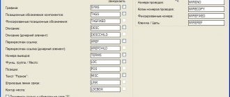
1 . 1 . This standard specifies the methods used to distinguish terminals and the general rules for their uniform designation.
Note: The term “terminal designation” is used to designate conductive sections of the circuit and electrical elements intended for connection.
1 . 2. A unified designation method can be used when using computer technology and transmitting information by teletype.
1 . 3. The drawings in this standard are provided as examples to clarify the text.
The distinctive features of the method indicated and I are:
1) arrangement of clamps according to the chosen system;
2) conventional color according to the chosen system;
3) conventional graphic designation according to GOST 2.721;
4) alphanumeric designation according to section. 4.
Note: The indicated methods are equally valuable from the point of view of their use.
It is allowed to use graphic symbols in accordance with GOST 2.721 instead of alphanumeric symbols (see Tables 1 and 2).
2. 2. The choice of designation method depends on the type of device, the location of the terminals, and the complexity of the device or wiring.
2. 3. Alphanumeric symbols are used for complex devices and wiring and are convenient for transmission by teletype.
3. 1 . To designate the terminals of electrical elements, a conventional color and corresponding graphic or alphanumeric designation are used.
3. 2. When designating clamps with a conventional color, the relationship between the color and the equivalent graphic or alphanumeric designation must be shown in the accompanying documentation.
3. 3. If the design of a particular element or device does not allow a clamp to be designated, then the accompanying documentation must show the relationship between the location of the clamp, equivalent graphical or alphanumeric symbols, as well as the relative positions of the clamps.
4 . 1 . When constructing letters e-no-ts and frov notations, capital letters of the Latin alphabet and Arabic numerals are used.
It is not recommended to use the letters I and O.
It is allowed to omit one or more groups if this does not lead to an error during connections.
To separate groups consisting only of numbers or letters, use a dot. If there is no need to distinguish subsequent groups, the point can be omitted. For example, the full designation 1 U 11 can be written as follows: 1. 11, if there is no need to indicate group U; if there is no need to distinguish subsequent groups, the period can be omitted: 111.
4 . 3. It is allowed to use the signs “+” and “-” when transmitting by teletype.
Regulations
Taking into account the large number of electrical elements, a number of normative documents have been developed for their alphanumeric (hereinafter referred to as BO) and conventional graphic designations (UGO) to eliminate discrepancies. Below is a table showing the main standards.
Table 1. Standards for graphic designation of individual elements in installation and circuit diagrams.
| GOST number | Short description |
| 2.710 81 | This document contains GOST requirements for BO of various types of electrical elements, including electrical appliances. |
| 2.747 68 | Requirements for the dimensions of displaying elements in graphical form. |
| 21.614 88 | Accepted codes for electrical and wiring plans. |
| 2.755 87 | Display of switching devices and contact connections on diagrams |
| 2.756 76 | Standards for sensing parts of electromechanical equipment. |
| 2.709 89 | This standard regulates the standards in accordance with which contact connections and wires are indicated on diagrams. |
| 21.404 85 | Schematic symbols for equipment used in automation systems |
It should be taken into account that the element base changes over time, and accordingly changes are made to regulatory documents, although this process is more inert. Let's give a simple example: RCDs and automatic circuit breakers have been widely used in Russia for more than a decade, but there is still no single standard according to GOST 2.755-87 for these devices, unlike circuit breakers. It is quite possible that this issue will be resolved in the near future. To keep abreast of such innovations, professionals monitor changes in regulatory documents; amateurs do not have to do this; it is enough to know the decoding of the main symbols.
Types of electrical circuits
In accordance with ESKD standards, diagrams mean graphic documents on which, using accepted notations, the main elements or components of a structure, as well as the connections connecting them, are displayed. According to the accepted classification, there are ten types of circuits, of which three are most often used in electrical engineering:
- Functional, it shows the node elements (depicted as rectangles), as well as the communication lines connecting them. A characteristic feature of this scheme is minimal detail. To describe the main functions of nodes, the rectangles displaying them are signed with standard letter designations. These can be various parts of the product that differ in functionality, for example, an automatic dimmer with a photo relay as a sensor or a regular TV. An example of such a scheme is presented below.
Example of a functional diagram of a television receiver - Fundamental. This type of graphic document displays in detail both the elements used in the design and their connections and contacts. The electrical parameters of some elements can be displayed directly in the document, or presented separately in the form of a table.
Example of a circuit diagram of a milling machine
If the diagram shows only the power part of the installation, then it is called single-line; if all elements are shown, then it is called complete.
Single Line Diagram Example
- Electrical wiring diagrams. These documents use positional designations of elements, that is, their location on the board, method and order of installation are indicated.
Installation diagram of a stationary flammable gas detector
Read also: Replacing the primer on a chainsaw
If the drawing shows the wiring of the apartment, then the locations of lighting fixtures, sockets and other equipment are indicated on the plan. Sometimes you can hear such a document called a power supply diagram; this is incorrect, since the latter shows how consumers are connected to a substation or other power source.
Having dealt with the electrical circuits, we can move on to the designations of the elements indicated on them.
General provisions
The marking (designation) of secondary circuits serves to identify them in the electrical circuit. Circuit markings are carried out on diagrams and at the ends of physical conductors connected to product terminals. It is performed in Arabic numerals, and in some cases with a letter prefix made from capital letters of the Latin alphabet.
Sections of circuits are designated regardless of the symbols of the terminals of the devices to which the circuit conductors are connected. Sections of circuits separated by device contacts, relay windings, resistors, capacitors and other elements are considered different, therefore they have different markings. Sections of circuits converging in one circuit node have the same markings, while the circuit marking does not change when passing through the clamps.
The complete circuit often includes individual complete devices that have factory-labeled circuits. In these cases, in order to harmonize the marking adopted in the complete scheme with the factory marking, the factory marking is indicated in brackets near the main marking.
With the horizontal method of depicting circuits in the diagram, markings are placed above the image of the circuits, and the numbers of the device terminals are placed under the image of the circuits. Branching sections of the circuit are marked sequentially from the power source (circuit breaker, fuses) from left to right in the direction from top to bottom.
With the vertical method of depicting circuits in the diagram, the markings are placed to the left of the circuit image, and the terminal numbers are to the right; the branching sections of the chain are marked from top to bottom in the direction from left to right.
All secondary circuits of one installation unit (for example, switches of a three-winding transformer) must have different designations. The designations of circuits of similar installation groups are usually performed in the same way. If in the diagram there are sections of circuits of different mounting units with the same markings, then to distinguish them, the markings are supplemented with an index characterizing the chain’s belonging to a specific mounting unit. The distinctive index is placed in front of the circuit designation and separated from it by a dividing line. This index can be the number of the installation unit or the number of the circuit element (for example, 1 - 205, 2 - 205, 3 - 205)
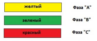
AC circuit markings
Performed with consecutive numbers, without dividing into even or odd, with the addition of a letter characterizing the phase (A, B, C) or neutral (0 or N) before the digital part:
– A1 – A99
– B1 – B99
– C1 – C99
– N1 – N 99
It is allowed to omit the letter index before the digital mark in cases where phase indication is not required (for example, control circuits on alternating operating current). In this case, the group of brands (A, B, C) 301 - 399 can be used for control circuits if this circuit does not provide for current circuits of differential busbar protection.
table 2
| Distribution of groups of numbers for marking AC control circuits | ||||
| Name of circuits | A group of numbers to designate circuits within one installation unit | |||
| Basic group of numbers | (A, B, C) 1-99 | (A, B, C) 101 - 199 | (A, B, C) 201 - 299 | (A, B, C) 301 - 399* |
| Control circuits | (A, B, C) 3-49 | (A, B, C) 103 - 149 | (A, B, C) 203 - 249 | (A, B, C) 303 - 349 |
| Switching circuit | (A, B, C) 3 | (A, B, C) 103 | (A, B, C) 203 | (A, B, C) 303 |
| Trip circuit | (A, B, C) 33 | (A, B, C) 133 | (A, B, C) 233 | (A, B, C) 333 |
| Automation circuits | (A, B, C) 50 - 69 | (A, B, C) 150- 169 | (A, B, C) 250- 269 | (A, B, C) 350 - 369 |
| Circuits of lamps signaling the position of switches | (A, B, C) 70 - 79 | (A, B, C) 170- 179 | (A, B, C) 270 - 279 | (A, B, C) 370 - 379 |
| Remote control command latching relay circuits | (A, B, C) 80 - 89 | (A, B, C) 180- 189 | (A, B, C) 280 - 289 | (A, B, C) 380- 389 |
| Emergency shutdown and open circuit signal circuits | (A, B, C) 90-99 | (A, B, C) 190- 199 | (A, B, C) 290 - 299 | A, B, C) 390 - 399 |
| Alarm buses | (A, B, C, N) 700 - 709 | |||
| Individual warning circuits | (A, B, C, N) 900 - 999 | |||
| * Group of brands (A, B, C) 301 - 399 can be used for control circuits if this circuit does not provide current circuits for differential busbar protection. | ||||
Tire markings
Bus bars from which secondary circuits for various purposes extend: operational circuits, alarm circuits, voltage circuits, etc. have a special marking system. The alphabetic and numerical markings of tires and their purpose are given in the table:
Table 3
| Letter marking | Digital marking | Purpose of tires | ||
| old | new | |||
| + ShP | + EY | Power buses for switches turning on electromagnets | ||
| – ShP | – E.Y. | |||
| + SHU | +EC | – | DC power supply buses for control circuits | With one control system |
| – SHU | – E.C. | – | ||
| + 1SHU | +EC1 | – | With two control systems | |
| + 2SHU | +EC2 | – | ||
| – 1SHU | – EC1 | – | ||
| – 2SHU | – EC2 | – | ||
| 1SHU | EC1 | Power supply buses for control circuits using alternating operating current | ||
| 2SHU | EC2 | |||
| (+) ShM | (+)EP | 100 | Blinking bar for switch position lamps | |
| Å SHU | Å EC | 200 | “Dark” plus alarm when the alarm lamps are powered from the control buses | |
| + ShS | +EH | 701 | Power buses for common alarm circuits | |
| – ShS | – E.H. | 702 | ||
| + 1ShS | + EH1 | 701 | Power buses for 1 signaling section | |
| – 1ShS | – EH1 | 702 | ||
| + 2ShS | + EH2 | 701 | Power buses 2 alarm sections | |
| – 2ShS | – EH2 | 702 | ||
| Å ShS | Å EC | 703 | “Dark” plus alarm when alarm lamps are powered from alarm buses | |
| ShZA | E.H.A. | 707 (705) | Sound alarm bus | |
| 1SHZP | EHP1 | 709 | Sound warning alarm bars | No time delay |
| 2ШЗП | EHP2 | 711 | With time delay | |
| SHTB | 716 | Tire of the sign “Pointer not raised” | ||
| ShSM | EHD | 801 | Alarm lamp flashing bar | |
| ShPL | EHL | 704 | Bus for checking the serviceability of indicator lamps | |
| 1ShBR | 1601 | Disconnector blocking bars | ||
| 2ShBR | 1602 | |||
| SHNA | EV1A | Voltage bars | 1 ssh | |
| EV2A | 2 SSH | |||
| SHNV | EVB | |||
| SHNS | E.V.C. | |||
| ШН0 | EVN | |||
| SHNN | ||||
| ShNK | ||||
| SHNI | ||||
| SHNF | ||||
| EVap | Voltage bars for meters | |||
| EVBp | ||||
| EVCp | ||||
| EVNp | ||||
| + SHST | + UNT | 811 | Power supply buses for process alarms | |
| — SHST | -ENT | 812 | ||
| CMT | EPT | 800 | The “blinking” bar of the process alarm panel | |
| SHSMT | EPDT | 804 | The “blinking pick-up” bar of the process alarm panel | |
| Sound technological alarm buses: | ||||
| 1SHZT | ENRT1 | 813 | instant action | |
| (2SHZT) | ENRT2 | 815 | with time delay | |
| 1 SHACHR | EPF1 | 801 | Automatic frequency unloading busbars | |
| 2SHACHR | EPF2 | 803 | ||
| — 1SHAZ | -EAF1 | Tire (negative) of the AFR device | ||
| — 2SHAZ | -EAF2 | |||
| 1VShS | EHB1 | Emergency shutdown signal blocking bus during AFC operation | ||
| 2VShS | EHB2 | |||
| 1ШРЧ | EPF1 | 717 | Frequency control pulse bars during synchronization | |
| 2ШРЧ | EPF2 | 718 | ||
| 1ShRS | EST1 | 719 | Buses of automatic synchronizer advance time settings | |
| 2ShRS | EST2 | 723 | ||
| 3ShRS | EST3 | 725 | ||
| 1SHIS | ECS1 | 721 | Switching pulse bars during synchronization | |
| 2SHIS | ECS2 | 722 | ||
| SHSH | ESS | — | Power supply and intermediate buses of synchronization circuits | |
| Vsha | EA.A | A790 | Auxiliary buses for synchronization | |
| VShs | EA.S | S790 | ||
| SHSHa | ES1.A | A610 | Voltage bars for synchronization | |
| ШСХb | ES1.B | B610 | ||
| ШСХc | ES1.B | C6I0 | ||
| SHSHa | ES2.A | A620 | ||
| ШСХb | ES2.B | B620 | ||
| SHSHs | ES2. WITH | S620 | ||
| ШСХd | ES1.B | A780 | ||
| 1ШHa | EV1.A | Depending | Voltage bars | |
| 1SHHv | EV1.B | |||
| 1ШНс | EV1.C | |||
| 1ShHo | EV1.N | |||
| 1SHn | EV1.H | from bus voltage | ||
| 1ShNi | EV1.U | |||
| 1ShHk | EV1.K | |||
| 1ShHf | EV1.G | |||
| +ShB | +EB | 880 | Busbars for operational blocking of disconnectors | |
| -SHB | -EV | |||
| SBR | EBQ | |||
| SHOP | EYQG | — | Provided food bus | |
| SHZ | E.G. | — | Ground fault bus | |
| SHO | EEL | — | Lighting bar | |
| SHO | EC | — | Heating bar | |
| 1ShMN | EVMI | 11 | Minimum voltage protection busbars of the LV RU section | |
| 2ShMN | EVM2 | 13 | ||
| SHNV1 | EVC1 | — | Voltage circuit bars of the ZZP-1 device | |
| SHNV2 | EVC2 | — | ||
| ESS1 | DC buses of synchronization devices | |||
| ESS2 | ||||
| ECS1 | ||||
| ECS2 | ||||
| +ED | Arc protection bars | |||
| ED1 | ||||
| ED2 | ||||
| +EQC | Switchgear level bars 6 – 10 kV. | |||
| EQCT1 | ||||
| EQCT2 | ||||
| +EWB | Logical protection buses | |||
| EWBT1 | ||||
| EWBT2 | ||||
Notes:
1. Area alarm buses are marked with the same letter code with the addition of the alarm area number after the letter code, and a number characterizing the area number is added before the digital main mark.
2. EPFI synchronization buses. EPF2, EST1. EST2 and FST3 are for power plants only.
General provisions.
The rows of terminals carry the circuits necessary for connecting the cores of control cables and interconnections, test instruments, as well as circuits that must be switched at the terminals during operation without disconnecting the wires and cores of the control cables or can provide unification of the product.
When the clamps are placed vertically, they are placed in one row on the left side of the panel, and if there are two mounting units, they are placed on different sides of the panel. The numbering of the clamps for each installation unit within one panel is carried out end-to-end, starting from No. 1, from top to bottom when the clamps are arranged vertically, and from left to right when the clamps are arranged horizontally.
Types of clamps.
Typically typesetting is used; clamps that make it possible to remove any of them without disassembling the entire row. At the beginning and end of the row of clamps, marking blocks are installed to ensure fixation of the assembled row of clamps on the rail. Marking blocks are also used for applying inscriptions (numbers and names of the installation unit or the functional purpose of the circuits). Marking pads are not numbered.
There are three types of clamps: normal, connecting and test. Normal clamps are used to connect two ends of wires or cables, connecting clamps are used to combine three or more circuits of the same name into a common point, test clamps are used for current circuits (to ensure the ability to remove any device or connect a control and testing device without breaking the circuit), for ease of use (in voltage circuits, in wiring circuits of operational “plus” and “minus”, in on and off circuits going directly to the switch drive), to connect signaling circuits to common buses (to ensure the possibility of sequentially disconnecting circuits when searching for “ground”) , in the output circuits of relay protection and automation devices (if pads or switches are not provided), in circuits going directly to the remote alarm panel or automated control system.
Since the test and normal (connecting) clamps have different height dimensions, a special 3 mm wide dividing block is installed between the test and the next normal (connecting) clamp.
Picture 1
Illustration of different types of clamps in rows of panel clamps:
a - for the left side; b - for the right side; 1 — marking block; 2—test clamps; 3—normal clamps; 4— connecting clamps; 5 — end marking block; b - connecting the clamps with brackets from the outside; A - K - fields for inscriptions
Fields A - K are intended for making inscriptions: A - for the name of the installation unit (for example, “Transformer 110/10 kV”), B - for the panel number of the installation unit (a number of clamps, for example 02), C - for the brand of the installation unit (for example , 2T), G - for the address of the wire to the device (positional number of the device, for example SG1), D - for the address of the wire from the device to a row of terminals (for example, X2:1), E - for the serial number of the terminal (for example, 2), Ж - for the address of the cable core (for example, X2:1), L" - for marking the circuit according to the complete circuit (for example, A411).
In the address of the wire to the device, the device terminal number is often added to the position number of the device, separated by a colon. If all devices installed on the panel belong to one mounting unit, then in fields D and G the panel number of the mounting unit (a row of clamps) is not indicated, while the addresses of the wire from the device to the row of clamps and the cable core are left with the letter X, a colon and the number of the clamp .
The relay panel consists of blocks, and the equipment of one mounting unit is placed on the block, then the panel number of the row is entered in the address of the cable core (conductor jumper), and the address of the wire from the device consists of the letter X, a colon and the number of the block terminal. If the block contains the equipment of two or more installation units, then the block and panel numbers of the row of clamps (through a dot) are entered in the address of the cable core (conductor jumper), and only the block number of the row is entered in the address of the wire. In this case, in field B indicate the panel number of the installation unit (a row of clamps), and through the fraction - the block number of the row of clamps.
A - devices, blocks
| Complete devices (panels, consoles, cabinets, drawers) | A | |||||
| Amplifiers | A | |||||
| Regulators | AA | |||||
| Current regulators | AA | |||||
| Frequency regulators | A.F. | |||||
| Voltage and excitation regulators | AV | |||||
| Power regulators | A.W. | |||||
| Actuator drives | AB | |||||
| Functional modules (including cassette) | AE | |||||
| Relay block, protection kit (short circuit type, short circuit type, against ground faults) | A.K. | |||||
| Oscilloscope trigger | AKG | |||||
| Locking device type KRB | AKV | |||||
| Automatic reclosing device (ARD) | AKS | |||||
| Line longitudinal differential protection kit | AKW | |||||
| Resistance relay kit | AKZ | |||||
| RF transceiver | AV | |||||
| B - converters | ||||||
| Speaker | VA | |||||
| Telephone (capsule) | B.F. | |||||
| temperature sensor | VC | |||||
| Photocell | B.L. | |||||
| Microphone | VM | |||||
| Pickup | B.S. | |||||
| Selsyn, sensor | B.G. | |||||
| Pressure meter | B.P. | |||||
| Speed sensor (tachometer) | BR | |||||
| Reactive volt-amp-hour meter | BVA | |||||
| Watt hour meter | B.W. | |||||
| C - capacitors | ||||||
| Capacitor power batteries | NE | |||||
| Capacitor charging units | C.G. | |||||
| E - elements are different | ||||||
| Reacting element (null indicator) | EA | |||||
| A heating element | EC | |||||
| Lighting lamp | EL | |||||
| L - inductive coils | ||||||
| Choke, coupling choke, arc suppression coil | L | |||||
| Reactor | LR | |||||
| Generator field winding | LG | |||||
| Exciter field winding | L.E. | |||||
| Motor field winding | L.M. | |||||
| M - motors (asynchronous and synchronous) | M | |||||
| R - resistors | ||||||
| Resistors are constant and variable | R | |||||
| Measuring shunt | R.S. | |||||
| Potentiometer | R.P. | |||||
| Rheostat | R.R. | |||||
| Thermistor | RK | |||||
| Varistor | RU | |||||
| General provisions The marking (designation) of secondary circuits serves to identify them in the electrical circuit. Circuit markings are carried out on diagrams and at the ends of physical conductors connected to product terminals. It is performed in Arabic numerals, and in some cases with a letter prefix made from capital letters of the Latin alphabet. Sections of circuits are designated regardless of the symbols of the terminals of the devices to which the circuit conductors are connected. Sections of circuits separated by device contacts, relay windings, resistors, capacitors and other elements are considered different, therefore they have different markings. Sections of circuits converging in one circuit node have the same markings, while the circuit marking does not change when passing through the clamps. The complete circuit often includes individual complete devices that have factory-labeled circuits. In these cases, in order to harmonize the marking adopted in the complete scheme with the factory marking, the factory marking is indicated in brackets near the main marking. With the horizontal method of depicting circuits in the diagram, markings are placed above the image of the circuits, and the numbers of the device terminals are placed under the image of the circuits. Branching sections of the circuit are marked sequentially from the power source (circuit breaker, fuses) from left to right in the direction from top to bottom. With the vertical method of depicting circuits in the diagram, the markings are placed to the left of the circuit image, and the terminal numbers are to the right; the branching sections of the chain are marked from top to bottom in the direction from left to right. All secondary circuits of one installation unit (for example, switches of a three-winding transformer) must have different designations. The designations of circuits of similar installation groups are usually performed in the same way. If in the diagram there are sections of circuits of different mounting units with the same markings, then to distinguish them, the markings are supplemented with an index characterizing the chain’s belonging to a specific mounting unit. The distinctive index is placed in front of the circuit designation and separated from it by a dividing line. This index can be the number of the installation unit or the number of the circuit element (for example, 1 - 205, 2 - 205, 3 - 205) Marking of operational DC circuits As a rule, it is produced with digital stamps taking into account their polarity. Sections of circuits with positive polarity are marked with odd numbers, and sections of negative polarity with even numbers. Sections of circuits that change their polarity during operation, as well as those that do not have a clearly defined polarity (circuits connecting series-connected relay windings, resistances, capacitors, etc.), can be marked with any numbers - even or odd. The numbers allocated to designate operational circuits, control and protection circuits are divided into hundreds in each group (one group of numbers from 1 to 99, another from 101 to 199, etc.). So, for example, an autotransformer with separate power supply for protection circuits V-220 and V-110 may have the following circuit markings: - 1 - 99 - protection — 101 – 199 – control circuits V-220 — 201 – 299 – control circuits B-110 In the case when the main numbering is not enough (there are more than 99 circuits in any group), additional four-digit marking is used with the addition of a number in front of the main numbering: — 101 – 199; — 1101 – 1199; — 2101 – 2199; — 3101 – 3199; etc. Many circuits have reserved or traditionally used markings: – 1 – “+” power supply — 2 — “–” power supply – 3 – 19 – inclusions (main marking – 3) — 20 – 29 – circuits of relay-repeater coils of bus disconnectors – 30 – 49 – shutdowns In this case, the circuit coming directly from the control key or relay contact is marked 33, after the anti-jump relay coil - 37, between the switch block contact and the shutdown solenoid - 39. 50 – 69 – circuits of automatic reclosure, automatic transfer and other automation The automatic reclosing prohibition circuit during operation of the breaker failure protection device or the sensitive element of the automatic reclosure protection device (unconditional automatic reclosing prohibition) is, as a rule, marked 67; prohibition of automatic reclosing during operation of the automatic recloser (operational prohibition of automatic reclosing) – 65 70 – 79 – switch position signaling lamp circuits If the contacts supplying a signal to the lamp are on the “+” side, the green lamp circuit is marked 73, the red lamp circuit is marked 75. 80 – 89 – relay coil circuits for fixing remote control commands 90 – 99 – emergency shutdown audible alarm circuits The number 100 is used to mark the flashing light circuit. In the case when the main numbering is not enough (there are more than 99 circuits in any group), additional four-digit marking is used with the addition of a number in front of the main numbering: — 101 – 199; — 1101 – 1199; — 2101 – 2199; — 3101 – 3199; etc. Sometimes the number is preceded by a letter characterizing the functional purpose of the circuit. For example, breaker failure circuits are marked in the format P*** (P1, P12, P139, etc.) or AR***. Apparently, because breaker failure circuits can be found in the circuits of most connections, and the responsibility of these circuits is very high. Telemechanics circuits are designated by the letter T (T1 – T99), communication circuits by U (U1 – U99). Circuits of electromagnets for turning on switches are marked with numbers 871 – 874, additional markings – 875 – 899. Individual circuits of warning and process signals are marked 901 - 999. These include, for example, circuits from an external contact (gas protection signal element, etc.) to an indicator relay or to a central alarm panel. Table 1 | 1-99 | 101 — 199 | 201 — 299 | 301 — 399 | 401 -499 | |
| Additional | 1101 - 1199 2101 -2199, etc. | 1201 - 1299 2201 - 2229, etc. | 1301 - 1399 2301 - 2399, etc. | 1401 - 1499 2401 - 2499, etc. | ||
| Control, automation and alarm circuits: | ||||||
| "+" power supply | 1 | 101 | 201 | 301 | 401 | |
| "-" power supply | 2 | 102 | 202 | 302 | 402 | |
| commands to drive the switch: | ||||||
| turn on | 3 | 103 | 203 | 303 | 403 | |
| disable | 33 | 133 | 233 | 333 | 433 | |
| inclusion | 3-19 | 103-119 | 203 — 219 | 303 — 319 | 403 -419 | |
| relay windings RPO (KQT) | 5 | 105 | 205 | 305 | 405 | |
| shutdowns | 30-49 | 130- 149 | 230 — 249 | 330 — 349 | 430 — 449 | |
| relay windings RPV (KQC) | 35 | 135 | 235 | 335 | 435 | |
| relay windings - repeaters of bus disconnectors | 20-29 | 120- 129 | 220 — 229 | 320 — 329 | 420 — 429 | |
| AR, AVR and other automation devices | 50-69 | 150-169 | 250 — 269 | 350 — 369 | 450-469 | |
| switch position signaling lamps | 70-79 | 170-179 | 270 — 279 | 370 — 379 | 470-479 | |
| windings of command fixation relays or repeater fixation relays of auxiliary contacts of switches | 80-89 | 180-189 | 280 — 289 | 380 — 389 | 480-489 | |
| audible emergency shutdown alarm | 90-99 | 190-199 | 290 — 299 | 390 — 399 | 490-499 | |
| Excitation circuits | 600-699 | |||||
| Circuits of central signaling and synchronization devices | 700-799 (1700-1799, 2700-2799, etc.) | |||||
| Reserve groups of numbers | 850 -870 (1850-1870,2850-2870, etc.) | |||||
| Switch activation electromagnet circuits | 871-874 | |||||
| Reserve groups of numbers | 875-899 (1875-1899,2875-2899, etc.) | |||||
| Individual signal circuits | 901-999(1901-999.2901-2999, etc.) | |||||
| Disconnector interlock circuits | 600-1699 (2600-2699,3600-3699, etc.) | |||||
Date: 2019-07-30, .
1Next ⇒
The materials presented on the site are solely for informational purposes to Internet users and do not pursue commercial purposes or copyright infringement. © 2022 — 2022
Graphic symbols
Each type of graphic document has its own designations, regulated by relevant regulatory documents. Let us give as an example the basic graphic symbols for different types of electrical circuits.
Examples of UGO in functional diagrams
Below is a picture depicting the main components of automation systems.
Examples of symbols for electrical appliances and automation equipment in accordance with GOST 21.404-85
Description of symbols:
- A – Basic (1) and acceptable (2) images of devices that are installed outside the electrical panel or junction box.
- B - The same as point A, except that the elements are located on the remote control or electrical panel.
- C – Display of actuators (AM).
- D – Influence of MI on the regulating body (hereinafter referred to as RO) when the power is turned off:
- RO opening occurs
- Closing RO
- The position of the RO remains unchanged.
- E – IM, on which a manual drive is additionally installed. This symbol may be used for any RO provisions specified in paragraph D.
- F- Accepted mappings of communication lines:
- General.
- There is no connection at the intersection.
- The presence of a connection at the intersection.
UGO in single-line and complete electrical circuits
There are several groups of symbols for these schemes; we present the most common of them. To obtain complete information, you must refer to the regulatory documents; the numbers of state standards will be given for each group.
Power supplies.
To designate them, the symbols shown in the figure below are used.
UGO power supplies on schematic diagrams (GOST 2.742-68 and GOST 2.750.68)
Description of symbols:
- A is a constant voltage source, its polarity is indicated by the symbols “+” and “-”.
- B – electricity icon indicating alternating voltage.
- C is a symbol of alternating and direct voltage, used in cases where the device can be powered from any of these sources.
- D – Display of battery or galvanic power supply.
- E- Symbol of a battery consisting of several batteries.
Communication lines
The basic elements of electrical connectors are presented below.
Designation of communication lines on circuit diagrams (GOST 2.721-74 and GOST 2.751.73)
Description of symbols:
- A – General display adopted for various types of electrical connections.
- B – Current-carrying or grounding bus.
- C – Designation of shielding, can be electrostatic (marked with the symbol “E”) or electromagnetic (“M”).
- D – Grounding symbol.
- E – Electrical connection with the device body.
- F - On complex diagrams, consisting of several components, a broken connection is thus indicated; in such cases, “X” is information about where the line will be continued (as a rule, the element number is indicated).
- G – Intersection with no connection.
- H – Joint at intersection.
- I – Branches.
Designations of electromechanical devices and contact connections
Examples of the designation of magnetic starters, relays, as well as contacts of communication devices can be seen below.
UGO adopted for electromechanical devices and contactors (GOSTs 2.756-76, 2.755-74, 2.755-87)
Description of symbols:
- A – symbol of the coil of an electromechanical device (relay, magnetic starter, etc.).
- B – UGO of the receiving part of the electrothermal protection.
- C – display of the coil of a device with mechanical interlock.
- D – contacts of switching devices:
- Closing.
- Disconnecting.
- Switching.
- E – Symbol for designating manual switches (buttons).
- F – Group switch (switch).
UGO of electric machines
Let us give several examples of displaying electrical machines (hereinafter referred to as EM) in accordance with the current standard.
Designation of electric motors and generators on circuit diagrams (GOST 2.722-68)
Description of symbols:
- A – three-phase EM:
- Asynchronous (squirrel-cage rotor).
- The same as point 1, only in a two-speed version.
- Asynchronous electric motors with phase-phase rotor design.
- Synchronous motors and generators.
- B – Collector, DC powered:
- EM with permanent magnet excitation.
- EM with excitation coil.
Designation of electric motors on diagrams
UGO transformers and chokes
Examples of graphic symbols for these devices can be found in the figure below.
Correct designations of transformers, inductors and chokes (GOST 2.723-78)
Description of symbols:
- A – This graphic symbol can indicate inductors or windings of transformers.
- B – Choke, which has a ferrimagnetic core (magnetic core).
- C – Display of a two-coil transformer.
- D – Device with three coils.
- E - Autotransformer symbol.
- F – Graphic display of CT (current transformer).
Designation of measuring instruments and radio components
A brief overview of the UGO of these electronic components is shown below. For those who want to become more familiar with this information, we recommend viewing GOSTs 2.729 68 and 2.730 73.
Examples of graphic symbols for electronic components and measuring instruments
Description of symbols:
- Electricity meter.
- Picture of an ammeter.
- Device for measuring network voltage.
- Thermal sensor.
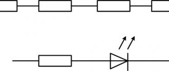
- Fixed value resistor.
- Variable resistor.
- Capacitor (general designation).
- Electrolytic capacity.
- Diode designation.
- Light-emitting diode.
- Image of a diode optocoupler.
- UGO transistor (in this case npn).
- Fuse designation.
UGO lighting devices
Let's look at how electric lamps are displayed on a circuit diagram.
An example of how light bulbs are indicated on diagrams (GOST 2.732-68)
Description of symbols:
- A – General image of incandescent lamps (LN).
- B – LN as a signaling device.
- C – Typical designation of gas-discharge lamps.
- D – High-pressure gas-discharge light source (the figure shows an example of a design with two electrodes)
Designation of elements in the electrical wiring diagram
Concluding the topic of graphic symbols, we give examples of displaying sockets and switches.
An example of an image on the wiring diagrams of flush-mounted sockets
How sockets of other types are depicted is easy to find in the regulatory documents that are available on the Internet.
Designation of flush-mounted switches
Designation of sockets and switches
Installation of electrical installations - Marking circuits in electrical diagrams
Page 2 of 83
The letter symbols of the elements included in the circuit, according to GOST 2.710-81, must be written in Latin letters (Fig. 1.1). This decision was made in connection with the constant expansion of international relations in the field of design, installation and operation of electrical installations.
Rice. 1.1. Marking of power circuits in circuits (GOST 2.710-81): a - alternating current; 6 - direct current To identify conductors, determine their purpose and the position of individual sections of the circuit in electrical circuits, markings are used. Sections of the circuit separated by device contacts, relay windings, instruments, machines and other elements receive different markings. Sections of the circuit passing through detachable, detachable or non-demountable contact connections, as a rule, receive the same markings. If necessary, for such sections of the circuit it is allowed to add serial numbers or designations of devices (units) to the marking, separating them with a hyphen, and for sections of the circuit passing through detachable
Rice. 1 2 Marking of control, protection, measurement circuits (GOST 2 710-81): a - direct current; b - alternating current (current transformer circuits) contact connections, assign different markings. The circuits in the diagrams are marked regardless of the numbering of the input and output terminals of machines, devices, instruments, and relays. The sequence of circuit markings is taken from the input of the power source to the consumer, and the branching sections of the circuit are marked on the diagrams from top to bottom and from left to right. Arabic numbers and capital letters are used for marking. Numbers and letters are written in the same size. When marking circuits, it is allowed to leave reserve numbers. AC power circuits are marked with letters indicating phases and sequential numbers. In three-phase AC circuits, the phases are marked: A, B, C and N, in two-phase circuits - A, B\B, C; C, L, and in single-phase - A, N; B, N; C, N (Fig. 1.1, a). In DC power circuits, sections of circuits with positive polarity are marked with odd numbers, and sections of negative polarity with even numbers (Fig. 1.1,6). The input and output sections of the circuit are marked with polarity: plus (+) and minus (-). The middle conductor is designated by the letter N or M. It is allowed to mark DC power circuits with sequential numbers. Control, protection, signaling and measurement circuits are marked with sequential numbers within the product and connection (Fig. 1.2,a). It is allowed to put down symbols before marking that characterize the functional purpose of the circuit. In Fig. 1.2, and the marking sequence is set from plus to minus (for example, the windings of an electric machine Ml are marked 4-5, contactor K2 is marked 6-7, etc.). The branches are marked from top to bottom.
- Back
- Forward