Electric cable marking.
The main principle of organizing electrical wiring and laying lines is the competent choice of cables and wires used. At this stage, the operating conditions of the product are taken into account, based on which a decision is made on the required cross-section, number of cores, type of sheath, insulation and other important parameters. Key data about the cable is encoded in its markings - a unique set of letters and numbers that is printed on the outside of the product or indicated on a special tag. The correct selection of products depends on how accurately the abbreviations and other designations are deciphered. Errors made at this stage can cause the cable to overheat during direct operation, and will also lead to a short circuit and even a fire.
Power cable marking.
The choice of suitable wires and cables is largely determined by the specific installation conditions. For example, for those products that will be installed outdoors, it is better to give preference to a rubber shell, and for indoor work, a PVC shell and insulation is suitable. To simplify the selection of the optimal product, Russian GOST 18690-2012 obliges manufacturers to apply a symbol to their products. Cable marking allows you to quickly determine the following significant parameters:
- number of cores;
- section;
- the material from which the structural elements are made.
The electrical cable can be single or multi-core. Copper is most often used as a conductor, but in some cases aluminum is also used. It is cheaper, but is inferior in conductive capacity by no more than 20%, which is easily compensated by an increase in cross-sectional area. The last parameter allows you to determine the level of internal resistance.
If you plan to lay a power cable in a group or it will be used in public buildings, you should pay special attention to insulation and sheath materials, which should have low levels of gas and smoke emission. Equally important is the presence of an aluminum screen. Information about all these parameters can be obtained from the labeling, the decoding of which should be entrusted to a specialist if you do not have your own experience working with similar products.
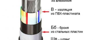
CABLE CONSTRUCTION
- The conductor is multi-wire tinned copper 4 (for 0.35 and 0.5 mm kV) or class 3 flexibility according to GOST 22483. It is possible to manufacture conductors from untinned copper wires.
- Insulation - from PVC plastic compound of reduced fire hazard, or a polymer composition that does not contain halogens
- Twisting is possible either in pairs (the letter “V” after the letter “Sh”; example - MKShVng(A)-HF), or general.
- Waist insulation – polyethylene terephthalate tape. It is possible to produce unshielded cables without film.
- The common screen is a braid of copper wires. By agreement with the consumer, it is possible to manufacture a common screen in the form of a braid of tinned copper wires. Available with alumina screen.
- The inner shell is made of PVC plastic compound of reduced fire hazard or a polymer composition that does not contain halogens.
- The armor is woven from galvanized steel wires.
- The outer shell is made of PVC plastic with reduced fire hazard or from polymer compositions that do not contain halogens.
Power cable marking system.
The letters and numbers indicated on the product will help you quickly understand what type of product is in front of you. To decipher, it is necessary to take into account not only the symbolic designations of certain characteristics, but also their position. According to accepted standards, power cable marking is based on the principle indicated in the table below.
| Location | Encoding | Characteristic |
| 1st position | Letter | Core material |
| 2nd position | Letter | Insulation material |
| 3rd position | Letter | Type of containment (if available) |
| 4th position | Letter | Armor type (if available) |
| 5th position | Letter | Characteristics of outer cover, cable structure |
| 6th position | Digital | Number of conductors |
| 7th position | Digital | Core cross-sectional area |
| 8th position | Alphanumeric | Climatic conditions for operation |
| 9th position | Alphanumeric | Indication of GOST or TU |
In order to quickly find the right brand when viewing a cable catalog, it is important to remember not only the decoding of the alphanumeric designations, but also the type of characteristics reflected on each individual position.
Cable catalog.
Depending on the design features of the conductive product, its symbol may not contain all parameters. So for an aluminum electrical cable, the marking begins with the letter A. If it is not in the first position, this means that this is a product with conductive copper cores. The following letters indicate what the insulation is made of. This term refers to the protective covering of conductors, which is necessary to prevent them from shorting with each other. The insulation material is designated by the abbreviations V, P, Pv, Ps, R, NR, F, C, K, KG. The following letters will tell you the type of inner containment used. It is laid on insulated cores and provides higher cable resistance to water, mechanical damage, and extreme temperatures. The internal protective shell is designated by the letters A, C, P, Pu, B or P, but is not present in all products. Therefore, if there is a blank in the 3rd position, this means that this structural element is not included in the product. An equally optional element is armor, the type of which is indicated on the 4th position of the marking with the abbreviations BS, BbG, Bb, Bl, Bn, K, D, P. The armor is made of steel tapes or wire braiding and is needed to increase the mechanical strength of those wires and cables that bear increased load. Most often, protection is provided by a simple outer shell. It is made of dielectrics: fluoroplastic, polyethylene, PVC or rubber. The specific material is indicated by the letters V, Shv, Shp, Shps, N on the 5th position of the power cable marking. The letters O, E, G may also appear here, which indicate the design features of the product.
If we consider the digital markings that occupy the 6th and 7th positions, then they are always present. In some cases, numbers may be included to indicate the level of permissible operating voltage. If this is not the case, it means that the cable is designed for a 220 V network. Climatic zones of operation may not be indicated (they are used only on special-purpose products) and the number of GOSTs and TUs used.
APPLICATION AREA
The cables are intended for connection to stationary electrical appliances, devices, devices with a rated alternating voltage of up to 500 V, alternating current frequency up to 400 Hz or direct voltage up to 750 V. The cables can be laid in rooms, channels, tunnels.
The cable can be laid in explosive zones of classes 0,1 and 2 (according to GOST R IEC08) if there is no danger of mechanical damage to the cables. Fire hazard classes in accordance with GOST 31565-2012 are indicated in the fire certificate.
- P1b.8.2.2.2 - MKShVng(A)-LS, MKKShVng(A)-LS, MKEShVng(A)-LS, MKEKShVng(A)-LS;
- P1b.1.2.2.2 - MKShVng(A)-FRLS, MKKShVng(A)-FRLS, MKEShVng(A)-FRLS, MKEKShVng(A)-FRLS;
- P1b.8.1.2.1—MKShVng(A)-HF,MKKShVng(A)-HF, MKEShVng(A)-HF, MKEKShVng(A)-HF;
- P1b.1.1.2.1 - MKShVng(A)-FRHF, MKKShVng(A)-FRHF, MKEShVng(A)-FRHF, MKEKShVng(A)-FRHF.
Alphanumeric marking of power cables.
Having figured out the sequence in which cable characteristics are marked, you can begin to directly decipher them. Currently, there are more than 300 product brands that have their own coded designation. The table below will help you understand the most common lettering instructions that are used to describe product properties.
| Abbreviation | Possible position in marking | Decoding |
| A | 1, 3 | Aluminum |
| AA | 1 | Aluminum core and aluminum sheath |
| AC | 1 | Aluminum conductors and lead sheath |
| IN | 2, 3, 5 | Vinyl (PVC) |
| P | 2 | Polyethylene |
| Ps | 2 | Self-extinguishing polyethylene |
| Pv | 2 | Vulcanized (cross-linked) polyethylene |
| R | 2, 3 | Rubber |
| HP | 2 | Non-flammable rubber |
| F | 2 | Fluoroplastic |
| C | 2 | Film insulation |
| TO | 2 | Cable purpose: control |
| Kg | 2 | Flexible cable |
| WITH | 3 | Lead |
| P | 3 | Polyethylene hose |
| Pu | 3 | Reinforced polyethylene hose |
| B | 4 | Armor made of galvanized steel strips |
| BS | 4 | Lead armor |
| BbG | 4 | Armor made of steel profiled tape |
| BB | 4 | Two steel bands |
| Bl | 4 | Two steel belts with a plastic belt cushion |
| Bn | 4 | Steel tapes with non-flammable winding |
| TO | 4 | Steel wire armor with steel tape protection |
| D | 4 | Braided from two steel wires |
| P | 4 | Flat steel wire armor |
| G | 5 | The design provides protection against corrosion |
| E | 5 | Aluminum foil screen |
| ABOUT | 5 | Insulated conductors are connected by a winding |
| IN | 5 (if the last letter in the marking) | Paper outer insulation |
| Shv | 5 | Vinyl hose |
| Shp | 5 | Polyethylene hose |
| Shps | 5 | Self-extinguishing polyethylene hose |
| N or NG | 5 | Non-flammable composition |
| G | 5 | No protective layer |
| HF | 5 | Low gas emission |
| L.S. | 5 | Low smoke emission |
| ng-LS | 5 | Does not support combustion, low smoke emission |
| FR | 5 | The cable has increased fire resistance |
| FRLS | 5 | Cable with increased fire resistance and low smoke emission |
The first number after the letters indicates the number of conductive wires. After the “X” sign, their cross-sectional area is indicated. If neutral conductors are provided in the cable design, then after the number and cross-section of the main conductors a “+” sign is placed with a further indication of the number of conductors of smaller cross-section and their exact area.
Electrical wire marking.
The power wire is most often single-core, but even if there are 2-3 phases, they do not have insulation in their design, like a cable. Conductors have only an internal protective sheath. The special letter P (wire) or the abbreviation PP (flat wire), PN (heating wire) after the first A (aluminum conductors) will indicate that you are looking at just such a product. However, the marking of the first P may also apply to polyethylene insulation of cable conductors. However, in this case, the symbol will have a noticeably large number of letters and numbers.
Electrical wire markings are based on the same principle as cables. The only difference is that the last position may indicate the purpose: G - flexible, C - connecting, T - for installation in pipes.
Home electrical wire marking
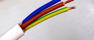
The Electrician's Bible PUE (Electrical Installation Rules) states: electrical wiring along its entire length should make it possible to easily recognize the insulation by its color.
In a home electrical network, as a rule, a three-wire conductor is laid, each wire has a unique color.
- Working zero (N) is blue, sometimes red.
- The neutral protective conductor (PE) is yellow-green.
- Phase (L) – can be white, black, brown.
In some European countries there are constant standards for the colors of wires by phase. Power for sockets - brown, for lighting - red.
An example of decoding cable markings.
To make it easier to understand the accepted conventions, consider several standard options.
- ANRBG 3X16 + 1X10. Cable with 3 aluminum cores (A), the cross-section of which without insulation is 16 square meters. mm (3X16). The design provides a neutral conductor with a cross-section of 10 square meters. mm (1X10). The insulation is made of non-flammable rubber (NR). The letter B in the abbreviation indicates the presence of armor made of steel tape, and the letter G indicates the absence of an external protective cover.
- AVVGng 3X2.5. The numbers in the cable marking indicate that it contains 3 cores with a cross-sectional area of 2.5 square meters. mm excluding insulation. Their base is aluminum (A). The second and third letters indicate that PVC (vinyl) was used for both conductor insulation and internal protective sheathing. Bare cable (G) does not support combustion (ng).
- VVGEng-LS 10X0.5. The basis of this cable is 10 copper cores (no A at the beginning) with a cross-sectional area of 0.5 square meters. mm (10X0.5). The conductors are insulated with PVC, which also formed the basis of the internal protective sheath (two V at the beginning of the marking). The presence of the letters G and E indicates that the cable is shielded, but does not have an external protective sheath. The addition of ng-LS indicates that combustion is not maintained and little smoke is emitted.
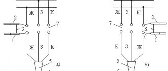
How to determine L, N and PE?
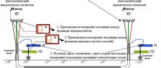
So, let’s imagine this situation: in the process of repairing a household electrical network, it happened that each of the conductors has the same color. How to determine which wire is L, which is N, and which is PE?
If a single-phase network has only 2 wires, then the problem can be resolved with a special indicator screwdriver. With its help, it’s easier than ever to determine exactly where the zero is and where the phase is. We have already talked about how to use an indicator screwdriver. First you need to turn off the electricity supply to the panel.
Afterwards you need to strip the two conductors and separate them in opposite directions. Now you can turn on the electricity supply and use the indicator to determine L and N. If the light bulb lights up upon contact with the core, this means it is a phase, while a light bulb that does not light up will mean zero.
If there is a ground wire in the electrical wiring, you will need to resort to electrical measuring equipment such as a multimeter. It is equipped with two tentacles. First you need to set the AC current measurement to more than 220 Volts. One of the tentacles is fixed on the phase contact. Using another tentacle, grounding and zero are determined.
When you touch zero, the electrical measuring device will display a voltage value in the region of 220 Volts. If you touch the “ground”, this indicator will be lower. More detailed operating instructions for this device were provided in a separate article, which we recommend that you read!
There is an alternative method of determination. If you don’t have an indicator screwdriver and a multimeter at hand, you can try to calculate the color of the wires by their insulation. In this case, it is important to remember that the blue shell will always be zero in any case. In the case of even the most non-standard markings, the color of the zero does not change. In the case of determining the remaining two cores, everything will be somewhat more complicated.
In the first possible option, you see the remaining colored contact, as well as a black or white contact. Previously, the earth was marked with black or white insulation. It is likely that this is it, and the remaining color is phase (L).
In the second possible option, we also discard the zero, concentrating on the red and black (or white) wire. If the insulation is white, then according to the PUE it is a phase. Then, the remaining red is ground.
Please note that the last method is extremely dangerous. If you decide to resort to it, be sure to make notes for yourself so that during the process of repairing an outlet or chandelier you do not get an electric shock!
In a DC circuit, the marking is represented by black (minus) and red (plus) insulation color. In the case of a three-phase network, each phase has its own individual color: phase A is yellow, B is green, and C is red. Zero is also blue, and grounding will have a yellow-green color.
For a 380V cable, wire A will be white, B will be black, and C will be red. The neutral protective and working conductors have markings similar to the last case.
Table for decoding letter markings of power cables.
In some cases, marking power cables (deciphering which for an untrained person seems like a real nightmare) can become a significant difficulty in tasks related to cable and wire products. In fact, deciphering the cable markings is not that difficult. The detailed meaning of each letter symbol of the cable brands is given in the cable catalog tab and the table below:
| Ordinal location - position of parts of the marking | Scope of product (cable) characteristics described by this part | Explanation of possible meanings of this part of the marking |
| 1st capital Latin letter (foreign markings only) | Compliance with standard | N - the cable is manufactured according to the German VDE standard; Li - stranded copper conductors made in accordance with VDE (for control cables it is placed at the end of the marking); H - harmonized wire (HAR approval); The absence of a letter means that the cable does not comply with foreign standards, or the standard is not indicated in the marking. |
| 1st group of numbers (foreign markings only) | Rated voltage | 05 - Rated voltage 300/500 V; 07 - Rated voltage 450/750 V; Often missing from labeling . |
| 1st capital letter | Conductor material | A - current-carrying conductor made of aluminum; AC - current-carrying conductor made of aluminum with a lead sheath; AA - the same, aluminum shell; No letter or space (underscore) - conductive conductor made of copper . |
| 2nd capital Latin letter (foreign markings only) | Insulation type | Y - Polyvinyl chloride (PVC) insulation; YH - Halogen-free polyvinyl chloride insulation; Y(ST) - insulation and sheath made of PVC plastic; This part of the marking is almost always present . |
| 2nd capital letter | Scope of application of the cable (wire, cord) | B - aviation (on-board aircraft) wires; K - control cable (not used for power cables); KP/KE - submersible cable; KN - oil submersible heating cable; G - cables for the mining industry (“mining” cable); M - installation wires and cables; P - wire; O - optical (not used for power cables); U - installation cable; Ш - cord; ШБ - household cord; E - for special mine conditions; KPS - twisted pair cable for alarm systems; Foreign markings: J - Cable for alarm systems; M - installation wires and cables; SL - Control cable; KG - flexible cable (in fact, it is not an independent designation and is a combination of the designation “K - cable” indicating the degree of flexibility (G - flexible); The absence of a letter means that this cable or wire is power . |
| 3rd capital letter | Degree of flexibility | K - flexible core for stationary installation (foreign markings only); G - “flexible”, as a rule, means that the structure is based on a stranded core; The letter G is missing - the cable is not intended for installation in moving structures or routes with complex geometry. In most cases, the conductor in such cables is a single-wire core. |
| 4th capital letter | Core insulation material | B - polyvinyl chloride (PVC); P - polyethylene; C - glass insulation; A - asbestos insulation; R - rubber; NR - non-flammable rubber; F - fluoroplastic; C - film insulation (for installation wires); For winding wires: EV - high-strength enamel; EL - varnish-resistant enamel; ET - heat-resistant enamel; B - cotton yarn; K - nylon; Ш - natural silk; ShK - artificial silk nylon; O - one layer of insulation (maybe the 4th letter); Absence of a letter - uninsulated conductors . |
| 5th capital letter | Availability of screen | E - general screen; C - presence of a copper screen (foreign markings only); Y - presence of a screen made of aluminum foil (foreign markings only); Absence of a letter means unshielded cable . |
| 6th capital letter | Sheath material for cable products, armored cover | RG - presence of armor (foreign markings only); B - armored cover (armor) made of steel tapes; BBG - armored cover made of steel profiled tape; Bn - armor made of steel strips, with a protective cover that does not support combustion; B - PVC; D - double wire; K - armor made of round galvanized steel wires, enclosed in a protective cover; SB - lead armor; Absence of a letter - cable without armor or without armor and outer sheath . |
| 7th capital letter | Type of protective cover. Purpose of the outer layer, designation of the core structure | V - PVC insulation (foreign markings only); B - PVC; -B - paper insulation (at the end of the designation); G - anti-corrosion protective layer; Absence of the letter G - protection from mechanical damage; O - insulated conductors are combined into a common sheath, braid (for wires); Png - shell made of a polymer composition; Shv - protective layer (or shell) - pressed PVC hose; Shp - the same, but made of cross-linked polyethylene; Absence of a letter - cable without additional outer layers . |
| Lower case | Additional performance characteristics. Lowercase letters are placed next to uppercase letters, without spaces. In some cases they may appear after the 7th capital letter. | c - vulcanized (polyethylene); d - water blocking tapes (used to seal a metal screen); h - filling between the cores; ng() - a shell made of non-combustible material. The flame retardation class (capital letter) is indicated in parentheses. If there is no value in brackets, then the cable has flame retardation class A; b - without a pillow; l - the pillow contains lavsan tape; 2l - the pillow contains a double lavsan ribbon; c - self-extinguishing; E - shielded; T - the wire is intended for installation in pipes; Absence of a letter - no additional design characteristics . |
| 8th capital letter | Operational characteristics: design features, climatic design, etc. | U - paper insulation with increased heat resistance; -P - flat design (as practice shows, this designation can be located anywhere on the marking, and is also often indicated by the lowercase letter “p”. For example: “VVGPng-LS”, “VVGpng-LS”, “VVGngp-LS”, and "VVGng-LS-P."); FR - fire-resistant cable; HF - halogen-free cable; LS - cable with reduced smoke and gas emissions; LTx - reduced level of toxicity of combustion products; Climatic version: -HL - cold resistance; T - increased resistance to thermal effects; Absence of a letter means no special performance characteristics . |
| Lowercase letters in brackets (can be indicated without brackets at the end of the marking, after the numbers) | Core type | cooler - single-core design; mn - multi-core design (for more details, see the article “Abbreviations for designating the type of conductor of cable and wire products when marking cables: ozh, mn, ok, os, ms”); Absence of a letter - the type of execution is not specified . |
| 1st digit (in some cases 3rd) | Rated voltage | 1 - rated cable voltage (example), kV; No number - low voltage cable up to 660 V. |
| 2nd digit (usually the 1st, always comes before the multiplication symbol - “X” or “*”) | Number of cores | 1- 4 - power cables; 2-14 - installation cables; 4-37 - control cables |
| 3rd digit (usually the 2nd, always follows the multiplication symbol - “X” or “*”) | Core cross-section, mm² | 0.75-10 — control cables 0.35 — 0.75 — installation cables |
| A group of digits separated by a multiplication symbol immediately following the "+" sign | The presence of neutral conductors with a cross-section different from the cross-section of the current-carrying conductors. | For example: +1X120. The cross-section of the neutral conductor according to the PUE is 50% of the cross-section of the main current-carrying conductor, provided that the cross-section of the supply conductor is more than 25 mm2; Absence of designation - the neutral conductor is missing, or the cross-section coincides with the current-carrying ones . |
| Capital or lowercase Latin letters at the end of the marking | The presence of a neutral conductor and a grounding conductor with the same cross-section as the current-carrying conductors. | N – the cable contains a neutral core; N, PE - the cable contains a neutral conductor and a grounding conductor; (for more details, see the article “Abbreviations for designating the type of conductor of cable and wire products when marking cables: ozh, mn, ok, os, ms”); Lack of designation - the neutral conductor and the grounding conductor are either absent in the cable design, or not indicated in the marking, or the neutral conductor has a different cross-section from the current-carrying conductors . |
According to the provisions of GOST R 53769-2010, when marking cables, after indicating the cross-section, you can add special abbreviations that indicate the design of the cores. The designation “ok” is used for a single-wire round conductor, “mk” for a multi-wire round conductor, “os” for a single-wire sector conductor, and “ms” for a multi-wire sector conductor.
In a single-core wire, there is only one conductive core under the insulation, in contrast to a stranded wire, which uses several cores as an electrically conductive element. plastic pipes www.wavinekoplastik.ru water distribution The cross-section is determined based on only one core. The main feature of a single-core wire is its ease of installation, since connecting it to a circuit breaker or special terminals is much easier than multi-core. Also, its use increases the convenience and speed of installation of lighting fixtures, switches or household sockets.
Twisting of several single-core wires lends itself well to subsequent welding or crimping. And thanks to their rigidity, they can perfectly retain their given shape when placed in boxes. The disadvantages of this type of cable product is its susceptibility to bending, since this can damage the core. The cross-section is determined based on only one core.
Stranded wires are more flexible, so they are better suited for laying in boxes that have a lot of turns. In addition, they have high elasticity and vibration resistance. It is advisable to use them in distribution and switching boxes with a high number of connections. In such cables, the cross-section is calculated taking into account all the cores, which can run parallel or be twisted relative to each other. Often a special dielectric thread is added to the cores, which increases the strength of the cable.
Knowing about wires and cables is as important as knowing about the miniplate. Minplyta is a mineral insulation material that is well used for insulating main coolant systems. Minslab is also used as the main thermal insulation material in other industrial pipeline systems.
The main feature of stranded wires is high conductivity of electric current and low heating rates, which is achieved due to the surface conductivity effect. However, the cost of such products is higher compared to single-core wires, and there are certain restrictions when using them in high-frequency electrical circuits.
The choice of cable should be based on the above features. Single-core ones are most often used for organizing wiring, supplying to various electrical installations and in cases where it is necessary to remove electricity from industrial generators. And multi-core ones are used where increased flexibility is required, for example, in electrical systems in transport. They are also used to organize temporary power supplies, in extension cords and in cases where it is necessary to make repeated bends.
When designing, do not forget about the permissible bending radius of the cable, which directly depends on the outer diameter D. Thus, for power cables with paper insulation, the permissible bending radius is:
for stranded - 15D,
for single-core - 25D.
For power cables with rubber or plastic insulation:
for multi-core – 0.7D,
for single-core - 10D.
For control cables, the bending radius is allowed within 6-12 diameters, depending on the type of sheath.
The cross-sectional area of the cable is a very important indicator, therefore at the design stage this parameter should be calculated depending on the rated current, which is determined taking into account all connected loads. Knowing the rated current, the optimal wire cross-section can be easily selected from special calculation tables, which are given in most reference books on electrical engineering or in design guidelines.
Standard cable cross-sections with copper conductors range from 0.5 to 800 sq. mm., and aluminum - from 2.5 to 800. At the same time, copper wires with a cross-section of up to 10 sq. mm. and aluminum with a cross section of up to 25 square meters. mm. can be either single-core or multi-core. Wires with a large cross-section are made only stranded.
This is where we will finish our article on multi-core and single-core cables and wires. If our dear reader still has any questions about cable and wire products, then you can leave your question in the comments below, or in the “Questions and Answers” section of the site.
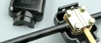
Marking of cable lines.
Wires and cables laid in boxes and on trays must be marked at the beginning and end of the trays and boxes, as well as at the points where they are connected to electrical equipment, and the cables, in addition, also at route turns and branches. Each cable line must be marked and have its own number or name. Labels must be installed on exposed cables and cable joints. Tags must be secured to the cables with nylon thread or galvanized steel wire with a diameter of 1 - 2 mm, or plastic tape with a button. The place where the tag is attached to the cable with wire and the wire itself in damp rooms, outside buildings and in the ground must be covered with bitumen to protect it from moisture. On hidden cables in trenches, tags are installed at the end points and at each coupling. Tags should be used: in dry rooms - made of plastic, steel or aluminum; in damp rooms, outside buildings and in the ground - made of plastic. Designations on tags for underground cables and cables laid in rooms with a chemically active environment should be made by stamping, punching or burning. For cables laid in other conditions, markings may be applied with indelible paint. On cables laid in cable structures, tags must be installed at least every 50 - 70 m, as well as in places where the direction of the route changes, on both sides of passages through interfloor ceilings, walls and partitions, in places where cables enter (exit) into trenches and cable structures. On hidden cables in pipes or blocks, tags should be installed at the end points at the end couplings, in the wells and chambers of the block sewer system, as well as at each connecting coupling.
Basic requirements for separating PEN conductor
Everything you need to know to competently carry out such work is spelled out in the provisions of the PUE. In particular, the need for such a connection is stated in paragraph 7.1.13
How the connection should look on the diagram is described in paragraph 1.7.135 - when in any place of the REN the conductor is divided into neutral and ground wires, their subsequent combination is not allowed.
Once separated, the tires are considered different and must be marked accordingly - zero is blue, and PE is marked yellow-green.
The jumper between the grounding bus and the neutral one is made of a material with a cross-section no smaller than the buses themselves, from which the PE and N wires go further. In this case, the protective conductor bus PE can be in contact with the transformer body, and the n bus is separately installed on insulators. The PE bus must be grounded - ideally there should be a separate circuit for it (PUE - 1.7.61).
When using RCD devices, the zero used to connect electrical equipment should not be in any way in contact with the zero that comes to the input machine and the meter. All these devices are connected using this principle.
The place where the PEN conductor is divided into PE and N wires, for a number of reasons, is in the ASU, which is located at the entrance to an apartment building or private building.
The PEN wire, which will be divided into working zero and grounding, must have a cross-section of at least 10 mm² if it is copper, and 16 squares if it is aluminum. Otherwise, division is prohibited.