Let us have an alternating current generator with three separate windings located at an angle of $120^0$ relative to each other. Three-phase current is created in these windings. The voltage on the windings is:
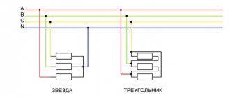
If this generator is used without communication with each other, then the three-phase current generator becomes simply a collection of individual single-phase current generators. If the windings are connected in a certain way, then the three-phase current develops special properties that are used in technology. Two types of generator winding connections are used: “star” and “delta” .
Star and triangle connection principle. Features and operation
To increase the transmission power without increasing the network voltage, to reduce voltage ripple in power supplies, to reduce the number of wires when connecting the load to the power supply, various circuits for connecting the windings of power sources and consumers (star and delta) are used.
Scheme
The windings of generators and receivers when working with 3-phase networks can be connected using two circuits: star and triangle. Such circuits have several differences among themselves; they also differ in current load. Therefore, before connecting electrical machines, it is necessary to find out the difference in these two circuits - star and triangle.
Star diagram
Connecting different windings according to a star circuit involves connecting them at one point, which is called zero (neutral), and is designated on the diagrams “O”, or x, y, z. The neutral point may have a connection to the power supply neutral point, but not all cases have such a connection. If there is such a connection, then such a system is considered 4-wire, and if there is no such connection, then it is considered 3-wire.
Triangle diagram
With this scheme, the ends of the windings are not combined into one point, but are connected to another winding. That is, the result is a circuit similar in appearance to a triangle, and the windings in it are connected in series with each other. It should be noted that the difference from the star circuit is that in the delta circuit the system is only 3-wire, since there is no common point.
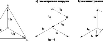
In a triangle circuit, when the load is off and the EMF is symmetrical, it is 0.
Phase and linear quantities
In 3-phase power networks there are two types of current and voltage - phase and linear. Phase voltage is its value between the end and beginning of the receiver phase. Phase current flows in one phase of the receiver.
When using a star circuit, the phase voltages are Ua, Ub, Uc , and the phase currents are I a, I b, I c . When using a delta circuit for load or generator windings, phase voltages are Uaв, Ubс, Uca , phase currents are I ac, I bс, I са .
Linear voltage values are measured between the beginnings of phases or between linear conductors. Line current flows in the conductors between the power source and the load.
In the case of a star circuit, linear currents are equal to phase currents, and linear voltages are equal to U ab, Ubc, U ca. In a triangle circuit, everything turns out the other way around - phase and linear voltages are equal, and linear currents are equal to I a, I b, I c .
Great importance is given to the direction of the EMF of voltages and currents in the analysis and calculation of 3-phase circuits, since its direction affects the relationship between the vectors on the diagram.
Features of the circuits
There is a significant difference between these schemes. Let's figure out why different circuits are used in different electrical installations, and what their features are.
When starting an electric motor, the starting current has an increased value, which is several times greater than its rated value. If this is a low-power mechanism, then the protection may not work. When a powerful electric motor is turned on, the protection will definitely work, turning off the power, which will cause a voltage drop for some time and blown fuses, or turn off the electrical circuit breakers. The electric motor will operate at a low speed, which is less than the rated speed.
It can be seen that there are many problems arising due to the high inrush current. It is necessary to somehow reduce its value.
To do this, you can use some methods:
- Connect a rheostat, inductor, or transformer to start the electric motor.
- Change the type of connection of the electric motor rotor windings.
In industry, the second method is mainly used, since it is the simplest and gives high efficiency. The principle of switching the windings of an electric motor to circuits such as star and triangle works here. That is, when the motor is started, its windings have a “star” connection, after a set of operating speeds, the connection diagram changes to “triangle”. They have learned to automate this switching process in industrial settings.
In electric motors, it is advisable to use two circuits at once - star and triangle. It is necessary to connect the neutral of the power source to the zero point, since when using such circuits there is an increased likelihood of phase amplitude distortion. The source neutral compensates for this asymmetry, which arises due to different inductive resistances of the stator windings.
Advantages of the schemes
Star connection has important advantages:
- Smooth start of the electric motor.
- Allows the electric motor to operate with the declared rated power corresponding to the passport.
- The electric motor will have a normal operating mode in various situations: with high short-term overloads, with long-term minor overloads.
- During operation, the motor housing will not overheat.
The main advantage of the triangle circuit is to obtain the highest possible operating power from the electric motor. It is advisable to maintain operating modes according to the engine passport. When studying electric motors with a triangle circuit, it turned out that its power increases 3 times compared to a star circuit.
When considering generators, the star and delta circuits are similar in parameters to the operation of electric motors. The output voltage of the generator will be higher in a delta circuit than in a star circuit. However, as the voltage increases, the current decreases, since according to Ohm's law these parameters are inversely proportional to each other.
Therefore, we can conclude that with different connections of the ends of the generator windings, two different voltage ratings can be obtained. In modern powerful electric motors, when starting the circuit, star and delta switch automatically, as this makes it possible to reduce the current load that occurs when starting the motor.
Star, triangle - definitions
Depending on the method of connecting the generator windings and the load, a distinction is made between star and delta connections. Each phase winding of the generator has two terminals, which are conventionally called the beginning and the end. The beginning of the winding is taken to be the terminal to which the positive EMF is directed.
When connected by a star, the ends of all phases of the generator are connected into one node. It is called the neutral node or neutral point. The neutral points of the generator and the load are often connected with a neutral (neutral) wire. The remaining wires connecting the generator windings to the receiver are called linear.
In a delta connection, the beginning of one phase winding is connected to the end of the next so that the three windings form a closed triangle.
In practice, various combinations of generator and load phase connections are used: star-star, star-delta, delta-delta. There are also combinations with a zigzag, but we will not touch on them in this review.
Voltages and currents in the generator and load phases are called phase and are designated Uph, Ia. The voltages between linear wires and the currents in them are called linear and are designated Ul, Il. From the diagrams discussed above it follows that when connected by a star, Il = Iph, and when connected by a triangle, Ul = Uph.
If the windings of a 220 Volt power source are connected in a triangle, the phase and line voltages are respectively equal to 220 Volts. The relationships between linear and phase voltages when connected by a star are already different. You can find them using a vector diagram or by analyzing sinusoids of three phases, as shown in the following video:
Calculation of linear voltage by vectors comes down to the analysis of an isosceles triangle with base angles of 30°. You can also calculate the difference between vectors using complex numbers. We will not dwell on these methods in detail. Let us only note the consequence - when connected by a star, the linear voltage Uл = √3 × Uф (380 = √3 × 220).
Connecting energy receivers in a triangle
When connecting energy receivers with a triangle (Fig. 6-11), each phase of the receiver is connected to the linear wires, i.e., it is switched on to the line voltage, which will also be the phase voltage of the receiver:
Thus, changing the phase resistance does not affect the phase voltages.
We will take the directions of linear currents from the generator to the receiver as positive (Fig. 6-11). Directions of phase currents from A'
to
B',
from
B'
to
C
' and from
C'
to
A'
will also be taken as positive.
According to Kirchhoff's first rule for instantaneous current values for node A'
you can write:
Similarly for node B':
Rice. 6-11
. Connecting receivers in a triangle
Consequently, the instantaneous value of any line current is equal to the algebraic difference of the instantaneous values of the currents of those phases that are connected to a given wire.
Rice. 6-12.
Vector diagram when connecting receivers in a triangle.
The vector of any line current is found as the difference between the vectors of the corresponding phase currents:
In Fig. 6-12 shows a vector diagram for a three-phase circuit when connecting energy receivers with a triangle. In this diagram, all vectors are drawn from the same origin. In Fig. 6-13 shows a second diagram for the same circuit, on which the voltage vectors form a triangle, and the vector of each phase current is drawn from the same origin with the vector of the corresponding phase voltage.
Rice. 6-13.
Vector diagram when connecting receivers in a triangle.
If, with a symmetrical system of linear voltages, the phase load is uniform, i.e.
then the effective values of the phase currents are equal to each other and they are shifted in phase by equal angles from the corresponding voltages (Fig. 6-14) and, therefore, by angles of 120° relative to each other. Therefore, the phase currents represent a symmetrical system. Linear currents will also represent a symmetrical system (Fig. 6-14).
By restoring the perpendicular from the middle of the linear current vector, for example IA,
we obtain a right triangle
OHM,
from which it follows that
Thus, when connecting receivers in a triangle with a uniform phase load, the linear currents are √3 times greater than the phase currents.
In addition, from the same vector diagram it follows that linear currents lag behind the corresponding phase currents at angles of 30°.
Rice. 6-14.
Vector diagram for a circuit connected by a triangle with a uniform phase load.
When connecting receivers in a triangle with a uniform phase load, the calculation of a three-phase circuit is reduced to the calculation of one phase.
in phase voltage are determined from the expressions
Active power of one phase
Three phase reactive power
Three-phase apparent power
If the phase load is uneven, the power of a three-phase circuit is determined as the sum of the powers of the individual phases.
If the energy receivers are connected by a star and the positive direction of the linear currents is taken to be the direction from the generator to the consumer, then according to Kirchhoff’s first rule for the neutral point we can write:
If the energy receivers are connected by a triangle, then the sum of the line currents
Consequently, for any method of connecting receivers, the algebraic sum of the instantaneous values of the linear currents of a three-phase three-wire circuit is equal to zero.
Therefore, for example, the magnetizing force of the three cores of a three-phase cable is zero and, therefore, there is no magnetization of the steel armor of the cable used to protect against mechanical damage.
Options for connecting windings of three-phase generators
When a 3-phase generator operates, an EMF is created in each of its windings in the form of a sinusoidal oscillation. All vectors are separated by 120° in rotation angle and can be described by the formulas:
eA=Emsinωt, EA=Efej0°; eB=Emsin(ωt-120°), EV=Efe-j120°; eC=Emsin(ωt-240°)=Emsin(ωt+120°), EC=Efej120°.
To connect the generator windings to a connected system, one of two schemes is used:
— “star” (Y); — “triangle” (Δ).
"Star"
.
For the “star” circuit, all outputs of the stator phase windings are connected to a single common point N
, called the neutral or zero point.
The input (start) of the windings of each phase A, B and C
is connected to the linear terminals of the generator.
"Triangle"
. For this connection diagram, the output phases are formed:
— "A"
connecting the output of winding
A
to the input of winding
C
; -
“B”
connecting the output of winding
B
to the input of winding
A
; -
“C”
connecting the output of winding
C
to the input of
winding B.
Connection points A, B and C
used as linear outputs for the generator.
Vector diagrams
. For a working generator, the windings of which are connected in a star configuration, the voltage vector diagram has the shape of an equilateral triangle with the center at the origin and located symmetrically relative to the ordinate axis.
Its sides are represented by linear stress vectors with the direction of rotation opposite to the clockwise direction. The phase voltage vectors connect the center of the triangle with the vertices in the direction from the origin.
The term phase voltage refers to the potential difference between the common terminal N and the linear terminal A, B
or
C
and mark:
UA, UB, UC
.
The voltages in the generator phases are equal to the EMF of the windings: EA=UA, EB=UB, EC=UC
.
The linear voltage of the generator is measured between any two of its terminals and is designated by the name of the selected phases: UAB, UBC, UCA
. The magnitude of the line voltage vector is determined by the geometric difference between the vectors of the corresponding phases:
UAB=UA-UB; UBC=UВ-UC; UCA =UC-UA.
For a generator with windings connected in a “triangle” pattern, the voltage vector diagram also has the shape of an equilateral triangle, but it is rotated 30° relative to the coordinate center in the direction of clockwise movement.
The ratios of linear and phase voltages for a generator assembled according to a “delta” circuit remain the same as for a generator operating according to a “star” circuit.
Calculations of the parameters of three-phase networks are carried out using mathematical methods (for example, the complex method) and methods of geometric addition.
To do this, select one of the vectors as the initial one and orient it in the complex plane, taking into account the direction and magnitude. The remaining vectors are completed according to the angles of their phase shift relative to the selected initial vector, taking into account their values.
It is easier to start usual calculations for a star connection circuit by determining the voltage of the phase A
, which in this system leaves the origin of the complex plane in the direction to the north. Expressions of phase voltages in complex form for such a calculation are described by the formulas:
UA=Ufej0°; UВ=Uе-j120°; UС=Uеj120°
.
Formulas for linear vectors are as follows:
UАВ=Ulej30°; UВС=Ule-j90°; UCA=Ulej150°.
For “triangle” circuits, the linear voltage vector UАВ
. Formulas for calculating phase voltage vectors take the following expressions:
UA=Ufe-j30°; UВ=Uе-j150°; UC=Ufej90°.
Linear voltage vectors are described by the formulas:
UАВ=Ulej0°; UВС=Ule-j120°; UCA=Ulej120°.
Having carried out geometric calculations, it is not difficult to determine the linear magnitude of the vector from the phase value:
Ul=2Uфcos30°=2Uф√3/2=Uф√3.
Important!
The “delta” winding connection diagram for a generator is practically not suitable for real use, so it is prohibited to use it.
In the phases of the “triangle” circuit, a common circuit is formed, in which a total EMF arises Σe=eAB+eBC+eCA
.
The values of the total resistance in the windings are small and even a small value of the total EMF Σe>0
causes equalizing currents in the “triangle” mains, which are comparable to the rated current value in the generator. This creates large energy losses and significantly reduces the generator efficiency.
Power engineers have a definition of the rated voltage for a 3-phase system. They are called linear voltages, which are expressed in kilovolts (kV, kV). They are represented by values of 0.4; 1.1; 3.5; 6.3; 10.5; 22; 35; 63; 110; 220; 330; 500; 750.
For electricity consumers, the nominal value of 3-phase voltage can be indicated by the ratio of linear and phase voltages UЛ/UФ
. For a 0.4 kV power network it will look like: 380/220 volts.
INCLUSION OF ENERGY RECEIVERS INTO THE THREE-PHASE CURRENT NETWORK
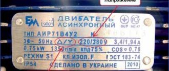
Electric lamps are manufactured for rated voltages of 127 and 220 V, and three-phase electric motors for rated phase voltages of 127, 220 and 380 V
and higher.
The method of connecting the receiver to a three-phase current network depends on the line voltage of the network and on the rated voltage of the receiver.
Lamps with a nominal voltage of 127 V
switched on by a triangle at a linear network voltage of 127
V
and a star with a neutral wire at a linear network voltage of 220
V.
Lamps with a rated voltage of 220
V
are connected by a triangle into a network with a linear voltage of 220
V
and a star with a neutral wire into a network with a linear voltage of 380
V.
A three-phase electric motor is connected by a delta into a network whose line voltage is equal to the rated phase voltage of the electric motor. If the line voltage of the network exceeds √3 times the rated phase voltage of the electric motor, then it is turned on as a star.
Article on the topic Connecting energy receivers with a triangle
Star connection of transformer windings
When connected into a star, the following relations apply:
- line currents are equal to phase currents,
- linear voltages are √3 times greater than phase voltages
There are many options for connecting the transformer windings in a star, some of them are shown in the figure below. And, as they say, not all of them are equally useful, or rather, different connection diagrams are needed for different cases.
It should be noted that either one three-phase transformer or three single-phase ones can be connected into a star. The figure indicates:
- A, B, C – the beginning of the high voltage windings
- X, Y, Z – ends of high voltage windings
- a, b, c – the beginning of the low voltage windings
- x, y, z – ends of low voltage windings
Connection of transformer windings in a triangle
The triangle connection is so called because of its external resemblance to a triangle (seen in the figure).
When connected into a triangle, the following relations apply:
- linear currents are √3 times greater than phase currents
- line voltages are equal to phase voltages
The three secondary windings, when connected in a delta, are connected in series, thereby forming a closed circuit. There is no current in this circuit, since the EMF of the phases are shifted by 120 degrees and their sum at each moment of time is zero. Also, the current is zero if the following conditions are met: the EMF has a sinusoidal shape, the windings have the same number of turns.
Star and triangle in the question of third harmonics of transformers
In transformers, the triangle circuit is used, among other things, to obtain third harmonic currents, which are necessary to create a sinusoidal EMF of the secondary windings. In other words, to eliminate the third harmonic component in the magnetic flux.
To introduce third harmonics when connecting to a star, the neutral of the star is connected to the neutral of the generator, and the third harmonics begin to run along this path.
Triangular Voltage Generator
The simplest way to obtain triangular pulses is a circuit containing a Schmitt trigger and an integrator, with the output of the trigger connected to the input of the integrator, and the output of the integrator to the input of the Schmitt trigger. Despite its simplicity, the circuit allows you to obtain good triangular pulses.
Triangular voltage generator.
This triangular voltage generator consists of a Schmitt trigger on op-amp DA1 and resistors R1, R2 and R3, as well as an integrator on op-amp DA2 and resistors R4, R5 and capacitor C1. Triangular pulses are removed from the “UOUT 2” pin; in addition, rectangular pulses can be removed from the “UOUT 1” pin. Resistors R3 and R5 serve to compensate for the op-amp bias voltage and, in cases where there is no need for strong pulse symmetry, they can be replaced with jumpers.
To understand the operating principle of the triangular pulse generator, consider a graph of the voltages at its terminals UOUT 1 and UOUT 2.
Graphs of the output voltages of the triangular pulse generator: at the output of the Schmitt trigger (upper) and at the output of the integrator (lower).
Suppose, after supplying the supply voltage to the circuit, the output of the Schmitt trigger (DA1) establishes a positive saturation voltage of the op-amp UNAC+, then capacitor C1 begins to charge, and at the output of the integrator (DA2), the voltage begins to drop linearly accordingly. Since the output of the integrator and the input of the trigger are combined, when the linearly decreasing voltage reaches the level of the lower switching voltage of the trigger UNP, the voltage at its output will transfer to the negative saturation voltage of the op-amp UNAC-, and the capacitor C1 will begin to discharge. As the capacitor discharges, the voltage at the integrator output will begin to increase linearly to the level of the upper switching voltage of the Schmitt trigger UВП, after reaching which the trigger output will switch to the level of the positive saturation voltage of the op-amp UNAC+ and the charging and discharging cycle of capacitor C1, and therefore the triangular voltage, will repeat.
From the above, we can conclude that the amplitude of the output triangular voltage, which can be removed from the output of op-amp DA2 (UOUT 2) will be equal to the hysteresis value of the Schmitt trigger
Thus, by adjusting the trigger hysteresis value, you can increase or decrease the amplitude of the triangular voltage output pulses.
The duration of the triangular pulse consists of two periods: a rise period with a duration of tH and a voltage drop period with a duration of tC. The duration of these periods is determined by the following expressions
As is known, the threshold levels of the Schmitt trigger with a reference voltage equal to zero (UOP = 0 V) are determined by the following expressions
Then, after simple transformations and substitutions, we obtain an expression for the duration and frequency of the triangular voltage
Changing the repetition rate of triangular pulses is carried out using resistor R4 (fine adjustment) and capacitor C1 (rough), although the duration of the pulses also depends on the resistance value of resistor R4.
It is worth noting that the maximum pulse repetition rate is limited by the parameters of the op-amp, in particular the rate of rise of the output voltage of op-amp DA2 (integrator) and the maximum output current of op-amp DA1 (Schmitt trigger).
Connecting transformer windings in a zigzag
A zigzag connection is used when there is uneven load on the secondary loads. After the zigzag connection, the load is distributed more evenly across the phases and the magnetic flux of the transformer remains in balance despite the uneven load.
Consider the zigzag star connection of a three-phase power transformer. A schematic representation is shown in the figure.
The primary windings are connected in a star. Next, we divide each secondary winding in half. And then we connect as shown in the figure.
When connecting into a zigzag star, a larger number of turns will be required than with a simple star. Also, with this connection it is possible to obtain three voltage classes, for example 380-220-127V.
Bookmark or share with friends
Source: pomegerim.ru
§ 79. Triangle connection
In addition to a star connection, generators, transformers, motors and other three-phase current consumers can be connected in a delta.
In Fig. 179 shows an uncoupled three-phase system. By combining the wires of an unconnected six-wire system in pairs and connecting the phases as indicated in the drawing, we move on to a three-phase three-wire system connected by a triangle.
Rice. 179. Uncoupled three-phase system
As can be seen from Fig. 180, the delta connection is made so that the end of phase A is connected to the beginning of phase B, the end of phase B is connected to the beginning of phase C, and the end of phase C is connected to the beginning of phase A. Line wires are connected to the phase connections.
Rice. 180. Connected three-phase delta-connected system
If the generator windings are connected by a triangle, then, as can be seen in Fig. 180, line voltage is created by each phase winding. For a delta-connected consumer, the line voltage is connected to the phase resistance terminals. Therefore, when connected by a triangle, the phase voltage is equal to the linear voltage:
Let us determine the relationship between phase and linear currents when connected by a triangle, if the load of the phases is the same in size and nature. We compose the current equations according to Kirchhoff’s first law for three nodal points A 1, B 1 and C 1 of the consumer:
From this it can be seen that the linear currents are equal to the geometric difference of the phase currents. With a symmetrical load, the phase currents are equal in magnitude and shifted one relative to the other by 120°. By subtracting the phase current vectors according to the resulting equations, we obtain linear currents (Fig. 181). The relationship between phase and line currents when connected in a triangle is shown in Fig. 182:
Rice. 181. Phase and line currents when connected by a triangle
Rice. 182. Dependence between phase and linear currents when connected by a triangle
Therefore, with a symmetrical delta-connected load, the line current is √3 times the phase current.
In Fig. 183 shows a vector diagram of currents and voltages for a uniform active-inductive load connected by a triangle. The diagram is constructed as follows. On the selected scale, we build an equilateral triangle of linear network voltages UAB, UBC AND UAC, which are equal to the phase voltages of the consumer. In the direction of the lag at angles φAB, φBC, φCA to the linear voltages UAB, U BC and UCA, we plot the phase current vectors IAB, IBC and ICA on a scale. Then, as stated earlier, we determine the line currents IA, IB and IC.
Rice. 183. Vector diagram of currents and voltages with a uniform load connected by a triangle
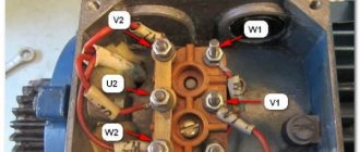
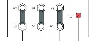
For motors and other consumers of three-phase current, in most cases, all six ends of the three windings are brought out, which, if desired, can be connected either by a star or a triangle. Usually a board made of insulating material (terminal board) is attached to a three-phase machine, to which all six ends are brought out.
Connection diagrams for triangle and star windings for dummies.
The most common question for those beginning to study the design of transformers or other electrical devices is “What are star and triangle?” We will try to explain in our article how they differ and how they are structured.
Let's consider the winding connection diagrams using the example of a three-phase transformer. In its structure, it has a magnetic circuit consisting of three rods. Each rod has two windings - primary and secondary. High voltage is applied to the primary, and low voltage is removed from the secondary and goes to the consumer. In the symbol, the connection diagram is indicated by a fraction (for example, Y⁄∆ or Y/D or U/D), the numerator value is the connection of the high voltage (HV) winding, and the denominator value is the low voltage (LV).
Each rod has both a primary winding and a secondary winding (three primary and three secondary windings). Each winding has a beginning and an end. The windings can be connected to each other using a star or delta method. For clarity, let us denote the above schematically (Fig. 1)
When connected by a star, the ends of the windings are connected together, and three phases go from the beginning to the consumer. From the terminal connections of the ends of the windings, the neutral wire N (also known as neutral) is removed. The result is a four-wire, three-phase system, which is often found along overhead power lines (Fig. 2)
The advantages of this connection scheme are that we can get 2 types of voltage: phase (phase + neutral) and linear. In such a connection, the linear voltage is √3 times greater than the phase voltage. Knowing that the phase voltage gives us 220V, multiplying it by √3 = 1.73, we get approximately 380V - linear voltage. But as for the electric current, in this case the phase current is equal to the linear one, because Both linear and phase currents leave the winding in the same way, and it has no other path. It is also worth noting that only in the star connection there is a neutral wire, which is a load “equalizer” so that the voltage does not change or jump.
Let us now consider the connection of the windings with a triangle. If we connect the end of phase A to the beginning of phase B, connect the end of phase B to the beginning of phase C, and connect the end of phase C to the beginning of phase A, we will get a triangle winding connection diagram. Those. in this circuit the windings are connected in series. (Fig. 3)
Basically, this connection scheme is used for symmetrical loads, where the load does not change between phases. In such a connection, the phase voltage is equal to the linear voltage, but the electric current, on the contrary, is different in such a circuit. The linear current is √3 times greater than the phase current. The delta connection of the winding provides ampere-turn balance for zero current
sequences. In simple terms, the delta connection circuit provides balanced voltage.
Let's summarize. For a basic definition of power transformer winding connection diagrams, it is necessary to understand that the difference between these connections is that in a star, all three windings are connected together by one end of each winding at one (neutral) point, and in a triangle, the windings are connected in series. The star connection allows us to create two types of voltage: linear (380V) and phase (220V), and in a triangle only 380V.
The choice of winding connection diagram depends on a number of reasons:
- Transformer power circuits
- Transformer power
- Voltage level
- Load asymmetry
- Economic considerations
For example, for networks with a voltage of 35 kV and more, it is more profitable to connect the transformer winding with a star circuit, grounding the zero point. In this case, it turns out that the voltage of the transformer terminals and transmission line wires relative to the ground will always be √3 times less than linear, which will lead to a reduction in the cost of insulation.
In practice, the following groups of compounds are most often encountered: Y/Y, D/Y, Y/D.
The group of winding connections Y/Y (star/star) is most often used in low-power transformers that supply symmetrical three-phase electrical appliances/receivers. It is also sometimes used in high-power circuits when grounding of the neutral point is required.
The winding connection group D/Y (delta/star) is used mainly in high-power step-down transformers. Most often, transformers with such a connection operate as part of power supply systems for low-voltage current distribution networks. Typically, the star's neutral point is grounded to accommodate both line-to-line and phase-to-phase voltages.
The Y/D (star/delta) winding connection group is mainly used in the main transformers of large power stations and non-distribution substations.
Source: www.forwardenergo.ru
Voltage transformation using star and delta combinations
With a power plant generator power of 500 MW and a voltage of 10 kV, the current in the wires will be 50 thousand amperes. When transmitting over long distances, wires, as a load, have significant resistance. Consequently, most of the current will be wasted heating the wires. To minimize losses during the transportation of electricity, the only effective way is to increase the voltage, which will lead to a decrease in current. But without distribution transformers (step-up and step-down) this cannot be done.
Now we will not dwell in detail on the principle of operation of the transformer. We are more interested in the peculiarity of connecting its windings with a star or triangle.
We will simulate in the Multisim program. Let's start drawing the circuit with a three-phase generator, the windings of which are connected in a star. We ground the connection point of the windings. At this stage, we note that despite the fact that generators at power plants generate voltages of thousands of volts and transform it all the way by increasing and decreasing, we will take a generator that generates 220 volts that we understand. Also, you should not compare the diagrams shown here with a real system, since the path from the power plant to the consumer is much more complicated.
Now let's add a transformer. More precisely, we will assemble it from three transformers in such a way that the primary winding is connected in a star, and the secondary in a triangle. We will not increase the voltage, but let’s see what transformation occurred when connecting the transformer windings according to the star-delta circuit.
When switching from star to delta windings of generators or secondary windings of transformers, the following occurs:
- The network voltage decreases by 1.73 times. In our case, the line voltage is reduced from 380 to 220 Volts.
- The power of the generator and transformer remains the same. And all because the voltage of each phase winding remains the same and the current in each phase winding is the same, although the current in the linear wires increases by 1.73 times. We will show this a little later, when we close the circuit through consumers. But first, let’s add another transformer with a delta-star circuit to our circuit and connect the load to it.
When switching generator windings or secondary windings of transformers from delta to star, the opposite phenomena occur:
- The line voltage in the network increases by 1.73 times. In our case, from 220 to 380 Volts.
- The currents in the phase windings remain the same, the currents in the linear wires decrease by 1.73 times.
Now let's understand the reasons for transformations in simple words without using vectors. To do this, consider the movement of free electrons in a circuit and analyze the potentials at a specific moment in time. You probably won’t see this explanation anywhere, but it is perhaps the easiest to understand.
The first thing in our chain is the generator. Simply put, it has three stator windings offset by 120° relative to each other. When the rotor rotates, a periodically varying EMF with an amplitude of approximately 312 Volts appears in the stator windings. This is the amplitude value of the voltage, and we will not move from it to the actual voltage. At the moment when the voltage at one of the generator terminals is +312 Volts, at the other two -156 Volts. Let's stop at this point and move on to the voltages of the transformer windings.
The voltages at the considered moment in time both on the primary winding and on the secondary winding correspond to the +312, -156, -156 Volts highlighted above. So why do the currents in the linear wires extending from the triangle windings increase by the root of three times, and the linear voltage decreases by the same amount? The whole secret is in particular the connection of the windings in a triangle, and then we will clearly demonstrate this by moving to a more simplified diagram.
Since in a delta connection the beginning of one phase winding is connected to the end of the next, the winding voltage of +312 Volts will be distributed between the winding with a voltage of -156 Volts and the output. As a result, the output of the winding with a voltage of +312 Volts will be +156 Volts, and the output of the winding with a voltage of -156 Volts will be 0 Volts. We are left with the third winding with a voltage of -156 Volts, and at its output it will remain -156 Volts. As a result, we get the output voltage at the moment we considered +156, -156, 0 Volts (and it was +312, -156, -156 Volts).
The resulting linear voltage is +156-(-156) = +312 Volts (this is the amplitude value). After converting to the actual value, we get 220 Volts. Why is 0 Volt not considered? You need to understand that the frequency of 50 Hertz has not disappeared anywhere, and where there is zero, in a moment it will be +156, in another moment -156. And such alternation will be constant. But let's return to the moment in time in question. We sorted out the drop in line voltage from 380 to 220 Volts. Now let's explain why the current increased. It's actually simple. Having reduced the voltage to transmit the initial power, we need to proportionally increase the current.
When moving from a triangle to a star, a reverse transformation occurs. To see this in the diagram, you need to find the winding voltages on the second transformer connected in a delta-star circuit. Having calculated the potential differences between the beginnings and ends of the windings, we will return to the original +312, -156, -156 Volts.
In order to confirm our calculations and clearly see the phase shift, let’s return to the Multisim program and connect an oscilloscope to the phases.
A phase coming from a generator with star windings is connected to pin A of the xsc1 oscilloscope. The remaining three pins of this oscilloscope are connected to the phases after the star-delta transformation. As you can see, after the transformation of the sinusoid, the phase shifted by 30°. And if you move the cursor to the amplitude value ≈ +310 Volts of channel A, then on the remaining channels related to the phases after transformation there will be approximately +155, -155 and 0 Volts. That is, the oscilloscope showed the same thing that we calculated earlier.
To analyze the reverse transformation, we connected the same phase from the generator to pin A of the xsc2 oscilloscope, and the remaining pins were connected to the phases after the delta-star transformer. As a result, the shift disappeared and the phase sinusoids returned to their amplitudes of 312 Volts. True, if you pay attention, the sinusoids of the phases after the transformation were mirrored in relation to the sinusoids of the phases after the generator. In order to reflect back, it is enough to swap the terminals of the windings according to the star circuit.
As you can see, by using various combinations of “star” and “triangle” with the same inductances of the primary and secondary windings, you can move from one voltage to another. And in order to see all this clearly, it is enough to use a program for modeling digital and analog electronic circuits. In our case, the simulation was carried out in the Multisim program environment.