Uninterrupted operation of electrical appliances is always a pressing task for electricians and energy supply specialists. Requirements for uninterrupted operation are imposed in production, in medical institutions, security complexes and at home. This requirement can be met in different ways: using an automatic transfer switch (ATS) from an additional line, an ATS with uninterruptible power supplies, or a phase switch. The first option is most often used in three-phase installations, the second and third in single-phase ones. In essence, a phase switch is an ATS, where additional lines are taken from one of the two unused phases of a regular three-phase network. However, this is said in a generalized form, let's take a closer look at the device and operating principle of the phase switch.
Operating principle of DigiTOP PS-40A
When voltage is applied to the device, the indicators will show the effective voltage values in the network for each phase. If the network voltage is within the set range (factory settings - 170-250V), then the load will be connected to the priority phase or, if priority is not set, to the “L1” phase. Selecting the operating mode is described in the Parameter Setting Sequence section.
If the priority of operation from one of the phases (“L1”, “L2” or “L3”) is selected, then the output to the load will be supplied from the priority phase. If the voltage on the priority phase is outside the set range, the device will switch the output to the load to the next phase. After the voltage on the priority phase returns to the set limits, after a specified return delay time (factory settings - 5 seconds), the device will switch the output to the load to the priority phase.
If the priority phase operation mode is turned off, then the output to the load is supplied from the “L1” phase. If the voltage of the currently used phase goes outside the set range, the device will switch the output to the load to the next phase, the voltage on which is within the set limits, and will remain there until the next emergency.
To avoid switching/disconnection from starting short-term sags, if the voltage of the current phase goes beyond the lower set switching/disconnection limit, but remains above 120V, then switching occurs with a time delay. To do this, set the switching delay time at the lower limit.
The device is equipped with two jumpers with a cross section of 10 mm2. When using cables of a different cross-section, it is necessary to use jumpers with a cross-section equal to the cross-section of the cable being used.
Switch operation order
An automatic switch is a digital device based on microprocessors. The device is durable and highly accurate, allowing for reliable protection of equipment connected to the network.
When connecting the device to the line, any phase conductor can be selected as the supply conductor.
To prevent the contacts of the output relays built into the device from sticking, the device is equipped with an internal lock. In addition, it monitors the state of the contactors of the starters, which are located in the external electrical circuit. Using this device helps prevent phase overload.
Using transfer devices on different networks
Each changeover switch of one type or another can only be used in an electrical circuit with certain parameters.
In the single-phase version, mainly bipolar switches are installed. When connecting to the generator set, you will need a power supply with an operating voltage set to three hundred volts. The devices have a negative resistance of about 50 ohms.
To create high-quality contact, it is recommended to use copper jumpers. At the very beginning of the installation, you should find out the presence of an electrical panel. The KK220 series or a similar modification can be used. In single-phase circuits, the use of reversing devices is not recommended due to the possible discrepancy between their performance and network parameters.
For laid lines with two phases, the expansion version of switching devices is best suited. In this case, the switches acquire universal qualities and are freely used in single-phase networks, without restrictions. The voltage limit for operation reaches 300 volts. A 200 V power supply is used as an element connecting all available parts.
Classification of phase indicators
Regardless of the scope of application, the following types of phase indicators are most widely used to check the correct connection of household or industrial electrical devices:
- Induction - represented mainly by outdated models such as I517, FU-2 and more modern modifications.
In essence, they are a simplified model of an asynchronous motor, the rotor of which is made of an ordinary disk made of light metals. When directly connected to the power supply, this indicator disk begins to rotate clockwise, otherwise the direction of rotation is reversed. Devices of this type are characterized by a long working life and ease of use. Some modifications are used to work with three-phase networks with a frequency of up to 1 thousand Hertz. Induction phase indicator - Devices that provide indication of correct switching using conventional incandescent lamps or LEDs are considered more modern.
They are smaller in size and therefore easier to use, especially at home. We note the imperfections of some models, which require connection to only two phases and a neutral wire; this somewhat complicates the work on determining the phase order. Phase indicator with indicator type - Microcontroller-type devices also deserve attention.
They are quite suitable for performing work at home and in production; the correct phasing is shown using the same light indicators. Microcontroller type phase indicator
I517M:
FU-2:
The principle of operation of all devices, except induction, is based on the effect of phase imbalance, in which different active and reactive resistance appears in different circuits. As a result, this leads to a change in the intensity of the glow of individual indicators or a complete refusal to turn on.
How to check?
Checking can be done in several ways. The feasibility of choosing one or another option depends on the parameters of the electrical network and the problems that need to be solved. So the alternation can be recognized using a phase indicator, megohmmeter, multimeter or by the color of the cable insulation. Consider each option in more detail.
Using a phase indicator
According to the principle of operation, the phase indicator can be compared with a conventional asynchronous motor. Let us consider as an example the most common model of a phase indicator - FU-2.
Figure 3: Schematic diagram of the operation of FU-2
As you can see in Figure 3, the phase sequence indicator has three windings that are connected to the same phases in the network or device. Between the windings there is a rotating rotor P, which drives the phase indicator disk D.
In practice, after connecting the corresponding wires to the phase indicator terminals, the worker presses the K button, which closes the circuit of the windings. Depending on the order of phase alternation, disk D will begin to rotate clockwise or counterclockwise.
On the device itself there is an arrow indicating direct alternation. If, when the button is pressed, the disk rotates in the same direction as shown by the arrow, then this three-phase load is direct interleaved. If the disk starts to spin in the opposite direction from the arrow, then the phase sequence is reversed. It should be noted that this device is not able to determine which phase is on which wire, it can only determine the order of their alternation.
Using a megohmmeter
As one of the methods for testing conductors, a device for measuring resistance - a megohmmeter - is widely used.
Rice. 4: Testing the cable with a megaohmmeter
Look at Figure 4; to implement such a scheme, you will need to disconnect the cable from the network and from the consumer. At the same time, at one end of the cable, the phases are alternately connected to ground Z, just like the metal sheath of armored cables. On the other side, a megohmmeter M is connected, one of the terminals of which is grounded, and the second is alternately connected to each of the phases. On the one where the megohmmeter shows zero resistance, there will be one wire.
Appropriate markings are installed at the ends of the wire of the same name. The disadvantage of this method of dialing is the large amount of labor costs. Since each core is grounded one by one, after which a test is performed. In this case, responsible employees must be installed at both ends of the cable. Communication must be ensured between them to coordinate actions and prevent voltage from being applied to workers.
By color of core insulation
If any device has a connection with multi-colored wires, then the phasing of the equipment can be done by color. To determine the location of the same voltages of certain phases, it is necessary to get to each cable core. If each wire has insulation of different colors, then by comparing them with the place of connection to the transformer or switchgear, you can determine where each phase is located.
The disadvantage of this method is false color marking, since the cable manufacturer does not always provide the same color for each core along the entire length of the wire. Therefore, it is still recommended to ring and mark it first.
Using a multimeter
For this method, a regular multimeter is used. It is most relevant in situations where it is necessary to include two adjacent devices in parallel operation and their buses are located nearby.
Rice. 5: phasing with a multimeter
It is necessary to compare the phase voltages in adjacent lines; Figure 5 shows an example for phases A and A1. The switching equipment must be open. Before using a multimeter, the voltage class is set on it for the line on which the measurement will be made. The probes are brought to the phase terminals, while their insulation must provide protection from voltage, and dielectric gloves are put on the hands.
If, when connecting the probes to terminals A - A1, the arrow remains at the zero mark, this means that the phases are the same. If the arrow deviates by the amount of line voltage, you are measuring opposite phases.
Types and types of changeover switching devices
The main feature of changeover switches is the number of poles. As a result, each device is used with a specific number of connected devices and electrical networks themselves. Each of these switches comes in one-, two-, and three-pole designs, with some models being four-pole designs.
Switches with one and two poles are designed for single-phase networks, and all others are installed in three-phase networks. Single-pole devices that direct the flow of electricity using a single module have become widespread. They are used for reversing switching and are best suited for use with generators with frequencies up to 20 Hz.
In residential buildings with high energy consumption, a reversing switch is not as effective due to the limited load of 200 A. In addition, such devices are characterized by a low output voltage, amounting to only 200 volts for most models.
A more suitable option for apartment buildings is a two-pole device or a two-way changeover switch. This device also works with a single-phase network and has a resistance of about 60 Ohms. This indicator may differ in different models, so each device is selected for specific network parameters.
2-way reversible devices are used to switch the power supply from a generator or public network and back. In all cases, different connection schemes are used, in accordance with the load and network parameters, including cross-shaped connections. Electricity metering devices can be included in this chain.
Three-way or 3-pole circuit breakers are intended mainly for industrial electrical networks
They require additional precautions, so electrical panels must be used for their installation and connection. Three-phase devices have a high sensitivity threshold and are used together with systems that protect against overloads
Kinds
There are many models of this device on the modern market. Depending on their design features, they can be divided into two groups: automatic and manual.
When choosing the right mechanism, some consumers try to master new technologies and purchase the latest models of devices. Others are accustomed to working with reliable and time-tested devices.
Automatic phase switch
If the operating electrical network does not provide the required power, the device automatically switches electrical appliances to another line. In this case, the switch spontaneously selects the appropriate phase.
The automatic type is characterized by accuracy and reliability in use. The device has an internal lock that prevents contact connections from sticking together.
In order to install and configure such a switch, extreme precision is required. If the device is connected correctly, the switch will maintain uninterrupted power supply to electrical appliances for a long time.
Manual phase switch
The device is designed for manual control of low voltage networks. It is capable of creating control phases, turning on and off transformers, electric motors and other electrical equipment with low power.
The manual type is resistant to high loads and easy to operate. This type has small dimensions and cost. In addition, the device can be used as a switch. The manual switch has a long service life.
At the same time, the device requires the constant presence of maintenance personnel. Firstly, it must always be under control, and secondly, in the event of an accident it will need to be switched. However, manual switches have excellent performance and good switching ability.
Operating principle
Using this device, high and low voltage levels are monitored. Before use, the switch is configured to the desired parameters
It is necessary to pay attention to setting the upper voltage value. If you increase this indicator, the internal wiring may overheat.
If the value of this parameter is too low, the device may trigger frequently.
The switch is equipped with a reset time function. At the same time, after a set time, the device checks the main voltage source. If this indicator has a normal value, then the device returns to its original position. If the indicator does not correspond to the norm, then after a time set by a specialist, the device checks this parameter again.
This check is carried out until the indicator returns to normal. If the voltage completely disappears in the electrical network, the on-time format is activated.
Modern switch models are equipped with a microcontroller that analyzes the supplied voltage. At the same time, it displays the results on a digital display and controls the electromagnetic relay.
If the voltage on one of the phases is abnormal, the indicator will start flashing. If the voltage is not correct in three phases at the same time, the device will disconnect the load until the reading returns to normal.
The manual version of the switch performs the same tasks as the automatic and is a three-position cam switch. At the same time, there are two-position and four-position models, depending on what tasks are assigned to it.
Mechanical units with low power are designed to switch lines; they cannot switch the load. In this case, the line power is measured with a voltmeter. More powerful devices are capable of switching loads under voltage.
How to choose a phase switch
We've looked at how a phase switch works, now let's find out what to look for when choosing automatic models. In addition to power parameters, functions are added to the PF that simplify the setup and operation process.
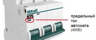
The first and most important thing is the current
. In order for the phase switch to fit your power supply system, the main criterion that you need to look at when choosing is the permissible current. You should not buy a device whose current exceeds the rated current of the input circuit breaker. Although the selectivity of protection should ensure a safe operating mode, it would not be superfluous to bring the electrical network into compliance with the permissible current and power.
The second parameter is the ability to adjust
. On cheap switches there is generally no way to set the minimum and maximum voltage in the power supply network at which switching occurs and the priority phase is selected. The minimum set of adjustments is to set the minimum voltage at which the devices can operate, or the maximum. In more advanced models, you can adjust the time after which you need to try to switch to the main phase and other settings.
The third parameter is the display and indication method
. Simpler models have LED indication, usually one LED per phase and an additional “EMERGENCY” indicator. When the line is normal and a load is connected to it, the corresponding LED lights up, for example, green; when the line is normal, but it is in reserve, the LED flickers; when there are problems on all lines, the “EMERGENCY” indicator lights up. More advanced models have a seven-segment indicator or LCD display. The purpose of the indicators is to display the voltage value, settings parameters, enabled and priority phase. The least visual indication method is individual LEDs, and the most obvious is an LCD display.
The fourth parameter is functionality
. The simplest PF has a set of preset parameters of the supply network, accepted as the norm, and strives to adhere to them. But each electrical appliance requires an individual approach to power supply, usually 220 +/- 10% V, and in some cases the tolerance can be increased, or vice versa - reduced. In more advanced models, these values are set by turning screws or knobs to the desired position, according to the graduation. The most functional are models with display and touch controls. At the same time, you should not assume that the simpler the worse; it is often not worth overpaying for functions that are not useful.
If the power of your switch is not enough to meet your needs, there are two ways to solve this problem:
- Buy a switch designed for higher current.
- Install the electromechanical switch so that the starter or contactor coil is connected to the output terminals of the phase switch. Thus, the entire load will fall on the power contacts of the latter.
How to make a switch break a phase and not zero
If you have an incorrect wiring diagram for connecting the switch to the lamp, and the zero opens instead of the phase (Click to find out how to determine which wire is the zero and which is the phase). This can be corrected only by changing the connection in the junction box.
To do this, you need to find a distribution box, which is most often located directly above the light switch, at a distance of 10-30cm from the ceiling. According to electrical installation rules, it must be easily accessible and you can often find it quite quickly (but, unfortunately, not always).
ATTENTION! All work to change the circuit breaker connection diagram must be carried out only on a de-energized network. To do this, be sure to turn off the circuit breaker of this group in the electrical panel, and then make sure there is no voltage at the installation site
So, this is what the connection diagram looks like in a distribution box, in which zero is connected to the switch, and the phase goes directly to the lamp.
Most often, the diagram will be exactly like this, the input power cable will enter the box and then go out to the next distribution box, so, usually, exactly four cables go in:
1.n – Cable going to the switch (two-wire for a single-key switch)
2.n – Electrical input cable (Standard three-wire: phase, neutral, ground)
3.n – Cable going to the chandelier (Three-core: phase, zero from the switch, grounding for a single-key switch)
4.n – Cable going to the next light switch or socket groups (Three-core: phase, neutral, ground)
Now we need to change this circuit so that the switch breaks the phase and not the zero.
For this:
— Wire 1.1 in the diagram, going to the switch, is connected to the contact of phase wires 2.2.+ 4.2
— Wire 1.2 (returning from the switch) is connected to phase wire 3.2 which goes to the chandelier
— The remaining neutral wire 3.1, going to the chandelier, is connected to the contact of conductors 2.1 + 4.1
The diagram for replacing the neutral conductor in the switch with a phase conductor is presented below:
Now your switch will be connected correctly, the phase conductor will approach it, and not the neutral one. As you can see, making changes to the connection diagram is quite simple.
UPD: Some advise simply changing the phase with zero in the electrical panel and automatically the circuit in the switches will change to the desired one. I would not advise everyone to do this, you first need to thoroughly analyze the entire electrical wiring diagram of the apartment, and this is quite difficult to do; it is better not to carry out such serious interventions without the proper experience and knowledge.
Uniqueness of use
There are times when connecting a three-phase electrical network must be done in a strict phase sequence. The whole problem is that there is no guarantee to correctly designate the side of rotation of the rotor during the process of connecting the motor to the network if the phasing stages are not checked.
During operation of the system mechanism, it is important to strictly observe the direction of rotation, because this is how the technological cycle is ensured. Therefore, the main point of stable operation is absolute adherence to the connection sequence.
In this case, the correct solution to the problem is to use a unique device - a phase indicator, which gives a clear understanding of the scope of its application.
For example, in the case when the wires supplying the windings have the correct connection order, then the operation of the motor rotor is determined by the conditional rotation in the direction of the arrow on the clock, but with the slightest change in the order of the phase sequence, the direction of rotation will be changed.
As a result, the technical process, where the main element is the engine, will be grossly changed with subsequent disruption, which will undoubtedly lead to stoppage and failure of the equipment. However, if the sequence of phases is changed in the correct alternation, the operating order of the engine will be restored to normal and the process will again become correct.
Danger and consequences of misalignment
What is the danger of phase imbalance in the electrical network? Conditionally negative aspects can be divided into three groups:
- Harm to electrical receivers (devices, equipment): damage to them, reduction in service life.
- Harm to electricity sources: mechanical damage, increased electricity consumption, reduced service life of the source.
- Consequences for consumers: increased electricity costs, need for electrical equipment repairs, possible injury.
Due to the fact that electricity is distributed unevenly across conductors, electricity consumption in the electrical network increases significantly. A three-phase network that has developed asymmetry can reduce the service life of electrical appliances and household appliances.
If this is an autonomous power plant, then the oil and fuel consumption in this situation increases significantly, and the generator may break down. When one phase receives more voltage than the other two, electrical safety is compromised. And this can lead to various electrical injuries, as well as fire of electrical household appliances and the wiring itself.
As you can see, the consequences of this phenomenon are significant and their solution and elimination can lead to large material costs. In order to avoid such an unpleasant situation, certain measures should be taken in advance.
Purpose of the phase switch
A phase switch is an electrical device designed to connect critical electricity consumers. Responsible consumers mean devices that must operate continuously 24 hours a day. For example, equipment for server rooms, automation of gas boilers or video surveillance systems at protected sites.
Connecting equipment via a phase switch
There are 2 main categories of phase switches:
- manual (mechanical);
- automatic.
The manual phase switch is a multi-position cam switch. It can be installed not only on a DIN rail, but also on the control cabinet door. In essence, this is a button that allows you to independently switch the consumer’s power supply from one line to another with the effort of your hand. Such devices are cheap and easy to understand. But they are not able to work without a person.
Manual modular switch
Automatic models do not require human presence. They have a microcontroller installed that monitors the input phase voltages. 4 wires are connected to the upper terminals of the device: 3 phases and zero. 2 wires are removed from below: 1 phase and zero.
During operation, the device connects one of the incoming phases (for example, L1) to the output terminal. If the voltage in phase L1 for some reason goes beyond the permissible limits, then phase L2 is connected to the output. If the voltage goes beyond the limits in L2, then L3 is connected.
Connection diagram
After purchasing, you may have difficulty with how to connect the phase switch. If you do not have experience working with electricity, it is better not to try, since you will have to work with high voltage in a three-phase network - 380 Volts. In addition, improper use and connection of such equipment can lead to a short circuit between phases.
The phase switch is a modular device that is installed in a panel on site on a DIN rail. A three-phase circuit breaker is installed in front of it. After installing the primary circuit, we move on to the output circuit. But how to connect the secondary circuits depends on the switch model. The connection diagram must be indicated in the technical data sheet or other similar documentation and may differ from manufacturer to manufacturer.
Finally, we recommend watching a video that explains in more detail what a phase switch is and how to connect it in the panel:
A phase switch is a low-cost method that will increase the stability of the power supply; this can be especially important outside the city in a cottage or holiday village, where there are usually power outages. We talked about how to connect and where to install, as well as all the parameters of such devices. The choice of uninterrupted supply is yours based on your needs and budget.
Device Features
The PEF-301 electrical switch selects the optimal phase depending on the quality of the voltage in the network. Direct power supply from the device is provided with a load power of up to 3.5 kW (16 A). If the load power exceeds 3.5 kW, the device controls the coils of magnetic starters.
Voltage quality parameters (minimum and maximum values) are set by the User. There are special controls on the front panel of the case for this purpose.
Advantages of this type of power switching device:
fixed delay of 12 seconds to avoid false transition to the reserve phase during the period when the network voltage drops below a specified minimum value;
the possibility of eliminating a return to the priority phase when the device is used to power small-power consumers where frequent switching is not desirable;
The device design allows you to avoid phase-to-phase short circuits due to contact sticking thanks to a special circuit for connecting three built-in relays.
The electronic phase switch PEF-319, unlike the previous model of the device, supplies power to the load at a load power of up to 6.6 kW (30 A). If the load power exceeds 6.6 kW, the device controls the coils of magnetic starters.
In general, load transfer switches are similar in operating parameters.
The key features of the PFE-319 device are:
the ability to switch to the priority phase from the backup one, after restoring the parameters of the priority phase, after a return time specified by the User - from 5 to 200 s;
the presence of a digital indicator that displays the voltage value of the phase from which the load is powered. When the load is disconnected, the digital indicator displays the voltage value of the phase closest in voltage to the set voltage range;
the glow of one of the green LEDs on the front panel of the device indicates the phase to which the load is connected, as well as the blinking of the red LED to monitor an emergency situation.
If the voltage on all three phases does not meet the specified quality parameters, the load is switched off. After the voltage parameters on one of the phases are restored within acceptable limits, the phase switching device will connect the load to this phase.
Basic functions of switches
The main purpose of electronic phase switches is to timely and automatically transfer power from an overloaded line to a freer one. Very often, this need is associated with voltage drops during which devices and equipment cannot function normally.
Most appliances, household appliances and other devices have individual technical characteristics that ensure their normal operation. This data is indicated in the product data sheets or operating manuals. First of all, the values of the minimum and maximum voltage are displayed at which the device can operate normally, and the wiring will not be destroyed under the influence of loads.
Combating overloads is of great importance, so every automatic phase switch is configured for this. To ensure the correct response of the device, the response time must be set correctly. That is, the indicators are set in such a way as to exclude false alarms.
Standard phase switches allow adjustment of the most important parameters. First of all, the minimum and maximum voltage limits are set. In this case, it is necessary to exclude the intersection of the values of the upper and lower areas, which can lead to unstable operation of the switch. It is recommended to set the upper and lower limits not by eye, but in accordance with the instructions and technical specifications of the equipment.
An important setting is the reset time, during which the switch attempts to return to its original position by resetting the contacts to the original power source. However, this will be possible only if the voltage on this line returns to normal.
Another setting is the turn-on time, where you set a certain amount of time after which the switch must attempt to turn on power after no power has been received. That is, after power appears on at least one line, the backup power source can be turned off.
There are other settings that can be used in various combinations. It all depends on the design, purpose and capabilities of the specific switching device.
Necessity of application
There are situations during which the connection of a three-phase network must be carried out in phase rotation order. The fact is that the direction in which the rotor rotates when connecting an asynchronous motor to the network cannot be accurately indicated unless we strictly follow the phasing procedure.
For example, when it comes to operating a fan for the corresponding system or a drive for operating a pump, it is necessary to clearly know the direction of rotation. This ensures the execution of the technological cycle. Therefore, it is important to maintain consistent connections in this case. In order to solve this problem, you should resort to using a special device called a phase indicator. This allows you to understand why it is needed. The scope of application of the phase indicator is quite wide and is constantly growing.
If the phasing is set correctly, then the order of the phases goes from A to B and ends with C. The same order determines the direction of rotation of the engine. For example, if the wires that power the windings are connected in the correct order, then the motor rotor operates conditionally in a clockwise direction. However, in a situation where two of these phases are changed, the direction of rotation of the rotor will be disrupted. Then the technological process in which the engine is involved will simply be disrupted. This will cause the equipment used in the drive to be damaged and fail. After this, if you perform the reverse procedure with the phases, the engine operating order will return to normal and the process will be correct.
Purpose and functions
This technology is used in a network of three-phase loads. It is most in demand for protecting synchronous or asynchronous electric motors, high-precision three-phase machine tools, high-tech electronics, and pumps. Please note that incorrect phase rotation will lead to low efficiency, overheating and reduced insulation levels, which can lead to breakdown.
Used for the following purposes:
- For switching converter equipment for which compliance with the phase sequence is important: power supplies, rectifiers, inverters and generators;
- For ATS systems (putting into operation backup power sources) or connecting an emergency lighting system;
- For special equipment - machine tools, crane installations, the power of which is no more than 100 kW;
- For electric drives of three-phase motors with a power of no more than 75 kW.
This device is not used for switching single-phase loads.
In general, the phase control relay is used for various industrial and household equipment and is a mandatory fuse for those control circuits that require constant monitoring of voltage levels and other parameters of external lines.
In three-phase networks it controls:
- voltage level, implemented, in the overwhelming majority, for equipment of this class in cases where its value goes beyond the established limits;
- phase rotation - will perform switching in the event of emergency phase sticking or if they are incorrectly located relative to the equipment supply inputs;
- phase loss – disconnects the consumer in the event of a phase loss and subsequent lack of voltage;
- phase imbalance - performs switching in the event of a change in phase or line voltage in relation to the rated value.
Advantages of phase control relays
Compared to other emergency shutdown devices, these electronic relays have a number of significant advantages:
- in comparison with the voltage control relay, it does not depend on the influence of the EMF of the supply network, since its operation is adjusted to the current;
- allows you to detect abnormal surges not only in a three-phase power supply network, but also on the load side, which allows you to expand the range of protected components;
- unlike relays that operate to change the current in electric motors, this equipment also allows you to record the voltage parameter, providing control over several parameters;
- is able to determine the imbalance of supply voltage levels due to uneven loading of individual lines, which can lead to overheating of the motor and a decrease in insulation parameters;
- does not require the formation of additional transformation from the operating voltage.
Unlike relays operating only on voltage, it provides effective protection against regenerated voltage generated by back EMF. In the event that one of the phase voltages disappears, the engine continues to gain a sufficient level of energy from the remaining two. In this case, in the de-energized phase, an EMF will be generated from the rotation of the rotor, which continues to rotate from two phases in emergency mode.
Due to the fact that the contactors of electric motors do not open from the relay during such operation, there is a risk of damage to the electrical machine with its further breakdown. The monitoring relay, in turn, is capable of detecting a phase angle shift, thereby providing full protection.
This function is especially relevant when the operating mode of the engine, in the event of its reverse rotation, can damage the rotated element or injure a worker. As a rule, this situation arises when changes are made during the de-energization of an electrical machine, changing phase loads, phase rotation order, and others.
Device settings
Simple models have a minimal set of settings. They are not adjustable by the buyer. The algorithm for their operation is established by the manufacturer and cannot be changed. Complex, expensive models, on the contrary, have many customizable parameters.
Lower voltage limit
This parameter determines at what input voltage the switch to the spare phase will occur. For example, if the voltage in phase A is more than 180 V, then the consumer is connected to phase A. If it is less, then a transition to phase B occurs.
In simple switch models, the default value is 180 V. In more serious models, it can be adjusted, and the minimum voltage limit can be set to 120-200 V.
Setting up the device is usually done using adjusters for a Phillips screwdriver. They are easy enough to twist. Hence the popular name for such regulators is “twist”. Other switch patterns use buttons. There is no fundamental difference in the operation of these regulators. Therefore, the choice is a matter of ease of use.
Upper voltage limit
Setting the upper voltage limit is necessary for the same task as setting the lower limit. But in the case of an upper limit, consumers are protected from overvoltage.
If the voltage in the current phase becomes more than permissible, the device automatically switches to another phase. For example, if the voltage in phase A exceeds 250 V, the APF will switch to phase B with a normal voltage of 230 V.
Return time
The return time to the priority (main) phase can also be adjusted using knobs or buttons. This parameter determines how many seconds after normalization of the voltage in the main phase the AF will return to it again.
For example, in the network, for some reason, there is a long-term voltage drop in one of the phases. APF goes to spare. After some time, the voltage in the main phase takes on an acceptable value. But the switching device waits. And only after the return time does it return to the normalized main phase.
The reset time is necessary to avoid constant false switching of the device. This increases the service life of the internal relays and reduces the risk of damage to the load.
This setting varies greatly depending on the type of consumer. For example, for refrigerators it is recommended to set the return time to about 3-10 minutes. For incandescent lamps 1-2 minutes is enough.
Design and operating principle
Structurally, the device includes input and output contacts, indicators of normal power supply and emergency, regulators, indicated in the diagram by the corresponding numbers (Figure 1):
- Emergency indicator;
- Indicator of connected load power supply;
- Potentiometer allowing you to select the desired mode;
- Asymmetry level regulator;
- Voltage reduction regulator;
- Potentiometer that allows you to adjust the time setting.
Not all models provide the full range of settings for the above parameters. They depend on the purpose of the specific relay and the scope of application.
Rice. 2. Schematic diagram of operation
In normal mode, voltage is supplied to the power circuit from the EMF source E1 (Figure 2) to the consumer, be it an engine, a machine tool or other equipment. The phase control relay R is connected to the tap through the corresponding terminals, designated in the diagram as L1, L2, L3 and the neutral wire N. A logical circuit on transistors is assembled inside the device, which sends a signal from the output contacts to break the starter coil P to turn off. If necessary, the shutdown signal can be configured to both de-energize the consumer and disconnect the external electrical network.
In the event of an emergency - loss of one of the phases, short circuit, sharp increase in currents, the harmonic component of the electrical parameters of the network changes. To which the protection device reacts and sends a corresponding shutdown signal through the power circuits through terminals 24 and 21 to the contactor coil.
After the activation of power contacts in the practice of power supply to consumers, a natural restoration of the parameters of the supply network can occur, during which phase alignment will occur. In this case, the relay will return the contacts to the on position, due to which the automatic reclosure system is implemented and the voltage supply to the windings of the motor or other consumer will be resumed.
Using the “Start” and “Stop” buttons, you can manually control the power of an electrical device.