Let's try again to embrace the immensity in one post? This time the story will be about RCD.
This post has a video version for those who like to listen and watch:
Now, in the 21st century, electricity is available in almost every home. And almost every citizen knows that electricity can kill. The news that someone has been electrocuted somewhere is already commonplace for us, and the media writes about it only if the case is special - either a famous person was killed, or the carelessness is absolutely blatant. But in the late 19th and early 20th centuries, every death from electric shock was the center of attention: electricity was a novelty. Here are a few notes that caught my eye:
Thousands of cases where someone was electrocuted have been analyzed, allowing engineers to figure out some patterns and take action. Namely:
It turned out that there are almost no cases of death when a person died from communicating with voltages less than 50V. Low voltage (with a bunch of reservations) is quite safe. Who licked the crown as a child to determine the charge?) The use of low voltage (12V, 24V, 36V, etc.), although it provides almost complete safety, for example in a swimming pool, is not suitable for general use. If we lived in an alternative universe, where instead of 230V in houses there is only 12V, then the kettle would consume not 16A of current, but almost 300A, and would be connected to the outlet with a thick cable. And all because when the voltage decreases, you will have to increase the current so that the power of the device remains the same. And high current requires thick cables.
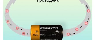
Second important observation. Current flows in a closed circuit , if the Earth is part of this circuit, then a person is always in danger. But if a person is connected to different circuits isolated from each other, for example, if you touch one generator isolated from the ground with one hand, and another isolated generator with the other, then nothing will happen. The circuit is not closed - no current flows. This is how galvanic isolation and isolation transformers appeared. I’m not old enough to see this in person, but I have seen references to the fact that an isolation transformer was installed in houses with an outlet in the bathroom, with the caption “for an electric razor.” A 220V electric razor plugged into this outlet could be used safely; touching a live conductor, even while standing in a grounded bathroom, could not kill. True, a small transformer could only handle a few tens of watts of load power; plugging a hair dryer or heater into such an outlet would simply burn it out. Therefore, the method did not take root in everyday life; you don’t have a separate room for a galvanic isolation transformer?)
And finally, having averaged individual characteristics, we compiled this graph of the dependence of the current strength, exposure time and consequences for a person. May the authors forgive me, I simplified it a little for understanding:
UPD: picture corrected
It turned out that it is not the voltage itself that kills, but the current flowing through the body. At currents less than 0.5 mA (light green area), a person does not feel anything. At currents of 0.5-20 mA (dark green area), the current already stings and bites unpleasantly. At currents of 20-100 mA (yellow area) it actually shakes, cramps the muscles (you can’t pull your hand away) and causes pain. At currents of more than 100 mA, some may already die. From the graph you can understand where the value of 30 mA came from (green line) - with currents less than that, a person is unlikely to die and can take action himself if he feels that he is being shocked. But when there is more current, you need to urgently save him, otherwise he will die.
Protection is still needed
The use of low voltage or the use of galvanic isolation is not a very convenient way to protect people, therefore they are used only in narrow areas, where there is no other way. But how can we protect people from electric shock without significantly changing the existing electrical networks? The idea is simple and ingenious - you need to analyze the differential current.
Differential current is the difference in current between two conductors, for example between the phase one going into the load and the zero one returning from the load. The appearance of a noticeable differential current in a circuit is most often abnormal, and it is better to turn off the circuit; what if the current flows into the ground through a person? It's like comparing the coolant flow into and out of a heating battery. If 100 l/min goes into the battery and 100 l/min returns, then the system is sealed. If 100 l/min is supplied to the battery, but for some reason only 98 l/min is returned, then 2 liters leak out somewhere!
In an ideal world, it is enough for us to install a device that controls the very fact of the appearance of differential current. If everything is in order, then there is no differential current. If the current appears, we turn off the load. But in the real world, unfortunately, differential current (leakage current) appears in devices even if everything is working properly, so you have to make a compromise and choose a certain threshold value of the differential current, the excess of which will cause a shutdown.
Let's put ourselves in the shoes of engineers at the beginning of the 20th century and try to invent a device for detecting differential current. We need to detect the occurrence of a leak of 30 mA, since with smaller leaks, even if it passes through a person, there is no particular danger to life.
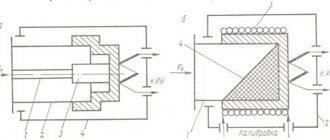
The first design - two identical electromagnets, opposite each other, are engaged in pulling the armature. The current flowing into and out of the load, flowing through the windings, creates a magnetic field, the stronger the greater the current. If there are no leaks in the circuit, then the currents through the electromagnets are equal, they develop the same magnetic field and the armature stands still. If we have a leak in the circuit, then the current through one of the electromagnets will be less (load current - leakage current) than through the second (load current), the armature will be pulled and open the contacts.
Theoretically, the scheme is working, but it is too capricious - it required very precise manufacturing of electromagnets and fine-tuning of the mechanics. Therefore, engineers began to think about how to get rid of unnecessary mechanics. This is how we came to a modern circuit with a transformer:
On a closed magnetic circuit, two windings are made, connected in antiphase, and a third winding to drive the solenoid. If the currents through the first and second windings are equal, then the magnetic fields are equal, and since they are directed towards each other, then the total magnetic flux through the third winding will be zero. If there is a leak, the currents become unequal, and a magnetic field proportional to this difference will begin to circulate through the third winding. And where there is an alternating magnetic field, there is induction and a current is excited. If it is enough to trigger the solenoid, the armature will release the latch and turn off the circuit.
A device ingenious in its simplicity and reliability. True, it didn’t turn out to be cheap - the mechanics still turned out to be delicate and capricious, is it a joke - to detect a 30 mA difference at a rated current of 16A is like hearing the squeak of a mouse against the background of the roar of a train. This is what an electromechanical RCD looks like:
Then they made a modernization - they threw out the delicate, expensive and oversized mechanics and installed an electronic amplifier, the current from the winding of the differential transformer is amplified by a special microcircuit, and this already supplies voltage to the opening solenoid. Such RCDs turned out to be more compact and much cheaper.
And now attention, an important point, what will happen if there is a short circuit in the load? Nothing! Since there is no condition for triggering, there is no difference in currents at the input to the RCD and at the output from the RCD. The wires will become red-hot, the insulation will drain onto the floor, and the RCD will not turn off because it does not have overcurrent protection. Therefore, an RCD without built-in overcurrent protection ALWAYS used in conjunction with a circuit breaker or a fuse. By crossing RCDs and circuit breakers, manufacturers have developed a hybrid - RCBO (residual current circuit breaker), which is more often called a diffavtomat in jargon; such a device is self-sufficient and does not require an additional circuit breaker.
The invented RCD worked perfectly, if not for the proliferation of semiconductor devices. Many devices began to transform the voltage and type of current within themselves - making direct current from alternating current, then alternating current again, sometimes of a different frequency or magnitude. Because of this, all sorts of unpleasant features became possible, for example, if one of the lines with direct current in the device is shorted to the housing, then the leakage current will be pulsating - only positive half-waves of current will go to the ground. A conventional RCD may not work in such cases. For such cases, special RCDs have been developed that are designed to operate not only with a sinusoidal leakage current, but also with a constant pulsating leakage current and called them type A. And the old RCDs, which operate only on alternating current, were called the AC type . And for very unpleasant cases (for example, breakdown of circuits after power switches in converters with high conversion frequencies) they came up with type B. The difference between types of RCDs is most clearly demonstrated by this picture from German Wikipedia:
To ensure selectivity, when connecting RCDs in series, special selective options have been created, often with the designation S or G in the name. They have a built-in delay of several tens to hundreds of milliseconds. So, if there is a selective RCD at the entrance to the house, and a non-selective RCD on the floor panel, then when the voltage is shorted to the body of the washing machine, the non-selective RCD on the floor will first trip, while the selective one gives a delay. If at the end of the delay the differential current does not disappear, the selective RCD will trip. I wrote about selectivity in a post about fuses (LINK). The selectivity does not depend on the rated threshold differential current, that is, in the event of a breakdown on the housing, both a 30 mA RCD and a 100 mA RCD will operate immediately, which is why I had to tinker with the delay.
And now that it has become clear HOW the RCD works, it’s time to talk about grounding, will the RCD work if there is no grounding contact in the sockets? Will! The only difference is that if the washing machine has a breakdown on the housing in a grounded network, the RCD will turn off immediately, since the differential current will be huge (it will go from the housing to the grounding conductor). But if there is no grounding in the network, the washing machine will stand like a guerrilla in the bushes with a voltage of 230V on the body, and the RCD will turn off only when the current flows through a person. That is, the presence of grounding increases safety, but is not a prerequisite for the operation of the RCD.
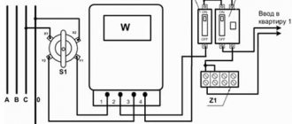
How to properly connect residual current devices
When connecting leakage current protection devices, several basic rules must be observed.
First and most important. RCDs and automatic devices must be operated in networks with a solidly grounded neutral with a separate grounding wire (three-wire or five-wire system)
In this case, the housings of all electrical receivers protected by devices from leakage currents must be reliably grounded. Grounding can be carried out through the socket contacts or with a separate bolt-on wire.
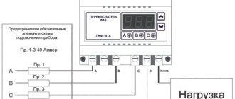
Second. It is necessary to ensure that the wires are connected correctly. Zero should be connected to the terminals marked with the letter “N”, and phases to the phase terminals. This rule, which at first glance is not obvious, is associated with connecting the test button and the electronic protection circuit.
Third. Conductors of the same name protected by different RCDs cannot be connected to each other. This mistake is often made by inexperienced electricians when they use a common zero for several socket blocks. Such a connection, when connecting a load, immediately triggers the protection.
Let's return to the real world. Why there may be false positives
One of the reasons why old-school electricians do not accept RCDs is false alarms. And false alarms (provided that the device is working properly) can only happen for one reason - there is a leak, and it is noticeable. But the reasons for the appearance of leaks are varied:
- Insulation may be broken. If the cable is old and exposed to the sun, then cracks may appear in the insulation. We get it a little wet and we have an unpredictable amount of leakage.
- Normal leak in equipment. Even in working equipment there is a certain amount of leakage, and with alternating current direct contact is not needed, it is enough that one of the conductors made a long loop along the body. The resulting capacitive coupling is sufficient for a small current to flow. A special device can be used to measure the amount of actual leakage in the line with all connected devices. If direct measurement is not available, you can use the rule of thumb (7.1.83 PUE) - assume that for every 1 A of current consumption by the device there will be 0.4 mA of leakage, as well as 10 μA of leakage for each meter of phase conductor length. (The numbers are very average, like the average temperature in a hospital, but at least it’s something). It is desirable that the sum of all leaks in the circuit during normal operation does not exceed 1/3 of the rated value of the disconnecting differential current. Well, as a cherry on the cake - if the RCD says that the differential tripping current is 30 mA, this means that at 30 mA it will definitely turn off. And it definitely won’t turn off at half this current - 15 mA. But with a differential current between these values - depending on your luck. If you have a 30 mA RCD, and a bunch of devices are plugged into sockets, so that the total leakage during normal operation is 20 mA, then a situation is created where the RCD can spontaneously turn off for no apparent reason.
- There is an installation error, and somewhere (for example, in one of the socket boxes) there is a connection between the working neutral conductor N and the grounding conductor PE, or they are mixed up.
Classification of RCD devices
Let's look at the important characteristics of these devices. Residual current devices are classified into the following types according to their operating principle:
- AC type - used to protect household electrical appliances from current that increases slowly or occurs intermittently. This type of RCD is triggered by alternating current.
- Type A, responds to pulsating direct current, which can increase in steps. Automatic devices of this type are most often installed in apartments and houses for separate protection of household appliances, such as dishwashers, washing machines, and televisions. Type A RCDs are more expensive due to their complexity.
- Type B - used in industrial enterprises, not used for installation in apartments.
- Type S and G - these RCDs are selective, that is, they are triggered after a few seconds of leakage. It makes sense to install these devices if several devices are installed in the line.
The RCD is also divided into groups according to the number of poles:
- bipolar;
- four-pole.
Two-pole RCDs are intended for operation in single-phase electrical networks. They occupy two spaces in standard electrical panels according to the DIN standard (0.35 cm). Four-pole RCDs operate in three-phase networks and occupy 4 spaces according to the DIN standard (0.7 cm).
Two-pole and four-pole RCD
According to the type of design, RCDs are divided into:
- Electromechanical.
Electromechanical devices operate immediately when there is a current leak, regardless of the network voltage. This device does not require an external power source to operate. They do not have electronic components that can be damaged by power surges.
Electronic.
Electronic RCDs have finer mechanics than electromechanical ones. The current measurement mechanism operates regardless of voltage loss in the network, since the transformer reacts only to the difference in current. We can say that for this type of RCD to operate, it requires mains voltage and current leakage, unlike the electromechanical type of device.
Fire protection RCDs? They are all fireproof!
If you open the manufacturers' catalog, you will notice that RCDs are produced for different differential currents. If the reason for choosing a current of 30 mA is clear, with 10 mA you can also guess in principle (even more sensitive devices for more sensitive protection), then why are devices with a current of 100 mA and even 300 mA needed? A person will die with such currents!
Such RCDs are often called “fire protection”, since due to the large differential current they provide little protection to a person from electric shock, but still perform the function of protection in the event of insulation damage. If the insulation is broken and an electric arc ignites upon contact with another conductor, the insulation will begin to char and generate heat, which can ignite flammable materials around it. If you are lucky and the current in the arc is small, the circuit breaker will not trip. But the heat generation and temperature can be sufficient to cause a fire. Of course, then the fire will break the insulation, a short circuit will occur and the circuit breaker will trip, but this will not extinguish the fire.
How to distinguish an electronic RCD from an electromechanical one
The difference in design of these devices does not affect performance. These differential protection switches cope with their functions quite successfully and have high parameters. Let's consider the design of an electronic and electromechanical device.
The electromechanical protection option has a toroidal differential transformer, a polarized relay and a trigger mechanism. A differential transformer captures the difference in current between the phase and neutral wires, amplifies it with a secondary step-up winding of the transformer, and the amplified differential signal is fed to a polarized relay.
It works and turns on the protection trigger. Electronic protection also has a differential transformer, a polarized relay, but the size of the transformer is smaller, since the signal is amplified by an electronic board that is powered by mains voltage and supplies a signal to a polarized relay, which is also connected to the trigger mechanism. Electronic protection only works when mains voltage is present. But our network has not yet reached good quality.
The design of the electronic RCD contains an electronic amplifier A, operating from the mains voltage (right)
Network outages, voltage drops or increases, impulse noise, and sudden voltage surges are not uncommon. The electronic filling of the protection may not withstand such tests and fail. Another option when electronic protection cannot perform its functions is the neutral wire burns out or breaks (relevant for old electrical wiring).
The neutral wire may burn out in your electrical panel at the entrance, and since the electronic protection device operates on mains voltage, the protection will be disabled. You will be deprived of protection against current leakage of the remaining phase voltage. Therefore, for the electronic version of the switch, you need to frequently check its operation by pressing the “TEST” button. The mechanical version of protection is not afraid of lack of voltage and zero break. Therefore, their reliability will be higher than electronic switches.
Let there be srach!
A separate discipline of debate is which RCD is better, electromechanical or electronic. An electromechanical RCD uses differential current energy to turn off, so it can operate if the neutral conductor breaks, and in general it does not contain delicate electronics, but contains delicate mechanics. An electronic RCD requires power to operate the electronic amplifier, so if the zero is broken, it stops working, often without disconnecting the circuit. Each configuration has its own advantages and disadvantages. And to protect against zero loss, I strongly recommend installing a voltage control relay.
But since most readers expect a specific answer from me, I will say that this is not important. There are standard requirements, there are required characteristics, and in the end there is a competitive price. Therefore, the manufacturer gives exactly what is required of him, but how the desired is obtained is not so important. And if the manufacturer is a handyman, then the absence of electronics does not automatically mean that the product will be suitable. In addition, no manufacturer has been able to produce a type B RCD without adding electronics.
To monitor the serviceability of the RCD, there is a “test” button on the front panel, which, by closing the circuit with a resistor, simulates the appearance of a differential current. If the RCD turns off when you press the test button, then it is working properly. Manufacturers recommend checking the serviceability of the RCD monthly (what optimists!), or, realistically, I’m talking about testing once every six months.
RCD selection criteria
Above we looked at what types and types of RCDs there are, and we were convinced of the need to use them. To the question of which RCD to choose for your home and how to choose this really necessary device, specialists can best answer. When building a new house or during a major renovation of an apartment, it is necessary to develop a design for the entire electrical supply of the premises. During the repair process, many technical nuances arise that only experienced electrical engineers can handle. They will help you choose the right residual current device for your home.
If your apartment does not have a voltage relay installed, then you may be susceptible to power surges. Instead of 220 Volts, 300 Volts may suddenly appear in the outlet. Such voltage surges are very dangerous for electronic RCDs. Indeed, due to such jumps, its electronic board may fail. You may not even know that the internal device has failed. Therefore, it is especially recommended to periodically check the functionality of the RCD. To do this, there is a “Test” function on the device; it is better to do this once a month.
RCDs from various manufacturers
It also doesn’t hurt to pay attention to the choice of RCD manufacturer. Let's look at the best European manufacturers of these devices:
- ABB;
- Legrand;
- Siemens;
- Schneider electric;
- Moeller;
- A.E.G.
But there is already a quite decent alternative among domestic manufacturers:
- DEKraft;
- KEAZ;
- IEK;
- Contactor.
Based on this rating, you can study the reviews on various sites yourself to decide on the manufacturer of the automatic machine for your home.
The choice also depends on where you will install this device - in a private house or apartment. The voltage, length and number of connected household appliances require special attention when connecting an RCD.
Important! The RCD will protect the electrical circuit only from current leakage, but will not protect from network overload and short circuit currents. Therefore, a circuit breaker should be installed together with the RCD.
When you can't trust anyone
Manufacturers of some devices cannot rely that the buyer is adequate and there is protection in his electrical panel, so they add their own.
In the form of a personal RCD for a device in a plug or in the form of a box on a cord. If the buyer connects the boiler with plastic pipes and does not ground the housing, then if the heating element loses its tightness, electricity will flow through the water in the pipes through the person into the grounded bath. This RCD protects one device in particular, and in some countries there are regulations that require the addition of RCDs to certain types of devices. As you can see, the device also contains a “test” button to check the functionality of the protection.
RCD connection diagram in an apartment
Electricians advise installing RCDs only on equipment that requires compliance with increased safety standards, for example - a washing machine, boiler, electric stove, microwave oven. There is no need to connect the lighting in the apartment through an RCD, since if conventional lamps burn out, there will be a power outage in the entire apartment.
Attention! The most convenient place to locate an RCD in an apartment is a place next to the power source. Usually it is installed next to the meter, in the electrical panel at the entrance to the premises.
Let's consider how this device can be connected to an apartment.
The RCD connection is carried out according to two common schemes - TN-C and TN-CS:
- TN-C system.
- TN-CS system.
TN-C circuit
The most popular, consisting of one common conductor acting as grounding and one working neutral conductor. This scheme is one of the most reliable.
This circuit includes a neutral and grounding wire, combined into one common conductor, which is divided after entering the room into two conductors N (zero) and PE (grounding). This option is less common in our housing construction.
TN-CS circuit
RCD or diffavtomat? (VDT or RCBO?)
Manufacturers, with care for us, combined two devices in one housing - an RCD for protection against electric shock and a circuit breaker for protection against overcurrent, calling it RCBO - Automatic Residual Current Switch. Sellers are more likely to respond to the slang name “diffavtomat”. There are not many advantages of such a hybrid - it is compact, and it is intuitive (one lever, not two). But there are some disadvantages:
- It deprives designers of flexibility, for example, to install one RCD and several automatic devices, or vice versa, several RCDs and one automatic device.
- It complicates troubleshooting, since there is usually no indication and it is difficult to understand why it turned off (options: thermal release, electromagnetic release or residual current electromagnet tripped)
- Cramming multiple devices into a compact package always forces developers to make compromises.
In my personal opinion, the use of RCBOs is justified only when upgrading the electrical panel, when there is no space inside, and the diff. I want protection. Then you can remove the circuit breakers one module wide and plug in the RCBOs one module wide and reconnect the wires. In this case, there is no need to expand the shield. In other cases, in my opinion, the combination of RCD + circuit breaker is preferable.
The feasibility of using RCDs
Let's consider why you need to use an RCD and from what negative impact factors the device provides protection.
First of all, a phase short circuit to the electrical equipment housing. Mainly, problem areas include heating elements of heaters and washing machines. It is worth noting that breakdown occurs only when the heat-generating part is heated under the influence of current.
Also if the wires are connected incorrectly. For example, if twists without a terminal box are used, which are subsequently recessed into the wall and covered with a layer of plaster. Since the surface has high humidity, this twist will be a breakdown that will leak into the wall.
The differential protection mechanism in this case will constantly de-energize the line until the area is completely dry or until the connecting node is redone.
Automatic protection is effectively used in everyday life: in electrical groups for the bathroom, kitchen and sockets, with a large number of powered devices. The ideal option is when this type of device is installed on each group of sockets
The scope of application of survey devices is quite diverse - from public buildings to large-scale enterprises. They complete electrical structures and circuits intended for reception and distribution: switchboards in residential buildings, current supply systems for individual consumption, etc. The main thing in this case is to choose the right RCD according to power.
I died. Why didn’t the RCD save you?
RCD is not a panacea, but nothing better has yet been invented. If you hold the phase conductor with one hand and the neutral conductor with the other hand, then for the electrical network you will be just another heater, the differential current will not appear and the RCD will not work. Also, if you put your finger into the lamp socket, current will flow through the finger, but there will be no leakage into the ground, and the RCD will not turn off. Therefore, even the presence of such protection does not mean that you can lose vigilance and caution. An experienced electrician doesn’t even grab his wife’s two breasts at the same time
Electromechanical UDT device
Electromechanical RCDs consist of the following main parts:
- housings;
- contact system consisting of terminals to which power wires are connected, moving and fixed contacts used for switching;
- instrument transformer and rectifier;
- polarized relay;
- mechanical shutdown systems (release);
- electric arc extinguishing systems;
- test button and resistor.
Polarized relay
The executive element in electromechanical differential current devices is a polarized relay. A polarized relay belongs to the class of bistable DC relays. It can be either in the off or on state in the absence of voltage on its winding. In the RCD, the winding of the polarized relay receives rectified voltage from the measuring transformer. When the threshold value is reached, the relay switches, which is mechanically connected to the release. As a result, the UDT is turned off.
TEST button
Unlike circuit breakers and other protective devices, RCDs have the ability to check the functionality of the device. The test is performed by pressing the “Test” button. This button, together with a specially selected resistor, forms a chain that simulates the occurrence of leakage current. The ends of the chain are connected to the neutral and phase wires. The string conductors do not pass through the ring core of the differential transformer. Therefore, during the test, the balance of magnetic fluxes in the measuring system is disrupted. The resistor value is chosen so that the artificial leakage current is equal to the rated operating current of the differential protection.
Summary
- The RCD serves to protect a person from electric shock and will turn off at life-threatening leakage current values. With small but harmless currents you will be shocked by electricity.
- The RCD works regardless of the presence of grounding, the only difference being that without grounding, in the event of a breakdown on the body, the RCD will turn off only when the current from the body can flow into the ground through you.
- An RCD is not a panacea, and you can kill yourself by picking up the phase and neutral wires. But they still haven’t come up with better protection options than RCD.
- Electromechanical or electronic RCD - it doesn’t matter. But it is important to regularly check the serviceability by pressing the “test” button. It is also highly advisable to use a voltage control relay.
- In the real world, healthy wiring and devices have leakage current that can cause a false tripping of the RCD. If the RCD trips for no apparent reason, deal with the leakage currents.
Actions when knocking out an RCD
If your device shuts down for no apparent reason, do a quick test before calling an electrician . Since faulty household appliances sometimes give this result, they need to be repaired or replaced, not the RCD. If the protective device does not turn on, disconnect all electrical consumers from the power supply - microwave, kettle, coffee maker, lighting fixtures, etc. Then restart the RCD: if it is connected, then use the elimination method to determine the faulty electrical appliance.
If the protective device is knocked out only periodically, correlate this with the switching on of a specific consumer. Make sure the result is correct by checking the electrical appliance by turning it on several times (if each time the RCD turns off the electricity, the problem lies in a specific household appliance). If such a test does not help, then the protective device itself or the wiring may be faulty, then you should immediately call an electrician.
Type of residual current RCD
If there is a leak in the electrical wiring or heater, the current will be variable, just like in the power supply. But leaks that occur inside electrical appliances will not always have only a variable component. If they contain semiconductor devices, the AC RCD may not respond.
| RCD type symbol | Designation on the body | What current does it react to? | Recommendations for use | Examples |
| AC | variable | To protect devices that do not contain semiconductor components | Heaters, AC motors, electric stoves | |
| A | variable and constant pulsating | To protect devices with electronic power supplies and control devices | Washing machines, office equipment | |
| IN | variable and constant | For industrial applications | Consumers in DC circuits |
Three-phase RCD device
Now let's talk in detail about the design of a three-phase RCD. As already mentioned, in a three-phase network there are three phase conductors and one neutral.
The voltage between any phase and zero is 220 volts, as expected, and the voltage between phases is 380 volts.
The main component of the residual current device is the differential transformer. This is an ordinary magnetic circuit made of ferromagnetic material with a winding. In addition to the differential transformer, the RCD contains the following components:
- 1. Housing
- 2. Power contacts (moving and fixed)
- 3. Independent clutch mechanism
- 4. Power wires
- 5. Trip relay
- 6. “Test” button
Now let's find out what's going on. All three-phase power wires, including the neutral wire, pass through the EMF coil, which is part of the transformer of the residual current device. Since during normal consumption of the device the total currents of all 4 wires are equal to zero, no EMF occurs in the coil.
If a current leak occurs along any of the wires, an imbalance occurs, and, as a result, the transformer core becomes magnetized. All this leads to the generation of current in the transformer winding. If the value of this current exceeds the RCD response current, the automation turns off the power.
External difference between electronic and electromechanical RCDs
On the body of the differential switch there are markings and a circuit diagram for switching on this type of device. On the displayed diagram of the electromechanical device you can see a differential transformer, its secondary winding with a connected polarized relay and a dotted line showing the connection of the relay with the trigger mechanism.
Diagram of an electromagnetic RCD (left) and electronic (right)
A “TEST” button with a resistor is also indicated. In the electronic form of the device on the case, you will find the difference in the circuit in the additional triangle with the designation A of the electronic amplifier between the transformer and the polarized relay and the connection of this triangle with the power wires, phase and zero.
What is an RCD and a differential circuit breaker?
In order to understand the protection devices once and for all, you should list all possible emergency situations that may occur during the operation of the electrical network. If you do not take into account relatively harmless troubles like power surges, then this list will not be so long:
- Overload.
- Short circuit (SC): both of these phenomena are accompanied by the flow of current with greater strength than the wiring can withstand (in the second case, the current is called ultra-high current). Excessive heat causes the wires to burn out. To protect against such troubles, fuses were previously used - fusible jumpers, which, if the current exceeded the current, burned out first, thus turning off the protected circuit. Today, instead of them, automatic switches (VA) are used, which have electromagnetic and thermal releases. When current flows in excess of the rated value, this mechanism disconnects the circuit, but after eliminating the fault, it can be switched back to the “on” position.
- A person or animal was struck by an electric shock either directly (touching live parts directly) or indirectly (touching a housing that was energized due to an insulation breakdown).
- Electrical contact between a conductor and any grounded conductive (metal) element resulting from an insulation failure. In this case, the “grounded element” means not only the equipment housing connected to the ground loop, but also, for example, a metal box or building structure. Current flows through the electrical contact, causing heat to be generated. This may cause a fire.
The residual current device measures the currents at the beginning and end of a certain section of the electrical circuit and, if a difference is detected between them, opens the circuit
That's all - for all occasions in everyday life, only two protection devices are used - a circuit breaker and an RCD. As you can see, each of the devices has its own range of tasks, so in no case can they be considered interchangeable. That is, at least one copy of both the VA and the RCD must be installed in the panel. And then why not combine both of these devices in one housing? They did so, as a result of which the third and final character of our story was born - the differential machine.
Main operating characteristics of RCDs
In order for the device to work at the right time, it must be selected correctly according to its operating characteristics and connected.
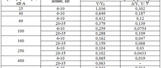
The main parameter is the rated current value. This is the maximum current that this device can withstand over a long service life, remaining in working order and maintaining its protective characteristics. You will find this number on the front panel of the device; it must correspond to one of the readings in the standard series - 6, 10, 16, 25, 32, 40, 63, 80, 100 A. This RCD parameter depends on the load of the protected line and the cross-section of the conductors.
The RCD connection diagram provides for the joint installation of this device with circuit breakers.
This is important to remember, because the RCD only protects against current leaks, and the machine will react to disconnecting the circuit in short circuit and overload mode. The video shows whether it is possible to connect an RCD if there is no grounding in the apartment:
The video shows whether it is possible to connect an RCD if there is no grounding in the apartment:
In terms of rated current, the RCD must be selected an order of magnitude higher than the machine installed in pair with it.
The next important parameter is the rated residual current. This is the required leakage current value to turn off the RCD. There is also a standard series for differential currents, the values in which are normalized in milliamps - 6, 10, 30, 100, 300, 500 mA. But on an RCD this figure is indicated in amperes - respectively, 0.006, 0.01, 0.03, 0.1, 0.3, 0.5 A. You will also find this parameter on the device body.
To protect people at the RCD, it is necessary to set the leakage current setting to 30 mA, because values that are higher will lead to injury, electrical injury and even death. Since the environment in damp rooms is considered the most dangerous, a setting of 10 mA is selected on the RCDs protecting them.
We hope that by understanding the main purpose of the RCD and the principle of its operation, you will not neglect this important element of protection and make your life safe.