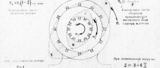
What is an asynchronous motor?
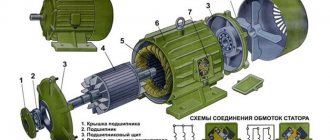
AC electric motors have found quite wide application in various spheres of our life, in hoisting, processing, and measuring equipment. They are used to convert electrical energy that comes from the network into mechanical energy of a rotating shaft. Most often, asynchronous AC converters are used. In them, the rotation speed of the rotor and stator is different. A structural air gap is provided between these active elements.
Both the stator and the rotor have a rigid core made of electrical steel (composited type, made of plates), acting as a magnetic circuit, as well as a winding that fits into the structural grooves of the core. It is the way in which the rotor winding is organized or laid out that is the key criterion for classifying these machines.
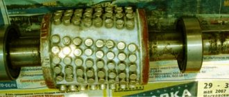
Squirrel-cage motors (SCR)
Here, a winding is used in the form of aluminum, copper or brass rods, which are inserted into the grooves of the core and closed on both sides by disks (rings). The type of connection of these elements depends on the engine power: for small values, the method of joint casting of disks and rods is used, and for large values, separate production is used, followed by welding to each other. The stator winding is connected using delta or star circuits.
Wound rotor motors
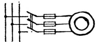
The three-phase rotor winding is connected to the network via slip rings on the main shaft and brushes. The “star” scheme is taken as the basis. The figure below shows a typical design of such an engine.
Lecture on the topic “Losses and efficiency of an asynchronous motor”
Losses and efficiency of an asynchronous motor
The conversion of electrical energy into mechanical energy in an asynchronous motor, as in other electrical machines, is associated with energy losses, therefore the useful power at the output of the motor P2 is always less than the power at the input (power consumption) P1 by the amount of losses ∑P:
Р 2
= Р 1 — ∑
Р (13.1)
Losses ∑Р are converted into heat, which ultimately leads to heating of the machine. Losses in electrical machines are divided into basic and additional. The main losses include magnetic, electrical and mechanical.
Magnetic losses PM in an asynchronous motor are caused by hysteresis losses and eddy current losses that occur in the core when it is remagnetized. The magnitude of magnetic losses is proportional to the magnetization reversal frequency Рм= f
β,
where β = 1.3 ÷ 1.5. The frequency of magnetization reversal of the stator core is equal to the frequency of the current in the network ( f
=
f 1
), and the frequency of magnetization reversal of the rotor core
is f
=
f
2 =
f
1s. At a current frequency in the network
f
1 = 50 Hz with a nominal slip snom = 1 ÷ 8%, the frequency of magnetization reversal of the rotor
is f
=
f
2 = 2 ÷ 4 Hz, Therefore, magnetic losses in the rotor core are so small that they are not taken into account in practical calculations.
Electrical losses in an asynchronous motor are caused by heating of the stator and rotor windings by currents passing through them. The magnitude of these losses is proportional to the square of the current in the winding (W):
electrical losses in the stator winding
R e1
= m 1 I 2 1 r 1
; (13.2)
electrical losses in the rotor winding
R e2
= m 2 I 2 2 r 2 = m 1 I ′ 2 1 r ′ 1
(13.3)
Here r1 and r2 are the active resistances of the stator and rotor phase windings, recalculated to the operating temperature Θwork (see § 8.4):
r 1
= r 1.20 [1 + α (Θ slave - 20)]; r 2 = r 2.20 [1 + α (Θ pa6 - 20)]
, (13.4)
where r1.20 and r2.20 are the active resistance of the windings at a temperature Θ1= 20 °C; α is the temperature coefficient, for copper and aluminum α = 0.004.
Electrical losses in the rotor are directly proportional to slip:
Р e2
= s Р em
(13.5)
where Rem is the electromagnetic power of the asynchronous motor, W:
R em
= R 1 – (R m + R e1 )
(13-6)
From (13.5) it follows that the operation of an asynchronous motor is more economical at low slips, since with increasing slip, electrical losses in the rotor increase.
In asynchronous motors with a wound rotor, in addition to the listed electrical losses, there are also electrical losses in the brush contact Re.sh = 3 I2ΔUsh /2, where Ush = 2.2 V is the transient voltage drop across a pair of brushes.
Mechanical losses Pmech are losses due to friction in bearings and ventilation. The magnitude of these losses is proportional to the square of the rotor speed (Pmekh = n22). In asynchronous motors with a wound rotor, mechanical losses also occur due to friction between the brushes and slip rings of the rotor.
Additional losses include all types of hard-to-account losses caused by the action of higher harmonics of the MMF, pulsation of magnetic induction in the teeth and other reasons. In accordance with GOST, the additional losses of asynchronous motors are taken equal to 0.5% of the power P1 supplied to the motor:
P to6
= 0.005 P 1
. (13.7)
When calculating additional losses for non-nominal mode, one should use the expression
P ′ ext
= P ext β 2
(13-8)
where β = I1/ I1nom—load factor.
Sum of all losses of an asynchronous motor (W)
∑ P = Р em
+ Р e1 + Р e2 + Р fur + Р ext
. (13.9)
In Fig. Figure 13.1 shows the energy diagram of an asynchronous motor, from which it can be seen that part of the power supplied to the motor P1 = m1U1I1cos φ1 is spent in the stator on magnetic P and electrical P1 losses. The remaining electromagnetic power after this is Rem [see. (13.6)] is transmitted to the rotor, where it is partially spent on electrical losses Ре2 and is converted into total mechanical power Р′2. Part of the power goes to cover mechanical Rmechanical additional losses Pdob, and the remaining part of this power P2 constitutes the useful power of the engine.
The efficiency of an asynchronous motor is
η = P 2 / P 1
=1 - ∑P
. (13.10)
Electrical losses in the windings RE1 and RE2 are variable losses, since their value depends on the engine load, i.e., on the current values in the stator and rotor windings [see. (13.2) and (13.3)]. Additional losses (13.8) are also variable. As for the magnetic Rmi of mechanical Rmech, they are practically independent of the load (the exception is motors in which the rotation speed changes over a wide range with changes in load).
The efficiency of an asynchronous motor also changes its value with changes in load: in idle mode the efficiency is zero, and then with increasing load it increases, reaching a maximum at a load of (0.7 ÷ 0.8) Pnom. With a further increase in load, the efficiency decreases slightly, and with overload (P2 Pnom) it decreases sharply, which is explained by the intensive increase in variable losses (Re1+ Re2+ Pdob), the value of which is proportional to the square of the stator current, and a decrease in the power factor. Graph of efficiency versus load η = f
(β) for asynchronous motors has a form similar to that shown in Fig. 1.41 (see Fig. 13.7).
The efficiency of three-phase asynchronous motors for general purpose at rated load is: for motors with power from 1 to 10 kW ηnom= 75 ÷ 88%, for motors with power more than 10 kW ηnom=90 ÷ 94%.
Rice. 13.1. Energy diagram of an asynchronous motor
Example 13.1. A three-phase asynchronous motor operates from a 660 V mains voltage when the stator windings are connected with a star. At rated load, it consumes power P1 = 16.7 kW from the network with a power factor cos c1 = 0.87. Rotation frequency nnom = 1470 rpm. It is required to determine the efficiency of the motor 3 hom if magnetic losses Рм = 265 W, and mechanical losses Рмех = 123 W. The active resistance of the stator winding phase is r1.20 = 0.8 Ohm, and the heat resistance class of the motor insulation is F (operating temperature Ira6 = 115 ° C).
SolutionCurrent in stator winding phase
I1nom ===16.8 A
where U1 = 380 V.
Stator winding phase resistance, recalculated to operating temperature
θwork = 115 °С, according to (13.4)
r1 = r1.20 [1 + b (Irab - 20)] = 0.8[1 + 0.004(115 - 20)] = 1.1 Ohm.
Electrical losses in the stator winding according to (13.2)
Re1 = m1 I21nom r1 = 3 * 16.82 * 1.1 = 93 1 W.
Electromagnetic power of the motor according to (13.6)
REM = P1 - (Pm + Re1) = 16.7 * 103 - (265 + 931) = 15504 W.
Nominal slip snom = (n1 - nnom)/ n1 = (1500 - 1470)/1500 = 0.020. Electrical losses in the rotor winding according to (13.5)
Re2 =snom Rem = 0.020 * 15504 = 310 W.
Additional losses according to (13.7)
Рdo6 = 0.005 Р1 =0.005 * 16.7 * 103 =83 W.
Total losses according to (13.9)
P = Pm + Re1 + Re2 + Pmech + Pmex = 265 + 931 + 310 + 123 + 83 = 1712 W.
Engine efficiency in nominal mode according to (13.10)
ηnom = 1 - P/ P1 = 1 - 1712/ (16.7 * 103) = 0.898, or 89.8%.
Efficiency is one of the main parameters of an asynchronous motor, which determines its energy properties - efficiency during operation. In addition, the efficiency of the engine, or rather the amount of losses in it, regulates the heating temperature of its main parts and, first of all, its stator winding. For this reason, motors with low efficiency (under the same cooling conditions) operate at a higher heating temperature of the stator winding, which leads to a decrease in their reliability and durability (see § 8.4).
To do your homework, you need to know the structure and principle of operation of an asynchronous motor and the relationships between the electrical quantities that characterize its operation.
Three-phase asynchronous motor with squirrel-cage rotor at rated power P 2
, voltage
U nom
, and current
I nom
P 1
from the network .
The engine efficiency is η nom
, and the power factor
cos φ nom
.
Losses in stator windings R o1
, in stator steel
R st1
, in rotor windings
R o2
, mechanical
losses
R m.p. Total losses in the engine ∑р
.
Electromagnetic power transmitted by the magnetic flux to the rotor, R em
.
The engine develops rated torque M nom
and electromagnetic torque
M em
at rotational speed
n 2
. Determine the values marked with dashes in table1.
Draw an energy diagram of the engine to scale.
Table 1
| Var. no. | R2 | U nom | I nom | R1 | η nom | cosφ | R o1 | R st1 | P o2 | R m.p | ∑R | R em | M nom | M um | n2 |
| kW | IN | A | kW | kW | kW | kW | kW | kW | kW | Nm | Nm | rpm | |||
| — | 15,8 | — | 0,88 | — | 0,25 | — | 0,15 | — | — | 4.73 | 29,8 | — | |||
| — | — | 2,91 | 0,86 | 0,82 | — | 0,1 | 0,08 | 0,05 | — | — | 8,22 | — | — | ||
| 4,5 | — | — | — | 0,85 | 0,25 | — | 0,15 | 0,08 | 0,62 | — | 29,8 | — | — | ||
| — | 5,38 | — | 0,86 | 0,82 | 0,18 | 0,1 | 0,08 | — | — | — | — | — | |||
| — | 22,4 | — | — | — | — | 0,4 | — | 0,2 | 2,2 | 20,8 | — | ||||
| — | 14,2 | — | — | 0,85 | — | 0,2 | — | 0,11 | 0,96 | 7,36 | — | — | |||
| — | — | 22,4 | 22,2 | — | 0,87 | — | 0,6 | — | 2,2 | 20,8 | — | — | |||
| 2,5 | — | 5,38 | — | 0,86 | 0,82 | 0,18 | — | — | 0,05 | — | 2,53 | — | 8,33 | — | |
| — | 22,2 | — | 0,87 | 0,4 | — | 0,2 | — | — | — | 20,8 | — | ||||
| — | 14,2 | 7,96 | — | — | 0,4 | — | 0,25 | — | 0,96 | — | — | 7,36 |
Control questions:
1. What is the essence of active and reactive power of an asynchronous motor?
2. What types of losses occur in an asynchronous motor and what is their nature?
3. Define the efficiency of an asynchronous motor.
After analyzing the problem of energy saving, it turned out that more than half of the electricity generated in the world is consumed by electric motors. That’s why all the leading electrical companies in the world are working to improve them.
What are energy-saving motors?
These are electric motors that are 1–10% more efficient than standard motors. In large energy-saving engines, the difference in efficiency values is 1–2%, and in low- and medium-power engines this difference is already 7–10%.
Efficiency of Siemens electric motors
An increase in efficiency in energy-saving engines is achieved through:
- increasing the share of active materials – copper and steel;
- use of thinner and higher quality electrical steel;
- use of copper instead of aluminum in rotor windings;
- reducing the air gap in the stator using precision technological equipment;
- optimization of the shape of the toothed zone of the magnetic core and the design of the windings;
- use of higher class bearings;
- special fan design;
According to statistics, the price of the entire engine is less than 2% of the total life cycle costs. So, if the engine runs 4,000 hours annually for 10 years, then electricity accounts for approximately 97% of the total life cycle costs. Another about one percent is for installation and maintenance. Therefore, an increase in the efficiency of an average power engine by 2% will make it possible to recoup the increase in the cost of an energy-saving engine within 3 years, depending on the operating mode. Practical experience and calculations show that the increase in the cost of an energy-saving engine pays off due to the saved electricity when operating in S1 mode in a year and a half (with an annual operating time of 7000 hours).
In general, the transition to the use of an energy-saving engine allows:
- increase engine efficiency by 1–10%;
- increase the reliability of its operation;
- reduce downtime;
- reduce maintenance costs;
- increase engine resistance to thermal overloads;
- increase overload capacity;
- increase engine stability to deteriorating operating conditions;
- under and overvoltage, distortion of the voltage waveform, phase imbalance, etc.;
- improve power factor;
- reduce noise levels;
- increase engine speed by reducing slip;
The negative properties of electric motors with increased efficiency compared to conventional ones are:
- 10 – 30% higher cost;
- slightly larger mass;
- higher starting current.
In some cases, using an energy-efficient motor is not practical:
- when the engine is in operation for a short time (less than 1–2 thousand hours/year), the introduction of an energy-efficient engine may not make a significant contribution to energy saving;
- when the engine operates in modes with frequent starting, since the saved electricity will be spent on a higher starting current;
- when the engine is running, it operates underload, due to a decrease in efficiency when operating at a load below the rated load.
The amount of energy savings resulting from the implementation of an energy efficient motor may be insignificant compared to the potential of a variable speed drive. Each additional percentage of efficiency requires an increase in the mass of active materials by 3-6%. In this case, the moment of inertia of the rotor increases by 20–50%. Therefore, highly efficient engines are inferior to conventional engines in terms of dynamic performance, unless this requirement is specifically taken into account during their development.
When choosing an energy-efficient engine, you need to carefully consider the issue of price. According to analysts, copper will rise in price much faster than steel. Therefore, where it is possible to use so-called steel motors (with a smaller groove area), it is better to use them. Such motors have a lower cost due to copper savings. For the same reasons, it is necessary to treat energy-saving permanent magnet motors. If you have to look for a replacement for such an engine in the future. It may turn out that its price will be too high, and replacing it with an energy-saving motor of general industrial design will be difficult due to the discrepancy in dimensions. According to experts, permanent magnets made of rare earth materials will become more expensive and faster than copper, which will lead to a significant increase in the price of such motors. Although such motors, with the highest class of energy efficiency, are quite compact, their introduction into industry is limited by the fact that permanent magnets are now in demand in other industries than the general industry, and, according to experts, they will be used in the production of special equipment, on which no expense is spared.
“Energy efficient electric motors
Energy efficiency concept
Energy efficiency refers to the rational use of energy resources, through which a reduction in energy consumption is achieved at the same level of load power.
In Fig. 1a, b show examples of irrational and rational use of energy. The powers Рн of receivers 1 and 2 are the same, while the losses ΔР1, released in receiver 1, significantly exceed the losses ΔР2, which are released in receiver 2. As a consequence, the power consumed ΔРп1 by receiver 1 is greater than the power ΔРп2 consumed by receiver 2. Thus, receiver 2 is energy efficient compared to receiver 1.
Receiver 1
Rice. 1a. Waste of energy
Receiver 2
Rice. 1b. Efficient use of energy
In the modern world, special attention is paid to energy efficiency issues. This is partly explained by the fact that solving this problem can lead to the achievement of the main goals of international energy policy:
- improving energy security;
- reducing harmful environmental impacts due to the use of energy resources;
- increasing the competitiveness of industry as a whole.
Recently, a number of energy efficiency initiatives and measures have been adopted at regional, national and international levels.
Energy strategy of Russia
Russia has developed an Energy Strategy, which involves the deployment of an energy efficiency program as part of a comprehensive energy saving policy. This program is aimed at creating basic conditions for accelerated technological renewal of the energy industry, the development of modern processing plants and transport capacities, as well as the development of new, promising markets.
On November 23, 2009, the President of the Russian Federation D.A. Medvedev signed Federal Law No. 261-FZ “On energy saving and increasing energy efficiency and on introducing amendments to certain legislative acts of the Russian Federation.” This law creates a fundamentally new attitude to the process of energy saving. It clearly outlines the powers and requirements in this area for all levels of government, and also lays the foundation for achieving real results. The law introduces an obligation to account for energy resources for all enterprises. Organizations whose total annual costs for energy consumption exceed 10 million rubles are proposed to be required to undergo energy inspections until December 31, 2012 and then at least once every 5 years, based on the results of which an energy passport of the enterprise is drawn up, recording progress on the energy efficiency scale.
With the adoption of the law 'On Energy Efficiency', one of the key articles of the document were amendments to the Tax Code (Article 67 part 1), which exempt from income tax enterprises using facilities with the highest energy efficiency class. The Russian government is ready to provide subsidies and reduce the tax burden to those enterprises that are ready to raise their equipment to the level of energy-saving equipment.
Energy efficiency of electric motors
According to RAO UES of Russia data for 2006, about 46% of the electricity generated in Russia is consumed by industrial enterprises (Fig. 1), half of this energy is converted into mechanical energy through electric motors.
Rice. 2. Structure of electricity consumption in Russia
During the process of energy conversion, part of it is lost in the form of heat. The amount of lost energy is determined by the energy performance of the engine. The use of energy-efficient electric motors can significantly reduce energy consumption and reduce the carbon dioxide content in the environment.
The main indicator of the energy efficiency of an electric motor is its efficiency factor (hereinafter referred to as efficiency)
:
η=P2/P1=1 – ΔP/P1,
where P2 is the useful power on the electric motor shaft, P1 is the active power consumed by the electric motor from the network, ΔP is the total losses occurring in the electric motor.
Obviously, the higher the efficiency (and, accordingly, the lower the losses), the less energy the electric motor consumes from the network to create the same power P2. To demonstrate energy savings when using energy-efficient motors, let’s compare the amount of power consumed using the example of ABB electric motors of the conventional (M2AA) and energy-efficient (M3AA) series (Fig. 3).
1. M2AA series
(energy efficiency class IE1): power Р2=55 kW, rotation speed n=3000 rpm, η=92.4%, cosφ=0.91
Active power consumed from the network:
Р1=Р2/η=55/0.924=59.5 kW.
Total losses:
ΔP=P1–P2=59.5-55=4.5 kW.
Assuming that a given engine runs 24 hours a day, 365 days a year, the amount of energy lost and released as heat
Q=4.5·24·365=39420 kW.
With an average cost of electricity of 2 rubles. per kW/h the amount of lost electricity for 1 year in monetary terms
C=2·39420=78840 rub.
2. M3AA series
(energy efficiency class IE2): power Р2=55 kW, rotation speed n=3000 rpm, η=93.9%, cosφ=0.88
Active power consumed from the network:
Р1=Р2/η=55/0.939=58.6 kW.
Total losses:
ΔP=P1–P2=58.6-55=3.6 kW.
Assuming that a given engine runs 24 hours a day, 365 days a year, the amount of energy lost and released as heat
Q=3.6·24·365=31536 kW.
With an average cost of electricity of 2 rubles. per kW/h the amount of lost electricity for 1 year in monetary terms
C=2·31536=63072 rub.
Thus, if a conventional electric motor (IE1 class) is replaced by an energy efficient one (IE2 class), the energy savings amount to 7884 kW per year per motor. When using 10 such electric motors, the savings will be 78,840 kW per year or in monetary terms 157,680 rubles/year. Thus, the efficient use of electricity allows the enterprise to reduce the cost of its products, thereby increasing its competitiveness.
The cost difference of electric motors with energy efficiency classes IE1 and IE2, amounting to 15,621 rubles, pays off in approximately 1 year.
Rice. 3. Comparison of a conventional electric motor with an energy efficient one
It should be noted that with increasing energy efficiency, the service life of the engine also increases.
. This is explained as follows. The source of engine heating is the losses generated in it. Losses in electrical machines (EM) are divided into basic, caused by electromagnetic and mechanical processes occurring in the EM, and additional, caused by various secondary phenomena. The main losses are divided into the following classes:
- 1. mechanical losses (including ventilation losses, losses in bearings, losses due to friction of brushes on the commutator or slip rings);
- 2. magnetic losses (losses due to hysteresis and eddy currents);
- 3. electrical losses (losses in windings when current flows).
According to the empirical law, the service life of insulation decreases by half with an increase in temperature by 100C. Thus, the service life of a motor with increased energy efficiency is somewhat longer, since losses and therefore heating of an energy-efficient motor are less.
Ways to improve engine energy efficiency:
- 1. The use of electrical steels with improved magnetic properties and reduced magnetic losses;
- 2. The use of additional technological operations (for example, annealing to restore the magnetic properties of steels, which, as a rule, deteriorate after machining);
- 3. Use of insulation with increased thermal conductivity and electrical strength;
- 4. Improving aerodynamic properties to reduce ventilation losses;
- 5. Use of high quality bearings (NSK, SKF);
- 6. Increasing the accuracy of processing and manufacturing of engine components and parts;
- 7. Using the motor in conjunction with a frequency converter.
Another important parameter characterizing the energy efficiency of an electric motor is the load factor cosφ. The load factor determines the share of active power in the total power supplied to the electric motor from the network.
cosφ=Р1/S,
where S is the total power.
In this case, only active power is converted into useful power on the shaft, reactive power is needed only to create an electromagnetic field. Reactive power enters the motor and returns back to the network at twice the 2f network frequency, thereby creating additional losses in the supply lines. Thus, a system consisting of motors with high efficiency values but low cosφ values cannot be considered energy efficient.
Barriers to the implementation of energy efficient electric drive systems
Despite the high effectiveness of energy-efficient solutions, today there are a number of obstacles to the spread of energy-efficient electric drive systems:
- 1. Replacing only one or two electric motors in an entire enterprise is an insignificant measure;
- 2. Low level of consumer awareness in the field of energy efficiency classes of engines, their differences and existing standards;
- 3. Separate financing in many enterprises: the budget manager for the purchase of electric motors is often not the person who deals with issues of reducing the cost of production or incurs annual maintenance costs;
- 4. Purchase of electric motors as part of complex equipment, the manufacturers of which often install low-quality electric motors in order to reduce the cost of products;
- 5. Within the same company, the costs of purchasing equipment and energy consumption over the service life are often paid under different headings;
- 6. Many enterprises have stocks of electric motors, usually of the same type and the same efficiency class.
An important aspect in matters related to the energy efficiency of electrical machines
, is to popularize the decision to purchase equipment based on an assessment of the total operating costs over its service life.
New international standards regulating the energy efficiency of electric motors.
In 2007, 2008 IEC has introduced two new standards regarding the energy efficiency of electric motors
: standard IEC/EN 60034-2-1 sets new rules for determining efficiency, standard IEC 60034-30 sets new energy efficiency classes for electric motors.
The IEC 60034-30 standard establishes three energy efficiency classes for three-phase squirrel-cage induction motors (Fig. 1).
Rice. 4. Energy efficiency classes according to the new IEC 60034-30 standard
Currently, the designation of energy efficiency classes can often be seen in the form of the following combinations: EFF3, EFF2, EFF1. However, the class boundaries (Fig. 2) were established by the old IEC 60034-2 standard, which was replaced by the new IEC 60034-30 (Fig. 1).
Rice. 5. Energy efficiency classes according to the old IEC 60034-2 standard
Operating principle and speed of asynchronous motors
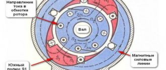
Let's consider this issue using the example of ADKR, as the most common type of electric motors in lifting, transport and processing equipment. The mains voltage is supplied to the stator winding, each of the three phases of which is geometrically displaced by 120°. After applying voltage, a magnetic field arises, which creates, by induction, an emf and a current in the rotor windings. The latter causes electromagnetic forces that cause the rotor to rotate. Another reason why all this happens, namely, EMF occurs, is the difference in the speed of the stator and rotor.
One of the key characteristics of any ADCR is the rotation speed, which can be calculated using the following relationship:
n=60f/p, rpm
where f is the frequency of the mains voltage, Hz; p – number of stator pole pairs.
All technical characteristics are indicated on a metal plate attached to the body. But if it is missing for some reason, then the number of revolutions must be determined manually using indirect indicators. Typically, three main methods are used:
- Calculation of revolutions taking into account the diametric pitch of the winding. To determine, a formula of the form is used:
where 2p – number of poles; Z1 – number of slots in the stator core; y – actually, the step of laying the winding.
Standard speed values:
- Calculation of the number of poles along the stator core. Mathematical formulas are used, which take into account the geometric parameters of the product:
2p = 0.35Z1b/h or 2p = 0.5Di/h,
where 2p – number of poles; Z1 – number of slots in the stator; b – tooth width, cm; h – backrest height, cm; Di is the internal diameter formed by the teeth of the core, cm.
After this, based on the data obtained and magnetic induction, it is necessary to determine the number of turns, which is checked against the motors’ passport data.
Ways to change engine speed
Adjusting the speed of any three-phase electric motor used in lifting and transport machinery and equipment allows you to achieve the required operating modes accurately and smoothly, which is not always possible, for example, due to mechanical gearboxes. In practice, seven main methods of rotation speed correction are used, which are divided into two key areas:
- Change in the speed of the magnetic field in the stator. Achieved by frequency regulation, switching the number of pole pairs or voltage correction. It should be added that these methods are applicable to electric motors with squirrel-cage rotor;
- Changing the amount of slip. This parameter can be adjusted by using the supply voltage, connecting additional resistance to the electrical circuit of the rotor, using a valve cascade or dual power supply. Used for models with wound rotor.
The most popular methods are voltage and frequency regulation (through the use of converters), as well as changing the number of pole pairs (implemented by organizing an additional winding with switching capability).
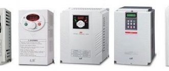
Typical speed controller circuits
There is a wide selection of regulators and frequency converters for asynchronous motors on the market today. However, for the domestic needs of lifting or processing equipment, it is quite possible to calculate and assemble a homemade device on a microcircuit based on thyristors or powerful transistors.
Below is an example of a circuit of a fairly powerful regulator for an asynchronous motor. Due to this, you can achieve smooth control of its operating parameters, reduce energy consumption by up to 50%, and reduce maintenance costs.
This scheme is complex. For domestic needs, it can be significantly simplified by using a triac, for example, VT138-600, as a working element. In this case, the diagram will look like this:
The motor speed will be regulated by a potentiometer, which determines the phase of the input pulse that opens the triac.
As can be judged from the information presented above, not only its operating parameters, but also the efficiency of the powered lifting or processing equipment depend on the speed of an asynchronous motor. Today you can purchase a wide variety of regulators in the retail chain, but you can also make calculations and assemble an effective device with your own hands.
Single-phase asynchronous motors are powered from a conventional 220 V alternating voltage network.
The most common design of such motors contains two (or more) windings - working and phase-shifting. The working one is fed directly, and the additional one is fed through a capacitor, which shifts the phase by 90 degrees, which creates a rotating magnetic field. Therefore, such motors are also called two-phase or capacitor motors.
It is necessary to regulate the rotation speed of such motors, for example, for:
- changes in air flow in the ventilation system
- pump performance control
- changes in the speed of moving parts, for example in machine tools, conveyors
In ventilation systems, this allows you to save energy, reduce the level of acoustic noise of the installation, and set the required performance.
Methods of regulation
We will not consider mechanical methods of changing the rotation speed, for example gearboxes, couplings, gear transmissions. We will also not touch upon the method of changing the number of poles of the windings.
Let's consider methods with changing electrical parameters:
- change in motor supply voltage
- change in supply voltage frequency
What does the converter provide?
The need to use an electric motor speed controller in the case of asynchronous models is as follows:
Significant savings in electrical energy are achieved. Since not all equipment requires high rotation speeds of the motor shaft, it makes sense to reduce it by a quarter.
Reliable protection of all mechanisms is provided. The frequency converter allows you to control not only temperature, but also pressure and other system parameters. This fact is especially important if a pump is driven by a motor.
A pressure sensor is installed in the container and sends a signal when the required level is reached, causing the motor to stop.
A soft start is performed. Thanks to the regulator, the need to use additional electronic devices is eliminated. The frequency converter is easy to set up and get the desired effect.
Maintenance costs are reduced because the regulator minimizes the risk of damage to the drive and other mechanisms.
Thus, electric motors with speed control turn out to be reliable devices with a wide range of applications.
It is important to remember that the operation of any equipment based on an electric motor will only be correct and safe when the rotation speed parameter is adequate to the conditions of use.
Voltage regulation
Speed control in this way is associated with a change in the so-called engine slip - the difference between the rotation speed of the magnetic field created by the stationary engine stator and its moving rotor:
n1— magnetic field rotation speed
n2 — rotor rotation speed
In this case, sliding energy is necessarily released - which causes the motor windings to heat up more.
This method has a small control range, approximately 2:1, and can also only be carried out downwards - that is, by reducing the supply voltage.
When regulating speed in this way, it is necessary to install oversized motors.
But despite this, this method is used quite often for low-power motors with a fan load.
In practice, various regulator circuits are used for this.
Autotransformer voltage regulation
An autotransformer is an ordinary transformer, but with one winding and taps from some of the turns. In this case, there is no galvanic isolation from the network, but in this case it is not needed, so savings are achieved due to the absence of a secondary winding.
The diagram shows autotransformer T1 , switch SW1 , which receives taps with different voltages, and motor M1.
The adjustment is done in steps; usually no more than 5 steps of regulation are used.
Advantages of this scheme:
- undistorted output voltage waveform (pure sine wave)
- good overload capacity of the transformer
Flaws:
- large mass and dimensions of the transformer (depending on the power of the load motor)
- all the disadvantages inherent in voltage regulation
Thyristor engine speed controller
This circuit uses keys - two thyristors connected back-to-back (the voltage is alternating, so each thyristor passes its own half-wave of voltage) or a triac.
The control circuit regulates the moment of opening and closing of the thyristors relative to the phase transition through zero; accordingly, a piece is “cut off” at the beginning or, less often, at the end of the voltage wave.
This changes the rms voltage value.
This circuit is quite widely used to regulate active loads - incandescent lamps and all kinds of heating devices (so-called dimmers).
Another method of regulation is to skip half-cycles of the voltage wave, but at a network frequency of 50 Hz this will be noticeable for the motor - noise and jerking during operation.
To control motors, regulators are modified due to the characteristics of the inductive load:
- install protective LRC circuits to protect the power switch (capacitors, resistors, chokes)
- add a capacitor at the output to adjust the voltage waveform
- limit the minimum voltage regulation power - for guaranteed engine start
- use thyristors with a current several times higher than the electric motor current
Advantages of thyristor regulators:
Flaws:
- can be used for low power engines
- During operation, noise, crackling, and jerking of the engine may occur.
- when using triacs, a constant voltage is applied to the motor
- all the disadvantages of voltage regulation
It is worth noting that in most modern mid- and high-level air conditioners, the fan speed is adjusted in this way.
Transistor voltage regulator
As the manufacturer himself calls it, an electronic autotransformer or PWM regulator.
The voltage is changed using the PWM (pulse width modulation) principle, and transistors are used in the output stage - field-effect or bipolar with insulated gate (IGBT).
The output transistors are switched at a high frequency (about 50 kHz); if you change the width of the pulses and pauses between them, the resulting voltage at the load will also change. The shorter the pulse and the longer the pause between them, the lower the resulting voltage and power input.
Frequency regulation
Just recently (10 years ago), there were a limited number of frequency controllers for motor speeds on the market, and they were quite expensive. The reason was that there were no cheap high-voltage power transistors and modules.
But developments in the field of solid-state electronics have made it possible to bring power IGBT modules to the market. As a consequence, there is a massive appearance on the market of inverter air conditioners, welding inverters, and frequency converters.
At the moment, frequency conversion is the main way to regulate the power, performance, speed of all devices and mechanisms driven by an electric motor.
However, frequency converters are designed to control three-phase electric motors.
Single-phase motors can be controlled by:
- specialized single-phase inverters
- three-phase inverters with the exception of the capacitor
Converters for single-phase motors
Currently, only one manufacturer announces serial production of a specialized inverter for capacitor motors - INVERTEK DRIVES.
Optidrive E2 model
For stable engine starting and operation, special algorithms are used.
In this case, frequency adjustment is possible upward, but in a limited frequency range, this is prevented by a capacitor installed in the phase-shifting winding circuit, since its resistance directly depends on the frequency of the current:
f - current frequency
C - capacitance of the capacitor
The output stage uses a bridge circuit with four output IGBT transistors:
Optidrive E2 allows you to control the motor without removing the capacitor from the circuit, that is, without changing the motor design - in some models this is quite difficult to do.
Advantages of a specialized frequency converter:
- intelligent motor control
- Stably stable engine operation
- Huge capabilities of modern inverters:
- the ability to control the operation of the engine to maintain certain characteristics (water pressure, air flow, speed under changing load)
- numerous protections (motor and device itself)
- sensor inputs (digital and analogue)
- various outputs
- communication interface (for control, monitoring)
- preset speeds
- PID controller
Disadvantages of using a single-phase inverter:
Using a state of emergency for three-phase motors
A standard frequency converter has a three-phase voltage at its output. When connecting a single-phase motor to it, remove the capacitor from it and connect it according to the diagram below:
The geometric arrangement of the windings relative to each other in the stator of an asynchronous motor is 90°:
The phase shift of the three-phase voltage is -120°, as a consequence of this - the magnetic field will not be circular, but pulsating and its level will be less than with a power supply with a shift of 90°.
In some capacitor motors, the additional winding is made of thinner wire and therefore has a higher resistance.
When operating without a capacitor, this will lead to:
- stronger heating of the winding (service life is reduced, short circuits and interturn short circuits are possible)
- different current in the windings
Many inverters have protection against current asymmetry in the windings; if it is impossible to disable this function in the device, operation using this circuit will be impossible
Advantages:
- lower cost compared to specialized inverters
- Huge selection of power and manufacturers
- wider frequency control range
- all the advantages of the inverter (inputs/outputs, intelligent operating algorithms, communication interfaces)
Disadvantages of the method:
- the need for preliminary selection of the inverter and motor for joint operation
- pulsating and reduced torque
- increased heating
- no warranty in case of failure, because Three-phase inverters are not designed to work with single-phase motors
Due to their reliability and simplicity of design, asynchronous motors (IM) have become widespread. Most machine tools, industrial and household equipment use electric motors of this type. The rotation speed of the motor is changed mechanically (by additional load on the shaft, ballast, transmission mechanisms, gearboxes, etc.) or electrically. Electrical regulation is more complex, but also much more convenient and versatile.
For many units, electrical control is used. It provides precise and smooth control of engine starting and operation. Electrical control is achieved through:
- changes in current frequency;
- current strength;
- voltage level.
In this article we will look at popular methods of how the speed of an asynchronous motor can be adjusted at 220 and 380V.
What are core and iron losses?
In some ways, these costs are divided into eddy current loss and hysteresis. The former can be minimized by using the layers present on the core. Once they are used, the area will be smaller, and the resistance, accordingly, will be higher, thereby reducing the eddy currents.
For example, hysteresis losses can be minimized by using high quality silicon steel. This affects the construction.
The loss of the core depends on what the voltage frequency is. The stator has a frequency of only 50 Hz, and the rotor has an even lower frequency - 1.5 Hz, and all this is due to the fact that under normal operating conditions the slip is no more than 3%. As a result, the losses of the rotor cores are small when compared with the costs of the stator cores. It is precisely by mistake that some people prefer to neglect them in working condition.
Regarding brush friction losses and mechanical
Induction motors with a wound rotor may experience loss of brush friction. Mechanical loss can be encountered in bearings. At the start, they are all at zero, but as the speed increases, spending will only increase. In three-phase motors, the speed is always constant. We can conclude that this loss will be permanent, and the construction depends on it.
Features of variable losses
This type of loss is also called copper reduction. They can occur due to electric currents passing through the rotor and stator windings. As the load changes, this current will also change along with these reductions. This gave rise to the name variable losses. They are obtained by conducting tests with locked rotors of 3-phase motors.
Important!
The main function of these drives is to convert electrical energy into mechanical energy. During it, the energy will go through several different stages. As it passes through different stages, it will be displayed on a diagram indicating the flow of energy. Everyone knows that at the input of three-phase asynchronous motors the supply is also three-phase. Therefore, it will go to the side of the 3-phase electric motor.
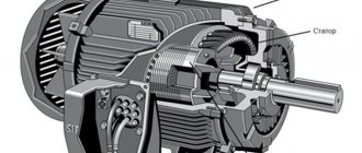
Rotor and Stator
Part of this input energy is used to support the stator deficiencies. And their role is played by the deficiency of stator copper and iron. The energy that is saved will go to the rotor at the input. It already converts these inputs to the rotor into mechanical energy. But this input cannot be converted into the same output, since it maintains a lack of energy on the rotor. When the rotor rotates, the iron consumption will depend on the frequency of the rotor, and it is extremely small. But they prefer to ignore this. So it would be better if the input to the rotor was supported by copper losses.
After energy is created, it will go to the load through the shafts. The appearance of small mechanical costs (air resistance and friction) cannot be avoided. Therefore, the total reproducible energy of a mechanical nature must be supplied to maintain those same losses.
Calculation of mechanical characteristics of asynchronous motors
The natural characteristics of the mechanical design of such motors correspond to the basic (passport) circuits for its connection and the nominal parameters of the supply voltage. But their artificial analogue will be obtained when some of the additional elements are included:
- capacitors;
- reactors;
- resistors.
When the engine is powered by a non-rated voltage, the characteristics will differ from the natural characteristics - they are extremely convenient and useful as a tool when analyzing the static and dynamic modes of electric drives. There are both artificial characteristics of electric motors and natural ones.
Changing the speed of an IM with a squirrel-cage rotor
There are several ways:
- Rotation control by changing the electromagnetic field of the stator: frequency regulation and changing the number of pole pairs.
- Changing the slip of the electric motor by decreasing or increasing the voltage (can be used for IMs with a wound rotor).
Frequency regulation
In this case, the adjustment is made using a frequency conversion device connected to the engine. For this purpose, powerful thyristor converters are used. The process of frequency regulation can be considered using the example of the EMF formula of a transformer:
This expression means that in order to maintain a constant magnetic flux, which means maintaining the overload capacity of the electric motor, the supply voltage level should be adjusted simultaneously with frequency conversion. If the expression calculated by the formula is saved:
then this means that the critical moment has not been changed. And the mechanical characteristics correspond to the figure below; if you do not understand what these characteristics mean, then in this case the adjustment occurs without loss of power and torque.
Mechanical characteristics
As the main one, it helps to conduct a detailed analysis of the operation of the electric motor. It expresses the direct dependence of the rotor speed on the electromagnetic torque n=f (M).
The graph shows that in sections 1-3 the machine operates stably. 3-4 - immediate segment of unstable work. Ideal idle speed corresponds to point 1.
Point 2 - nominal operating mode. Point 3 - the rotation speed has reached a critical value. Starting torque Mstart - point 4.
Our readers recommend! To save on electricity bills, our readers recommend the 'Electricity Saving Box'. Monthly payments will be 30-50% less than they were before using the saver. It removes the reactive component from the network, resulting in a reduction in load and, as a consequence, current consumption. Electrical appliances consume less electricity and costs are reduced.
There are technical methods for calculating and constructing mechanical characteristics taking into account data from the passport.
At the initial point 1 n0=60f/p (p is the number of pole pairs). Since nn and Mn are directly the coordinates of point 2, the rated torque is calculated using the formula Mn = 9.55*Рн/ nn, where Рн is the rated power. The value of nn is indicated in the engine passport. At point 3 Mkr=Mnλ. Starting torque at point 4 Mstart=Mn*λstart (values of λ, λstart - from the passport).
A mechanical characteristic constructed in this way is called natural. By changing other parameters you can obtain an artificial mechanical characteristic.
The results obtained make it possible to analyze and harmonize the mechanical properties of the engine itself and the working mechanism.
Methods for controlling the speed of an IM with a wound rotor
The rotation speed of an IM with a wound rotor is changed by changing the slip. Let's look at the main options and methods.
Changing the supply voltage
This method is also used for IMs with a short-circuit rotor. The asynchronous motor is connected through an autotransformer or LATR. If you reduce the supply voltage, the engine speed will decrease.
But this mode reduces the overload capacity of the engine. This method is used for regulation within a voltage range not higher than the rated voltage, since an increase in the rated voltage will lead to failure of the electric motor.
Active resistance in the rotor circuit
When using this method, a rheostat or a set of high-power constant resistors is connected to the rotor circuit. This device is designed to smoothly increase resistance.
Slip increases in proportion to the increase in resistance, and the rotation speed of the electric motor shaft decreases.
- large range of regulation towards lower rotation speed.
- decrease in efficiency;
- increase in losses;
- deterioration of mechanical characteristics.
Asynchronous valve cascade and dual-fed machines
Changing the operating speed of asynchronous electric motors in these cases is done by changing the slip. In this case, the rotation speed of the electromagnetic field remains unchanged. Voltage is supplied directly to the stator windings. The adjustment occurs through the use of sliding power, which is transformed into the rotor circuit and forms an additional EMF. Such methods are used only in special machines and large industrial devices.
Regulating the rotation speed of an asynchronous electric motor
An induction motor (Figure 1) has a stationary part called the stator and a rotating part called the rotor. The magnetic field is created in a winding located in the stator. This design of the electric motor allows you to regulate its rotation frequency in various ways.
Main technical characteristics taken into account when changing the rotation speed
When regulating the rotation speed of asynchronous electric motors, several basic technical indicators should be taken into account, which significantly affect the operation of the motors.
- The control range D, that is, the limit to which it is possible to change the rotation speed. This characteristic is calculated by the ratio of the minimum and maximum rotation speed.
- Smoothness of regulation is determined by the minimum jump in the rotation speed of the electric motor when a transition from one mechanical characteristic to another takes place.
- The direction of change in engine speed (the so-called control zone). Rated operating conditions determine the natural mechanical characteristics of the engine. When the speed control process is carried out, these characteristics (voltage and frequency of the supply network) will begin to change. The result is artificial characteristics that are usually lower than natural ones.
There are several ways to regulate the speed of an electric motor:
Regulating the rotation speed by changing the frequency of the supply network
Regulating the rotation speed by changing the frequency in the supply network is considered one of the most economical control methods, which allows you to achieve excellent mechanical characteristics of the electric drive. When the frequency of the supply network changes, the frequency of rotation of the magnetic field also changes.
The conversion of the standard network frequency, which is 50 Hz, occurs due to the power supply. Simultaneously with the change in frequency, there is also a change in voltage, which is necessary to ensure high rigidity of mechanical characteristics.
Regulating the rotation speed allows you to achieve different operating modes of the electric motor:
- with constant torque;
- with a torque that is proportional to the square of the frequency;
- with constant shaft power.
Electrical machine rotary converters, as well as static frequency converters that operate on semiconductor devices commercially produced by industry, can be used as a power source for regulation.
An undoubted advantage of frequency regulation is the ability to smoothly adjust the rotation speed in both directions from the natural characteristic. When regulated, high rigidity characteristics and excellent overload capacity are achieved.
Speed control by changing the number of poles
Regulating the rotation speed by changing the number of poles occurs by changing the rotation speed of the stator magnetic field. The frequency of the supply network remains unchanged, while the frequency of rotation of the magnetic field and the rotor speed change. They vary inversely with the number of poles. For example, the number of poles is 2, 4, 6, 8, then the engine speed when changing their number will be 3000, 1500, 1000, 750 rpm.
Motors that provide switching of a number of pole pairs usually have a squirrel-cage rotor with a winding. Thanks to this rotor, the engine can operate without additional reconnections in the circuit.
Changing the rotation speed by connecting a rotor with a rheostat to the circuit
Another way to change the engine speed is to include a rotor with a rheostat in the circuit. This method has a significant limitation, since it can only be applied to motors with a wound rotor. It provides a smooth change in rotation speed over a very wide range. The downside is the large energy losses in the control rheostat.
Changing the direction of rotation
Changing the direction of rotation of the motor can be accomplished by changing the direction of rotation of the magnetic field, which is created by the stator windings. Changing the direction of rotation can be achieved by changing the order of current alternation in the phases of the stator winding. To place an order, call the managers of the Kabel.RF® company by phone or send a request by email indicating the required electric motor model, purposes and operating conditions. The manager will help you choose the right brand, taking into account your wishes and needs.
Smooth start of asynchronous electric motors
In addition to unconditional advantages, ADs have significant disadvantages. This is a jerk at the start and high starting currents, 7 times higher than the rated ones. To soft start the electric motor, the following methods are used:
- switching of windings according to the star-delta circuit;
- turning on the electric motor through an autotransformer;
- use of specialized devices for soft starting.
Most frequency controllers have a soft motor start function. This not only reduces inrush currents, but also reduces the load on the actuators. Therefore, frequency regulation and soft starting are quite closely related.
How to make a device for changing the rotation speed of an electric motor with your own hands
Dimmers can be used to regulate low-power single-phase IM. However, this method is unreliable and has serious disadvantages: reduced efficiency, serious overheating of the device and the risk of engine damage.
For reliable and high-quality regulation of the speed of 220V electric motors, frequency regulation is best suited.
The diagram below allows you to assemble a frequency device for adjusting electric motors with a power of up to 500 W. The rotation speed is changed within the range from 1000 to 4000 rpm.
The device consists of a master oscillator with variable frequency, consisting of a multivibrator assembled on a K561LA7 microcircuit, a counter on a K561IE8 microcircuit, and a half-bridge regulator. Output transformer T1 decouples the upper and lower transistors of the half-bridge.
The damping circuit C4, R7 dampens voltage surges that are dangerous for power transistors VT3, VT4. The rectifier, a supply voltage doubler, includes a VD9 diode bridge, with a filter capacitor on which the half-bridge supply voltage is doubled.
Primary winding voltage: 2×12V, secondary winding 12V. The primary winding of the key control transformer consists of 120 turns of copper wire with a cross-section of 0.7 mm, with a tap from the middle. Secondary - two windings, each with 60 turns of a drive with a cross section of 0.7 mm.
The secondary windings must be insulated from each other as reliably as possible, since the potential difference between them reaches 640 V. The output windings are connected to the switch gates in antiphase.
So we looked at ways to adjust the speed of asynchronous motors. If you have any questions, ask them in the comments below the article!