A modern asynchronous motor with a wound rotor is a multifunctional power electrical installation, the operation of which is regulated using resistors included in the rotor circuit. Unlike the now common squirrel-cage motors, motors of this type are characterized by increased starting torque and lower starting currents. They are also resistant to mechanical overloads without a significant decrease in efficiency.
Starting features, parameters and functionality of the electric motor depend on its type, properties and design nuances. An asynchronous motor with a wound rotor is a common multi-tasking power electrical installation that supports the possibility of adjustment by including additional resistances in the rotor circuit. It differs from the classic squirrel-cage motor by increased starting torque and lower starting currents. To better understand the operation of such a unit, you first need to understand the features of its startup.
Features of starting an electric motor with a wound rotor
When the installation is turned on, the phase rotor of the asynchronous motor begins to rotate slowly and evenly. In this case, the resistance force on its shaft is balanced. To overcome the braking torque and compensate for internal losses, the motor begins to actively consume energy resources. The characteristics of the starting starting torque often differ greatly from the recommended value, so an asynchronous electric motor with a wound rotor cannot immediately switch to full operation. This feature entails a loss of acceleration and can even cause critical overheating of the internal parts of the structure.
To solve this problem, the frequency of electric motor starts is limited to several starts. If an asynchronous motor with a wound rotor is connected from a low-power electrical network, there may be a loss of overall voltage and a negative impact on electrical appliances connected to the same line. The inclusion of starting resistors in the phase-wound rotor circuit of an asynchronous power unit makes it possible to reduce current values, but at the same time increases the starting torque at the start until it reaches the maximum permissible threshold.
The following launch options are possible:
- easy;
- normal;
- heavy.
Here it is important to choose the right resistors with optimal parameters. If the start of the asynchronous motor was successful, then it is further necessary to ensure the support of a stable torque throughout the entire stage of its acceleration in order to reduce heating and reduce the duration of the transition period from a quiet to a working state. This is done by reducing the resistance of resistors, switching between which occurs through contactors connected in series. In this case, the unit can be disconnected from the power supply only if the rotor circuit is short-circuited. Otherwise, there is a high probability of significant overvoltage occurring in the stator phase windings.
Why do you need additional resistance?
Additional resistance serves to start the engine with a load on its shaft. As soon as the nominal shaft speed is reached, the resistance is turned off as unnecessary, and the rings are short-circuited. Otherwise, the operation of the electric motor will be unstable and there will be a loss of efficiency.
The role of additional external resistance, as a rule, is performed by a step rheostat. In this case, the engine will also accelerate in steps. Devices are often used that can increase the efficiency of the motor, while relieving the brushes of excessive friction on the rings. After acceleration, the device raises the brushes and closes the rings.
Start-up process step by step
To better understand the process, starting an asynchronous motor with a wound rotor can be divided into several key stages:
- the operation of an asynchronous motor begins with a gradual and uniform unwinding of the shaft, during which the moment of resistance forces is balanced;
- while overcoming the braking torque applied to the rotor, compensating for losses and transferring kinetic energy to moving structural elements, the consumption of power source resources increases greatly;
- at this stage, the initial value of the starting torque and sliding characteristics are directly related to the active resistance created by the resistors by connecting them in series in the rotor circuit;
- the resistance of the starting resistors reduces the current performance of the electrical installation, but proportionally increases the starting torque to the maximum value;
- to reduce the starting torque at the start, it is mandatory to use a method of increasing the resistive resistance, which also helps to limit the sliding area and reduce the risk of it reaching unacceptable values that adversely affect the acceleration of the electric motor;
- further, to maintain the torque obtained during acceleration of the rotor, reduce the start time and protect the unit from overheating, it is necessary to gradually reduce the resistance of the starting resistors;
- resistors with different characteristics are switched using acceleration contactors connected in series to the circuit;
- To prevent the wound rotor winding from receiving excess voltage, the electrical installation can be disconnected from the supply network only when the rotor electrical circuit is short-circuited.
If, when turning off the power unit in question, the rotor circuit is not closed, then three or even four times the voltage may occur compared to the nominal value.
Important Specifications
Modern asynchronous motors with a wound rotor must meet certain parameters that guarantee their high-quality and trouble-free operation in certain conditions. Correctly selected mechanical characteristics of an asynchronous motor with optimal electrical performance are the key to successful and efficient operation of the entire electrical installation.
Among the main technical characteristics of the electric motor are:
- power corresponding to technical regulations;
- overall dimensions and design;
- the degree of protection from environmental influences during operation in certain conditions (for example, some models are specifically designed for indoor use, while others can operate outdoors, or some units can withstand extreme cold while others can withstand extreme heat);
- thickness and quality of the insulating coating (the design of an asynchronous motor with a phase-connected rotor must provide resistance to elevated internal temperatures and strong heating of the windings, for which a special layer of protective insulation is used);
- operating modes in accordance with established standards;
- a cooling system that ensures the normal functioning of the power unit in the specified operating mode;
- the level of noise generated when idling (preferably no higher than class two).
These are the most important parameters that you need to pay attention to when choosing and operating an electric motor. But there are other characteristics, for example, that determine specific operating modes and maintenance of an asynchronous electric motor. As a rule, all of them are described in detail in the manual and technical documentation for the power unit or electric drive.
Typical speed controller circuits
There is a wide selection of regulators and frequency converters for asynchronous motors on the market today. However, for the domestic needs of lifting or processing equipment, it is quite possible to calculate and assemble a homemade device on a microcircuit based on thyristors or powerful transistors.
Below is an example of a circuit of a fairly powerful regulator for an asynchronous motor. Due to this, you can achieve smooth control of its operating parameters, reduce energy consumption by up to 50%, and reduce maintenance costs.
This scheme is complex. For domestic needs, it can be significantly simplified by using a triac, for example, VT138-600, as a working element. In this case, the diagram will look like this:
The motor speed will be regulated by a potentiometer, which determines the phase of the input pulse that opens the triac.
As can be judged from the information presented above, not only its operating parameters, but also the efficiency of the powered lifting or processing equipment depend on the speed of an asynchronous motor. Today you can purchase a wide variety of regulators in the retail chain, but you can also make calculations and assemble an effective device with your own hands.
Single-phase asynchronous motors are powered from a conventional 220 V alternating voltage network.
The most common design of such motors contains two (or more) windings - working and phase-shifting. The working one is fed directly, and the additional one is fed through a capacitor, which shifts the phase by 90 degrees, which creates a rotating magnetic field. Therefore, such motors are also called two-phase or capacitor motors.
It is necessary to regulate the rotation speed of such motors, for example, for:
- changes in air flow in the ventilation system
- pump performance control
- changes in the speed of moving parts, for example in machine tools, conveyors
In ventilation systems, this allows you to save energy, reduce the level of acoustic noise of the installation, and set the required performance.
Methods of regulation
We will not consider mechanical methods of changing the rotation speed, for example gearboxes, couplings, gear transmissions. We will also not touch upon the method of changing the number of poles of the windings.
Let's consider methods with changing electrical parameters:
- change in motor supply voltage
- change in supply voltage frequency
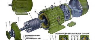
Design features
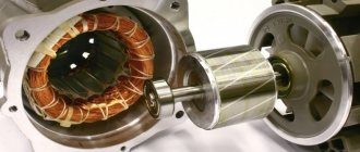
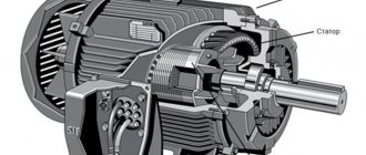
Knowledge of the design features of any equipment greatly facilitates the purchase and subsequent work with it, including the operation and repair of an asynchronous motor with a wound rotor. First of all, you should remember that all electric motors are designed according to a similar principle - they necessarily have a stationary stator and a movable rotor that carries out rotational movements inside the power unit. The stator of an asynchronous motor with a wound rotor has windings connected to the AC mains, the voltage on which interacts with the rotor windings. This connection is explained by the principles of magnetic flux.
The usual design of the stator of an asynchronous motor is an electric motor housing with a core pressed inside. The core winding is divided into several sectors enclosed in coils. Cables with protective insulation are removed from these windings, preventing their mutual short circuit. The rotor is made of a shaft and an assembled lamellar core. Typically, plates with standard size symmetrical grooves made of high-tech steel are used here. During operation of the rotor shaft, torque is transmitted to the drive of the electrical installation.
A drawing of an asynchronous motor with its main components looks like this:
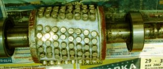
The most common are two types of rotors:
- Short-circuited.
- Phase.
The first option, as part of its design, has aluminum rods passing through the core and closed by end rings. This is the so-called “squirrel wheel”. To increase the strength of the grooves, they are also often treated with an aluminum compound. The design of a wound rotor is somewhat different from that of a squirrel-cage rotor. Here, the number of coils installed at a certain angle directly depends on the number of paired poles, in many cases comparable to the paired poles found on the stator.
The principle of operation of an electric motor with a wound rotor
Now let's take a closer look at the principle of operation of an asynchronous motor with a phase rotor and its connection. Here we can distinguish a sequence of five important stages:
- the first stage - the stator, which has a triple winding, receives voltage from a three-phase AC power supply with the required parameters;
- second stage – a magnetic field is formed, driving the rotor;
- third stage - the rotor gradually accelerates, and its speed increases significantly;
- fourth stage - when the stator and rotor field lines reach a certain value and intersect, an electromotive force arises, acting on the rotor winding and creating an electric current on it;
- fifth stage - the stator and rotor magnetic fields begin to actively interact with each other, maintaining the torque of the shaft.
Next, the asynchronous motor with a phase-type rotor is controlled in normal mode. The operating principle of an asynchronous motor with a wound rotor differs from the squirrel-cage version by the presence of a full three-phase winding with a similar arrangement on the stator and rotor parts.
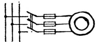
A typical control circuit for an asynchronous motor with a wound rotor looks like this:
The control diagram of an asynchronous motor with a wound rotor shows that the rotor winding leads are connected to slip rings mounted on the electric motor shaft. These rings have protective insulation, both among themselves and at the points of contact with the shaft. For each of the phases, of which there are usually three, the rotor has its own separate winding. The starting circuit for these windings most often has the form of a “Star”.
A control rheostat is mounted to the rotor winding, coupled with brushes and slip rings. Despite the apparent complexity of such a design and a more careful calculation of an asynchronous motor, the possibilities for adjusting the operating torque on the shaft are an order of magnitude greater than for motors with a squirrel-cage rotor, the control and use of which is usually associated with the need to use a frequency converter or a special speed controller.
The stator winding is created taking into account the number of coils and poles, of which there should be the same number on the stator and rotor. The stator coils shift between each other by a certain number of degrees. Adjustment of the action of an asynchronous motor with a wound rotor is carried out by changing the current in the rotor windings. This allows you to control the size of the slide and the operating torque of the electric motor. To reduce wear on the rings and brushes during the complete removal of the rheostat, they are usually closed using a special device for lifting the brushes
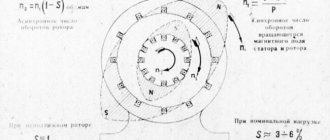
Calculation of the number of repetitions
Let's take m1 - the process of repeating the constant field of magnets and the rotor. The AC phase system forms a rotating magnetic field.
Calculation data is calculated using the formula:
f1 – frequency of electricity$
p – the number of pole pairs of each stator winding.
m2 – the process of repeating the rotation of the rotor. Having a different number of simultaneous repetitions, a given frequency rate will be asynchronous. The frequency calculation is determined by the relationship between the data:
An asynchronous electric motor operates only at asynchronous frequency.
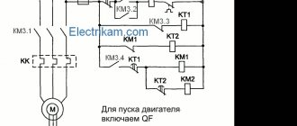
(m2 Rheostat start
Often rheostats provide the necessary effect to turn on the engine of powerless starting torques. Diagram of the rheostat method:
The main characteristic of the method is the connection of the engine to rheostats when starting. The rheostats break (in the drawing K1), and a partial electric current flows through them. This makes it possible to reduce inrush currents. The starting torque is also reduced. The advantage of the rheostatic method is to reduce the load on the mechanical part and the lack of voltage.
Advantages and disadvantages of electric motors with a wound rotor
Nowadays, asynchronous power units are widely used both in everyday life and in production. This popularity is due to a large number of advantages that expand their functionality and purpose.
Among the main advantages of asynchronous motors with a phase-type rotor are:
- high starting torque;
- resistance to mechanical overloads without a significant decrease in efficiency, as well as without reducing the efficiency and stability of the electrical installation (the operating speed of even a heavily loaded unit remains within the permissible norm);
- low starting current;
- possibility of working in fully automatic mode;
- simple and intuitive start-up scheme;
- affordable price;
- absence of additional working and expensive installation equipment.
Despite all the numerous advantages, one cannot fail to note the disadvantages of an asynchronous motor with this design. The main one is the rather large overall dimensions of the unit, which complicates the installation process, further operation and repair of an asynchronous motor with a wound rotor. In addition, such electric motors are often inferior in productivity and efficiency to similar power units with a squirrel-cage rotor.