- home
- >Manufacture of generators
>
some introductory information on converting asynchronous motors into a generator
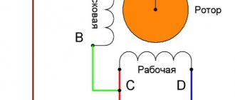
Converting an asynchronous motor is a fairly popular method of making a generator for a wind generator. Asynchronous motors with a small number of poles are designed for high speeds, for example, two-pole motors at 3000 rpm, but wind generators require low speeds, so you need to choose the lowest speed motors. Now the lowest speed ones are available at 750 and 1000 rpm, respectively at 8 and 6 poles.
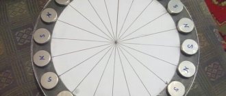
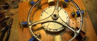
Motors with 2-4 poles have to be rewound to increase the number of poles, this is quite difficult and expensive, but motors with 6-8 poles can not be rewound and can be used as is. The entire conversion of an engine into a generator consists of converting the rotor to neodymium magnets. This is done quite simply, the original rotor is simply ground to the thickness of the magnets (for example, 5 mm), then the rotor is divided by the number of poles (for example, magnets are glued to the poles.
Magnets are selected in small sizes and poles are assembled from them. For example, the AIR112MB8 3 kW engine has a rotor with a diameter of 131 mm and a length of 130 mm. This means the length of the rotor circumference is (130 mm*3.14=408.2 mm), but we grind the rotor by 5 mm, which means (130 mm-10 mm*3.14=376.8 mm) divided by the number of poles (376.8:8= 47.1 mm) and we get a pole width of 47.1 mm. Let’s take magnets 30*10*5 mm, 4 rows of them will fit in a pole and there will be a gap of 7 mm between the poles. The length of the rotor is 130 mm, and we just have 4 magnets with a length of 120 mm, and it turns out that the rotor needs 16 magnets per pole, and in total you will need 128 magnets.
You can use magnets of any other convenient size for a set of poles. The magnets are glued with super glue and other adhesives, and after gluing, the rotor is wrapped with tape and filled with epoxy resin. To use magnets most effectively, you need to make a minimum gap between the magnets and the stator, then the diameter of the rotor with magnets is made to match the diameter of the stator so that it does not extend into the stator by a millimeter. After gluing and filling the magnets, the rotor is adjusted into the stator by grinding the magnets, ground off a little at a time and tried to be inserted into the stator, ensuring that the magnets are as close as possible to the stator teeth and at the same time the rotor rotates freely without snags on the stator. When grinding, it is very important not to overheat the magnets; you can grind on a grinder with water, or on a lathe.
>
In general, it is advisable to make a new all-metal rotor for magnets, or to put a metal sleeve on the original rotor of an asynchronous machine under magnets. This way the magnets will work much more efficiently, and a thickness of 3-4 mm will be enough, and if you do not install a sleeve, then it is advisable to install thicker magnets, for example 6-10 mm.
Below is data on asynchronous motors
, dimensions, thickness of the winding wire, number of poles, winding resistance, etc. The same is true for calculating the power of a converted generator at various speeds when running on 12/24/48 volt batteries. I took the magnetic induction equal to 1 Tesla as the basis for the calculation, but in practice it can be more or less, it all depends on the thickness of the magnets and the filling density of the poles. If the original rotor is machined without a metal sleeve, then with a magnet thickness of 5 mm n50 grade, the magnetic induction will be approximately 0.8 Tesla; if the magnets are 8-10 mm thick, then the magnetic induction will be 1-1.2 Tesla. And if with a sleeve or with an all-metal rotor, then with a magnet thickness of 5-6 mm, the magnetic induction will be about 1-1.2 Tesla
Asynchronous motor AIR100L6 2.2 kW
Number of poles 6, 1000 rpm. Stator dimensions:
outer diameter 168 mm, inner diameter 113 mm, stator length 120 mm, number of teeth 36.
Winding:
number of conductors in the groove 42, wire diameter 1.13 mm, three-phase, phase resistance 2.39 Ohm.
Approximate power per battery 12/24/48 volts with a delta connection
| Revolutions (rpm) | Voltage XX | Battery 13 V A/Watt*h | Battery 26 V A/Watt*h | Battery 52 V A/Watt*h |
| 60 | 13 | — | — | — |
| 120 | 26 | 5,4/70 | — | — |
| 180 | 39 | 10.8/140 | 5,4/140 | — |
| 240 | 52 | 16.2/211 | 10,8/281 | — |
| 300 | 65 | 21.6/281 | 16.2/422 | 4,5/247 |
| 360 | 78 | 27/352 | 21/563 | 10/540 |
| 420 | 91 | 32.5/422 | 27/704 | 15/832 |
| 600 | 130 | 48/633 | 43/1126 | 31/1710 |
| 900 | 195 | 75/985 | 70/1830 | 58/3172 |
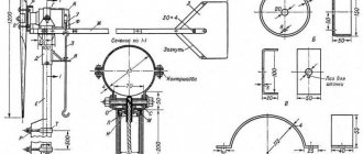
Assembly instructions from a car generator
To do this, you will need to prepare all the components in advance. The most important element is the generator. It is best to take a tractor or bus, it can generate much more energy. But if this is not possible, then it is more likely to make do with weaker units. To assemble the device you will need: • voltmeter • battery charging relay • steel for making blades • 12 volt battery • box for wires • 4 bolts with nuts and washers • clamps for fastening
Asynchronous motor AIR100L8 1.5 kW
Number of poles 8, 750 rpm. Stator dimensions:
outer diameter 168 mm, inner diameter 117 mm, stator length 120 mm, number of teeth 48.
Winding:
number of conductors in the groove 48, wire diameter 1.01 mm, three-phase, phase resistance 3.7 Ohm.
Approximate power per battery 12/24/48 volts with a delta connection
| Revolutions (rpm) | Voltage XX | Battery 13 V A/Watt*h | Battery 26 V A/Watt*h | Battery 52 V A/Watt*h |
| 60 | 17 | 1/13 | — | — |
| 120 | 34 | 5,6/73 | 2/56 | — |
| 180 | 51 | 10/130 | 6.7/175 | — |
| 240 | 68 | 14.8/193 | 11,3/295 | 4,3/244 |
| 300 | 95 | 22/288 | 18.6/484 | 11.6/604 |
| 360 | 112 | 26.7/347 | 23.2/604 | 16.2/843 |
| 420 | 129 | 31/407 | 27.8/723 | 20.8/1082 |
| 600 | 170 | 42.4/551 | 38.9/1011 | 31.8/1658 |
| 900 | 255 | 65.4/850 | 61.8/1609 | 54/2852 |
Asynchronous motor AIR112MA6 3 kW
Number of poles 6, 1000 rpm. Stator dimensions:
outer diameter 191 mm, inner diameter 132 mm, stator length 100 mm, number of teeth 54.
Winding:
number of conductors in the groove 28, wire diameter 1.19 mm, three-phase, phase resistance 2 Ohms.
Approximate power per battery 12/24/48 volts with a delta connection
| Revolutions (rpm) | Voltage XX | Battery 13 V A/Watt*h | Battery 26 V A/Watt*h | Battery 52 V A/Watt*h |
| 60 | 13 | — | — | |
| 90 | 19 | 3/39 | — | — |
| 120 | 26 | 6.5/84 | — | — |
| 180 | 39 | 13/169 | 6.5/169 | — |
| 240 | 52 | 19.5/253 | 13/338 | — |
| 300 | 65 | 26/338 | 19.5/507 | 6.5/338 |
| 360 | 78 | 32.5/422 | 26/676 | 13/676 |
| 420 | 91 | 39/507 | 32.5/845 | 19.5/1014 |
| 600 | 130 | 58.5/760 | 52/1352 | 31.8/39/2028 |
Ideal windmill theory
This theory was developed at different times by scientists and specialists in the field of mechanics. It was first developed by V.P. Vetchinkin in 1914, and the theory of an ideal propeller was used as a basis. In these studies, the wind energy utilization factor of an ideal wind turbine was derived for the first time.
Work in this area was continued by N.E. Zhukovsky, who derived the maximum value of this coefficient equal to 0.593. In the later works of another professor - Sabinin G.Kh. the adjusted coefficient value was 0.687.
In accordance with the developed theories, an ideal wind wheel should have the following parameters:
- The axis of rotation of the wheel must be parallel to the speed of the wind flow.
- The number of blades is infinitely large, with a very small width.
- Zero value of wing profile drag in the presence of constant circulation along the blades.
- The entire swept surface of the windmill has a constant lost speed of air flow on the wheel.
- The tendency of angular velocity to infinity.
Asynchronous motor AIR112MA8 2.2 kW
Number of poles 8, 750 rpm. Stator dimensions:
outer diameter 191 mm, inner diameter 132 mm, stator length 100 mm, number of teeth 48.
Winding:
number of conductors in the groove 40, wire diameter 1.13 mm, three-phase, phase resistance 2.6 Ohm.
Approximate power per battery 12/24/48 volts with a delta connection
| Revolutions (rpm) | Voltage XX | Battery 13 V A/Watt*h | Battery 26 V A/Watt*h | Battery 52 V A/Watt*h |
| 60 | 17 | 1.5/20 | — | — |
| 90 | 34 | 8/105 | 3/80 | — |
| 120 | 51 | 14.6/190 | 9.6/250 | — |
| 180 | 68 | 31/275 | 16/420 | 6.1/320 |
| 240 | 85 | 27/360 | 22.6/590 | 12.6/550 |
| 300 | 112 | 38/495 | 33/860 | 23/1200 |
| 360 | 129 | 44.6/579 | 39.6/1030 | 29.6/1540 |
| 420 | 146 | 51/665 | 46/1200 | 36/1880 |
| 600 | 163 | 57.6/750 | 52.6/1370 | 42.6/2220 |
Testing a homemade device
Testing of the finished wind generator should be carried out with the structure fully assembled, installed and securely fastened. The temptation to try a windmill in action is great and often forces people to take ill-considered actions, resulting in breakdowns, destruction, and injuries.
The functionality of individual components (for example, a generator) can be checked using an electric drill with adjustable rotation speed. The capabilities of a wind turbine can also be tested separately, without connecting a generator, to obtain data on its performance without load. All other tests or samples require high-quality assembly or connection in accordance with all the rules.
Asynchronous motor AIR112MB8 3 kW
Number of poles 8, 750 rpm. Stator dimensions:
outer diameter 191 mm, inner diameter 132 mm, stator length 130 mm, number of teeth 48.
Winding:
number of conductors in the groove 31, wire diameter 1.25 mm, three-phase, phase resistance 1.93 Ohm.
Approximate power per battery 12/24/48 volts with a delta connection
| Revolutions (rpm) | Voltage XX | Battery 13 V A/Watt*h | Battery 26 V A/Watt*h | Battery 52 V A/Watt*h |
| 60 | 17 | 2/26 | — | — |
| 90 | 34 | 11/143 | 4.2/109 | — |
| 120 | 51 | 20/260 | 13.1/242 | — |
| 180 | 68 | 28.9/376 | 22.1/574 | 8.4/437 |
| 240 | 85 | 37.8/492 | 31/807 | 17.3/903 |
| 300 | 112 | 52.1/677 | 45.2/1176 | 31.5/1642 |
| 360 | 129 | 61/793 | 54.2/1409 | 40.5/2107 |
| 420 | 146 | 70/910 | 63.1/1642 | 49.4/2572 |
| 600 | 163 | 78.9/1026 | 72.1/1874 | 58.4/3037 |
Asynchronous motor AIR132S6 5.5 kW
Number of poles 6, 1000 rpm. Stator dimensions:
outer diameter 225 mm, inner diameter 154 mm, stator length 115 mm, number of teeth 54.
Winding:
number of conductors in the groove 21, wire diameter 1.13 mm, three-phase, phase resistance 1 Ohm.
Approximate power per battery 12/24/48 volts with a delta connection
| Revolutions (rpm) | Voltage XX | Battery 13 V A/Watt*h | Battery 26 V A/Watt*h | Battery 52 V A/Watt*h |
| 60 | 13 | — | — | |
| 90 | 19 | 6/78 | — | — |
| 120 | 26 | 13/169 | — | — |
| 180 | 39 | 26/338 | 13/338 | — |
| 240 | 52 | 39/507 | 26/676 | — |
| 300 | 65 | 52/676 | 39/1014 | 13/676 |
| 360 | 78 | 65/845 | 52/1352 | 26/1352 |
| 420 | 91 | 78/1014 | 65/1690 | 39/2028 |
| 600 | 130 | 117/1521 | 104/2704 | 78/4056 |
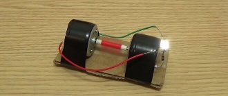
Making your own homemade wind blower from a stepper motor
Stepper motors are used in many electromechanical devices, such as printers. If you start to rotate the shaft of such an engine, electrical voltage will appear at its terminals. This means that the stepper motor can be used as an electric generator.
What to prepare for work
Before you start, you should get a small stepper motor, for example from a printer. Prepare electronic components and wires in order to assemble the rectifier circuit. You will need to cut thin sheet steel or aluminum to create the structure. And definitely - small fasteners. All you need is a simple plumbing tool and a soldering iron.
Drawings and sketches
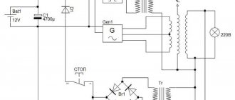
The design part can be presented in the form of sketches. The electric motor is installed on a plywood plate along the mounting holes on the motor body. The rectifier circuit is shown in the figure below.
PHOTO: YouTube.com Electrical circuit of a rectifier for a generator from a stepper motor
Manufacturing technology
Screw the engine to the plywood plate. To increase its speed and obtain increased voltage, you can make a gearbox that increases the speed. To do this, having carefully determined the center-to-center distance and selected the tooth parameters, you need to install a larger diameter gear on the same base plate on the axis.
PHOTO: YouTube.com Speed increasing gearbox
The handle on the drive gear is needed for testing work and for generating current during urgent charging of microbatteries.
PHOTO: YouTube.comAssembled device to test its operation
PHOTO: YouTube.com A motor-generator and a rectifier unit are installed on the board
Functionality check
To check the functionality of the finished device, a USB tester is connected to it. When you rotate the knob, the value of the electrical voltage appears on the tester monitor.
PHOTO: YouTube.comChecking the device's functionality
To operate as a wind generator, an impeller should be placed on the motor shaft.
Asynchronous motor AIR132S8 4 kW
Number of poles 8, 750 rpm. Stator dimensions:
outer diameter 222 mm, inner diameter 158 mm, stator length 112 mm, number of teeth 48.
Winding:
number of conductors in the groove 28, wire diameter 1.48 mm, three-phase, phase resistance 1.24 Ohm.
Approximate power per battery 12/24/48 volts with a delta connection
| Revolutions (rpm) | Voltage XX | Battery 13 V A/Watt*h | Battery 26 V A/Watt*h | Battery 52 V A/Watt*h |
| 60 | 17 | 3,2/41 | — | — |
| 90 | 34 | 16.9/220 | 6,4/127 | — |
| 120 | 51 | 30.6/398 | 20/524 | — |
| 180 | 68 | 44.3/526 | 33.8/880 | 12.9/670 |
| 240 | 85 | 58/754 | 47.5/1237 | 26.6/1383 |
| 300 | 112 | 79.8/1037 | 69.3/1803 | 48.3/2516 |
| 360 | 129 | 93.5/1216 | 83/2159 | 62/3229 |
| 420 | 146 | 120/1572 | 96.7/2516 | 75.8/3941 |
| 600 | 163 | 57.6/750 | 110/2872 | 89.5/4654 |
There is no point in calculating a lot of motors; I think the information presented above is enough to understand what will happen from an asynchronous motor of various sizes. I think that it is quite possible to convert four-pole magnets into magnets, and even two-pole ones, but the power will be lower. I also calculated the power when connecting the phases in a triangle since with such a connection the generator resistance is lower and therefore the charging current is higher. But you can also connect it with a star, the voltage will rise 1.7 times higher, but so will the resistance, but charging will begin at even lower speeds.
Low-power asynchronous motors from 0.18 to 1 kW without stator rewinding are not suitable for wind generators; of course they will provide energy, but due to the high resistance of the windings, the charging current will be very small. For example, a 6-pole motor with a power of 0.55 kW has a phase resistance of 22 Ohm, and at 600 rpm the power will be only (130-13:22 = 5.3 * 13 = 69) 69 watts on a 12-volt battery, and at 48 volts about 180 watts.
The screw for the generator can be designed and made from PVC pipes, or made from wood. The mmka program for calculating blades is described in this article - Calculation of blades for a wind generator
Wind generator characteristics
First you need to decide on the desired final result. The characteristics of the electric motor that acts as a generator can be different, and this determines how much electricity the device will generate per unit of time.
To produce an average amount of energy, the generator must have approximately the following characteristics:
- The minimum installation power is 1.3 kW.
- Neodymium magnets in the design are desirable. Their function is to provide electromagnetic driving force. For this purpose, a steel sleeve can be used, which is installed on the rotor.
- The location of the magnets on the rotor must correspond to the diagram. This means that their poles must be turned in the correct direction.
- The rotor shaft must first be ground and adjusted to the diameter of the magnets.
- When installing magnets, it is not always necessary to redo the winding. If it consists of wires with a large cross-section, it’s okay, it will only increase the power. The best winding option would be a device with six poles, a wire with a cross-section of no more than 1.2 mm and a maximum of 24 turns on the coil.
You might be interested in Features of an electrical energy generator