Magnetism and electricity
The dictionary definitions of electricity and magnetism are different, although they are manifestations of the same force. When electric charges move, they create a magnetic field. Its change, in turn, leads to the generation of electric current.
Inventors use electromagnetic forces to create electric motors, generators, MRI machines, levitating toys, consumer electronics and many other invaluable devices without which it is impossible to imagine the daily life of a modern person. Electromagnets are inextricably linked with electricity; they simply cannot work without an external power source.
Electromagnets and their applications
Pay attention to the direction of the electric current in the coil. According to the right-hand rule, electric current creates a magnetic field, the lines of force of which are directed in the same way as those of a magnet. Thus, we can assign magnetic poles to a coil carrying an electric current, just like a magnet. Therefore, such a coil with electric current can be called an electromagnet.
Important! A coil with an iron core inside is called an electromagnet.
Electromagnets are more widely used in technology than permanent magnets. This happens mainly for two reasons:
- They create a stronger magnetic field because we can use a ferromagnetic core in them, which will amplify the magnetic field created by the electric current flowing in the coil by 1000 times.
- You can control them - increase or decrease the induction value, because it is directly proportional to the electric current flowing in the winding.
Let us note the widespread use of electromagnets, which are used, for example, in:
- electrical machines (motors and generators);
- loudspeakers, relays, contactors, etc.;
- magnetic railways;
- devices using nuclear magnetic resonance (MRI). The main part of the MRI is a superconducting electromagnet, which generates a very strong magnetic field with induction = 3 Tesla. The patient to be tested is placed inside this electromagnet;
- electromagnetic cranes (steel mills, shipyards, workshops);
- circular accelerators (for example, at CERN, where a superconducting electromagnet operates);
- locks for gates and doors.
Of course, not in all applications the electromagnet resembles a so-called bar magnet; very often it resembles a horseshoe magnet. For example, an electromagnet used to lift scrap iron, the model of which is shown in Fig. 8. or an electromagnet, which is used for an electric bell (Fig. 9.).
Rice. 8. Electromagnet for lifting scrap metal
Rice. 9. Electromagnet in the circuit of a traditional electric bell. Source Wikipidia
Finally, an interesting fact. You can go even further and connect both ends of the coil. Then we get a so-called toroidal coil (see Fig. 10). It is an important component of AC electrical systems; it serves to store the energy of the magnetic field and can have a high inductance (L).
Rice. 10. Toroidal coil. Source: Freepik license
Definition
An electromagnet is a special device whose operation creates a magnetic field when an electric current is applied to it. Most often, electromagnets consist of a primary winding and a core, which has ferromagnetic properties.
The winding is usually made of copper or aluminum wire of varying thickness, always covered with insulation. But there are also electromagnets made of superconducting materials. The magnetic cores themselves are made of steel, iron-nickel alloys or cast iron. And in order to minimize losses due to eddy currents, magnetic cores are structurally made from a whole set of thin sheets. Now we know what an electromagnet is. Let's take a closer look at the history of the creation of this useful device.
How to make a homemade electromagnet
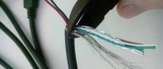
This video from the Kreosan channel shows how to make your own electric magnet. You need to take the transformer from the microwave, cut it and remove the windings. Other transformers will also work. But powerful and available only in microwaves.
We need a primary winding. We just turned it on, and it’s already starting to vibrate. What will happen when it attracts iron? It's time to try out the electromagnet. It can be supplied with 12, 24, 36, 48, 110, 220 volts. In this case, there can be direct and alternating current. Let's turn on the laptop battery and see what a homemade electromagnet can do at a voltage of 12 volts. We take a nut and, with the participation of an electromagnet, crush it with a door. As you can see, he easily dealt with the nut. Let's try to lift something heavier. For example, a manhole cover.
There is an idea for a simple pulsation meter.
The simplest electromagnet in 5 minutes
Further. Another channel (HM Show) released a video on the same topic. It showed how to make a simple electromagnet in 5 minutes. To make a device with your own hands, you will need a steel rod, copper wire and any insulating material.
First, we insulate the steel rod with construction tape and cut off the excess material. It is necessary to wrap the copper wire around the insulating material so that there are as few air gaps as possible. The strength of the magnet depends on this, as well as the thickness of the copper wire, the number of turns and the current strength. These indicators need to be selected experimentally. After winding the wire, wrap it with insulating material.
We strip the ends of the wire. We connect the magnet to the power supply and apply a voltage of four volts with a current of 1 ampere. As you can see, the bolts do not magnetize well. To strengthen the magnet, we increase the current to 1.9 amperes and the result immediately changes for the better! With this current strength we can now lift not only bolts, but also wire cutters and pliers. Try making it using a battery, and write the result in the comments.
izobreteniya.net
Story
William Sturgeon is considered the creator of the electromagnet. It was he who made the first such magnet in 1825. Structurally, the device was a cylindrical piece of iron, around which a thick insulated copper wire was wound. At the moment when an electric current was passed through it, the metal rod acquired the properties of a magnet. And when the flow of current was interrupted, the device immediately lost all magnetism. It is precisely this quality - turning on and off when necessary - that allows the use of electromagnets in a number of technological and industrial fields.
We looked at the question of what an electromagnet is. Now let's look at its main types. They are divided depending on the method of creating the magnetic field. But their function remains the same.
How to make an electromagnet with your own hands at home
Such a device is convenient because its operation is easy to control using electric current - changing the poles, changing the force of attraction. In some matters it becomes truly indispensable, and is often used as a constructive element of various homemade products. It’s not difficult to make a simple electromagnet with your own hands, especially since almost everything you need can be found in every home.
What you will need
- Any suitable sample made of iron (it is highly magnetic). This will be the core of the electromagnet.
- The wire is copper, always with insulation to prevent direct contact of the two metals. For a homemade electric magnet, the recommended cross-section is 0.5 (but not more than 1.0).
- DC source - battery, battery, power supply.
Additionally:
- Connecting wires for connecting an electromagnet.
- Soldering iron or electrical tape to secure contacts.
This is a general recommendation since the electromagnet is made for a specific purpose. Based on this, the components of the circuit are selected. And if it is done at home, then there cannot be any standard - whatever is at hand will do. For example, in relation to the first point, a nail, a lock shackle, or a piece of iron rod are often used as a core - the choice of options is huge.
Manufacturing procedure
Winding
The copper wire is carefully wound onto the core, turn by turn. With such scrupulousness, the efficiency of the electromagnet will be the maximum possible. After the first “pass” along the iron sample, the wire is laid in a second layer, sometimes a third. It depends on how much power the device requires. But the direction of winding must remain unchanged, otherwise the magnetic field will become “unbalanced”, and the electromagnet will hardly be able to attract anything to itself.
To understand the meaning of the ongoing processes, it is enough to remember the physics lessons from the high school course - moving electrons, the EMF they create, the direction of its rotation.
After winding is completed, the wire is cut so that the leads can be conveniently connected to the power source. If it's a battery, then directly. When using a power supply, battery or other device, you will need connecting wires.
What to consider
There are certain difficulties with the number of layers.
- As turns increase, reactance increases. This means that the current strength will begin to decrease, and the attraction will become weaker.
- On the other hand, increasing the current rating will cause the winding to heat up.
That is why you should not rely on third-party advice from “experienced and experienced” people. There is a specific core (with its own magnetic conductivity, dimensions, cross-section), wire and power source. Therefore, you will have to experiment, achieving the optimal combination of parameters such as current, resistance and temperature.
The operating principle of the electromagnet is described in detail in the following video:
Connection
- Cleaning the copper terminals. The wire is initially coated with several layers of varnish (depending on the brand), and it is known to be an insulator.
- Soldering copper and connecting wires. Although this is not essential, you can twist it by insulating it with a PVC pipe or adhesive tape.
- Fixing the second ends of the wires on the clamps. For example, the “crocodile” type. Such removable contacts will allow you to easily change the poles of the electromagnet, if necessary during its use.
- To make a powerful electromagnet, home craftsmen often use a coil from an MP (magnetic starter), relays, or contactors. They are available for both 220 and 380 V.
It is not difficult to select an iron core based on its internal cross-section. For ease of control, you need to include a rheostat (variable resistance) in the circuit. Accordingly, such an electric magnet is already connected to the outlet. The force of attraction is regulated by changing the R chain.
- You can increase the power of an electromagnet by increasing the cross-section of the core. But only up to certain limits. And here you have to experiment.
- Before making an electric magnet, you need to make sure that the selected iron sample is suitable for this. The check is quite simple. Take a regular magnet; There are a lot of things in the house on such “suction cups”. If it attracts the part selected for the core, it can be used. If the result is negative or “weak,” it is better to look for another sample.
Making an electromagnet is quite simple. Everything else depends on the patience and ingenuity of the master. You may have to experiment to get what you need - with the supply voltage, wire cross-section, and so on. Any homemade product requires not only a creative approach, but also time. If you do not regret it, then an excellent result is guaranteed.
electroadvice.ru
Regardless of why a person needs a magnet, it can easily be made at home. When you have such a thing at hand, you can use it not only to have fun picking up various small pieces of iron from the table, but also to find a useful use for it, for example, to find a needle dropped on the carpet. In this article you will learn how easy it is to make an electromagnet with your own hands at home.
A little physics
As we remember (or don’t remember) from physics lessons, in order to convert electric current into a magnetic field, we need to create induction. Inductance is created using an ordinary coil, inside which this field arises and is transmitted to the steel core around which the coil is wound.
Thus, depending on the polarity, one end of the core will emit a field with a minus sign, and the opposite end will emit a field with a plus sign. But visual magnetic abilities are not affected in any way by polarity. So, when you are done with physics, you can begin decisive action to create a simple electromagnet with your own hands.
Materials for making the simplest magnet
First of all, we need any inductor with a copper wire wound around the core. This can be a regular transformer from any power supply. An excellent way to create electromagnets is to wind them around the narrowed back of picture tubes of old monitors or televisions. The conductor threads in transformers are protected by insulation consisting of an almost invisible layer of special varnish that prevents the passage of electric current, which is exactly what we need. In addition to the indicated conductors, to create an electromagnet with your own hands you also need to prepare:
- A regular one and a half volt battery.
- Scotch tape or tape.
- Sharp knife.
- Hundreds of nails.
The process of making a simple magnet
We start by removing the wires from the transformer. As a rule, its middle is located inside the steel frame. You can, after removing the surface insulation on the coil, simply unwind the wire, dragging it between the frames and the coil. Since we don't need a lot of wire, this method is the most acceptable here. When we have released enough wire, we do the following:
- We wind the wire removed from the transformer coil around a nail, which will serve as a steel core for our electromagnet. It is advisable to make turns as often as possible, pressing them tightly against each other. Do not forget to leave a long end of the wire at the initial turn, through which our electromagnet will be powered to one of the poles of the battery.
- When we reach the opposite end of the nail, we also leave a long conductor for powering. We cut off the excess wire with a knife. To prevent the spiral we wound from unraveling, you can wrap it with tape or tape.
- We strip both ends of the wire coming from the wound nail from the insulating varnish with a knife.
- We lean one end of the stripped conductor against the positive of the battery and secure it with tape or tape so that the contact is well maintained.
- We wind the other end to the minus in the same way.
The electromagnet is ready for use. By scattering metal clips or tacks on the table, you can check its functionality.
How to make a more powerful magnet?
How to make an electromagnet with more powerful magnetic properties with your own hands? The strength of magnetism is influenced by several factors, and the most important one is the electrical current of the battery we use. For example, by making an electromagnet from a square 4.5 volt battery, we will triple the strength of its magnetic properties. The 9-volt crown will give an even more powerful effect.
But do not forget that the stronger the electric current, the more turns will be required, since the resistance with a small number of turns will be too strong, which will lead to strong heating of the conductors. If they are heated too much, the insulating varnish may begin to melt, and the turns will begin to short-circuit to each other or to the steel core. Both will sooner or later lead to a short circuit.
Also, the strength of magnetism depends on the number of turns around the magnet core. The more there are, the stronger the induction field will be, and the stronger the magnet will be.
Making a more powerful magnet
Let's try to make a 12 volt electromagnet with our own hands. It will be powered by a 12-volt AC power supply or a 12-volt car battery. To manufacture it, we will need a much larger amount of copper conductor, and therefore we should initially remove the internal coil with copper wire from the prepared transformer. A grinder is the best way to extract it.
What we need for production:
- A steel horseshoe from a large padlock, which will serve as our core. In this case, it will be possible to magnetize the pieces of iron at both ends, which will further increase the lifting capacity of the magnet.
- Coil with copper wire in varnished insulation.
- Insulating tape.
- Unnecessary 12 volt power supply or car battery.
The process of making a powerful 12-volt magnet
Of course, any other massive steel pin can be used as a core. But a horseshoe from an old castle will do just fine. Its bend will serve as a kind of handle if we start lifting loads of impressive weight. So, in this case, the process of making an electromagnet with your own hands is as follows:
- We wind the wire from the transformer around one of the horseshoes. We place the coils as tightly as possible. The curve of the horseshoe will interfere a little, but that's okay. When the length of the side of the horseshoe ends, we lay the turns in the opposite direction, on top of the first row of turns. We make a total of 500 turns.
- When the winding of one half of the horseshoe is ready, wrap it with one layer of electrical tape. The original end of the wire, intended for recharge from a current source, is brought out to the upper part of the future handle. We wrap our coil on the horseshoe with another layer of electrical tape. We wind the other end of the conductor to the bending core of the handle and make another coil on the other side.
- We wind the wire on the opposite side of the horseshoe. We do everything the same as in the case of the first side. When 500 turns have been laid, we also remove the end of the wire for power supply from an energy source. For those who don't understand, the procedure is clearly shown in this video.
The final stage of making an electromagnet with your own hands is recharging to the energy source. If it is a battery, we extend the ends of the stripped conductors of our electromagnet using additional wires, which we connect to the battery terminals. If this is a power supply, cut off the plug going to the consumer, strip the wires and screw a wire from the electromagnet to each one. Insulate with electrical tape. We plug the power supply into the outlet. Congratulations. You have made with your own hands a powerful 12-volt electromagnet that is capable of lifting loads over 5 kg.
An electromagnet is an artificial magnet in which a magnetic field arises and is concentrated in a ferromagnetic core as a result of the passage of electric current through the winding surrounding it, i.e. When current is passed through the coil, the core placed inside it acquires the properties of a natural magnet.
The scope of application of electromagnets is very wide. They are used in electrical machines and devices, in automation devices, in medicine, and in various types of scientific research. Most often, electromagnets and solenoids are used to move some mechanisms, and in industries to lift loads.
For example, a lifting electromagnet is a very convenient, productive and economical mechanism: no maintenance personnel are required to secure and release the transported cargo. It is enough to place an electromagnet on the moving load and turn on the electric current in the electromagnet coil and the load will be attracted to the electromagnet, and to release the load you only need to turn off the current.
The design of an electromagnet is easy to replicate and is essentially nothing more than a core and a coil of conductor. In this article we will answer the question of how to make an electromagnet with your own hands?
How an electromagnet works (theory)
If an electric current flows through a conductor, a magnetic field is formed around this conductor. Since current can only flow when the circuit is closed, the conductor must be a closed loop, such as a circle, which is the simplest closed loop.
Previously, a conductor rolled into a circle was often used to observe the effect of current on a magnetic needle placed in its center. In this case, the arrow is at an equal distance from all parts of the conductor, making it easier to observe the effect of the current on the magnet.
To increase the effect of electric current on a magnet, you can first increase the current. However, if you bend a conductor through which some current flows twice around the circuit it covers, then the effect of the current on the magnet will double.
In this way, this action can be increased many times over by bending the conductor an appropriate number of times around a given circuit. The resulting conducting body, consisting of individual turns, the number of which can be arbitrary, is called a coil.
Let's remember the school physics course, namely that when an electric current flows through a conductor. If the conductor is rolled into a coil, the magnetic induction lines of all turns will add up, and the resulting magnetic field will be stronger than for a single conductor.
The magnetic field generated by electric current, in principle, has no significant differences compared to the magnetic field. If we return to electromagnets, the formula for its traction force looks like this:
F=40550∙B 2 ∙S,
where F is the traction force, kg (force is also measured in newtons, 1 kg = 9.81 N, or 1 N = 0.102 kg); B—induction, T; S is the cross-sectional area of the electromagnet, m2.
That is, the traction force of an electromagnet depends on the magnetic induction, consider its formula:
Here U0 is the magnetic constant (12.5*107 H/m), U is the magnetic permeability of the medium, N/L is the number of turns per unit length of the solenoid, I is the current strength.
It follows that the force with which a magnet attracts something depends on the current strength, the number of turns and the magnetic permeability of the medium. If there is no core in the coil, the medium is air.
Below is a table of relative magnetic permeabilities for different media. We see that for air it is equal to 1, and for other materials it is tens and even hundreds of times greater.
In electrical engineering, a special metal is used for cores; it is often called electrical or transformer steel. In the third line of the table you see “Iron with silicon” whose relative magnetic permeability is 7 * 103 or 7000 H/m.
This is the average value for transformer steel. It differs from the usual one precisely in the silicon content. In practice, its relative magnetic permeability depends on the applied field, but we will not go into details. What does the core do in the coil? An electrical steel core will enhance the magnetic field of the coil by approximately 7000-7500 times!
All you need to remember to begin with is that the material of the core inside the coil depends on it, and the force with which the electromagnet will pull depends on it.
Practice
One of the most popular experiments that are carried out to demonstrate the occurrence of a magnetic field around a conductor is the experiment with metal shavings. The conductor is covered with a sheet of paper and magnetic shavings are poured onto it, then an electric current is passed through the conductor, and the shavings change their location somehow on the sheet. It's almost an electromagnet.
But simply attracting metal shavings is not enough for an electromagnet. Therefore, you need to strengthen it, based on the above - you need to make a coil wound on a metal core. The simplest example would be insulated copper wire wound around a nail or bolt.
Such an electromagnet is capable of attracting various pins, scrapies, and the like.
As a wire, you can use either any wire in PVC or other insulation, or copper wire in varnish insulation such as PEL or PEV, which are used for windings of transformers, speakers, motors, etc. You can find it either new in reels, or reeled from the same transformers.
10 Nuances of making electromagnets in simple words:
1. The insulation along the entire length of the conductor must be uniform and intact so that there are no interturn short circuits.
2. Winding should go in one direction, like on a spool of thread, that is, you cannot bend the wire 180 degrees and go in the opposite direction. This is due to the fact that the resulting magnetic field will be equal to the algebraic sum of the fields of each turn; if you do not go into details, the turns wound in the opposite direction will generate an electromagnetic field of the opposite sign, as a result the fields will be subtracted and as a result the strength of the electromagnet will be less , and if there are the same number of turns in one and the other direction, the magnet will not attract anything at all, since the fields will suppress each other.
3. The strength of the electromagnet will also depend on the strength of the current, and it will depend on the voltage applied to the coil and its resistance. The resistance of the coil depends on the length of the wire (the longer, the larger it is) and its cross-sectional area (the larger the cross-section, the lower the resistance). An approximate calculation can be made using the formula - R=p*L/S
4. If the current is too high, the coil will burn out
5. With direct current, the current will be greater than with alternating current due to the influence of inductance reactance.
6. When operating on alternating current, the electromagnet will hum and rattle, its field will constantly change direction, and its traction force will be less (half) than when operating on constant current. In this case, the core for AC coils is made of thin sheet metal, assembled into a single whole, while the plates are isolated from each other with varnish or a thin layer of scale (oxide), the so-called. charge - to reduce losses and Foucault currents.
7. With the same traction force, an alternating current electric magnet will weigh twice as much, and the dimensions will increase accordingly.
8. But it is worth considering that alternating current electromagnets are faster than direct current magnets.
9. DC electromagnet cores
10. Both types of electromagnets can operate on both direct and alternating current, the only question is what strength it will have, what losses and heating will occur.
3 ideas for an electromagnet using improvised means in practice
As already mentioned, the easiest way to make an electromagnet is to use a metal rod and a copper wire, selecting both for the required power. The supply voltage of this device is selected experimentally based on the current strength and heating of the structure. For convenience, you can use a plastic spool of thread or the like, and select a core - a bolt or nail - for its internal hole.
The second option is to use an almost finished electromagnet. Think about electromagnetic switching devices - relays, magnetic starters and contactors. For use on direct current and 12V voltage, it is convenient to use a coil from automotive relays. All you need to do is remove the case, break out the moving contacts and connect the power.
To operate from 220 or 380 volts, it is convenient to use coils; they are wound on a mandrel and can be easily removed. Select the core based on the cross-sectional area of the hole in the coil.
This way you can turn on the magnet from the outlet, and it is convenient to regulate its strength if you use a rheostat or limit the current using a powerful resistance, for example.
An electromagnet is a very useful device that is widely used in industry and in many areas of human activity. Although this device may seem complex in its design, it is easy to manufacture and a small home electromagnet can be made at home using improvised materials.
Let's watch the process of creating this homemade product in the video:
In order to make a small electromagnet at home we will need:
— Iron nail or bolt; - Copper wire; - Sandpaper; - Alkaline battery.
At the very beginning, it should be noted that it is not advisable to use too thick wire. Copper wire with a diameter of one millimeter is perfect for a future electromagnet. As for the size of the nail or bolt, the ideal length would be 7-10 centimeters.
So, let's start making a mini electromagnet. First we need to wrap the copper wire around the bolt. It is important to pay attention to the fact that each turn fits tightly to the previous one.
You need to wind the wire so that there is a piece of wire left at both ends.
All that remains is to connect our wires to the source, namely the alkaline battery. After this, our bolt will attract metal elements.
The operating principle of an electromagnet is very simple. When an electric current passes through a coil with a core, a magnetic field is formed, which attracts metal elements. The power of the electromagnet depends on the density of the coil and the number of layers of copper wire, as well as on the current strength.
Along with permanent magnets, since the 19th century, people began to actively use variable magnets in technology and everyday life, the operation of which can be regulated by the supply of electric current. Structurally, a simple electromagnet is a coil of electrical insulating material with a wire wound on it. If you have a minimum set of materials and tools, it is not difficult to make an electromagnet yourself. We will tell you how to do it in this article.
When electric current passes through a conductor, a magnetic field appears around the wire; when the current is turned off, the field disappears. To enhance the magnetic properties, a steel core can be introduced into the center of the coil or the current can be increased.
general characteristics
An electromagnet is a simple coil of wire that is connected to a source that transmits direct current.
By connecting to a source of direct current (as well as voltage), the coil and wire begin to receive energy resources and create a magnetic field that is similar to the field that is formed in permanent bar magnets. The density of the magnetic flux is always proportional to the amount of electric current flowing through the thickness of the coil. The polarity of the electromagnet is determined by the direction of the current. The formation mechanism involves (the simplest option) winding a wire around a core made of metal, through which electricity from a certain source is then passed. If the internal cavity of the coil is filled with air, then it is called a solenoid.
An electromagnet is a device through which an electromagnetic field can be created. The main characteristic is his ability to control the strength of a given field, polarity and its shape. In this case, the strength of the magnetic field is controlled by the amount of used electric current that flows through the coil. The polarity can be set by determining in which direction the flowing current should be moved. The shape of the magnetic field depends on the shape of the metal core, which serves as the “rod” for the winding wire. Do not forget that the poles of an electromagnet are determined in the same way as in solenoids, according to the physical rule of the right hand. P.P.R. also called the gimlet rule, which is a mnemonic device by which the direction of vector products and the right basis is determined.
You can increase the strength of an electromagnet, or rather its field, using:
- the use of “soft” iron cores;
- the use of large numbers of turns;
- application of electric current on a large scale.
How to make an electromagnet
An electromagnet, unlike a permanent magnet, acquires its properties only under the influence of electric current. With its help, he changes the force of attraction, the direction of the poles and some other characteristics. Some people who are passionate about mechanics make their own electromagnets to use them in homemade installations, mechanisms and various designs. Making an electromagnet with your own hands is not difficult. Simple devices and available materials are used.
The simplest kit for making an electromagnet
What you will need:
- One iron nail 13-15 cm long or another metal object, which will become the core of the electromagnet.
- About 3 meters of insulated copper wire.
- The power source is a battery or a generator.
- Small wires for connecting the wire to the battery.
- Insulating materials.
If you are using a larger piece of metal to create a magnet, the amount of copper wire must be increased proportionally. Otherwise, the magnetic field will be too weak. It is impossible to answer exactly how many windings will be needed. Usually craftsmen find out this experimentally, increasing and decreasing the amount of wire, while simultaneously measuring changes in the magnetic field. Due to the excess wire, the strength of the magnetic field also becomes weaker.
Step-by-step instruction
By following simple recommendations, you can easily make an electromagnet yourself.
Stripping the ends of the copper wire
Step 1
Strip the insulation from the ends of the copper wire that you will wind around the core. 2-3 cm is enough. They will be needed to connect the copper wire with a regular one, which in turn will be connected to the power source.
Winding the copper wire around the nail
Step 2
Carefully wind the copper wire around the nail or other core so that the turns are parallel to each other. This must be done in only one direction. The location of the poles of the future magnet depends on this. If you want to change their location, you can simply rewind the wire in a different direction. By not fulfilling this condition, you will ensure that the magnetic fields of different sections will influence each other, which is why the magnet strength will be minimal.
Connecting the wire to the battery
Step 3
Connect the ends of the cleaned copper wire to two previously prepared conventional wires. Insulate the connection, and connect one end of the wire to the positive charge terminal on the battery, and the other to the opposite end. Moreover, it does not matter which wire is connected to which end - this will not affect the operational capabilities of the electromagnet. If everything is done correctly, the magnet will start working immediately! If the battery has a reversible connection method, then you can change the direction of the poles.
The electromagnet works!
How to increase the strength of the magnetic field
If the resulting magnet does not seem powerful enough to you, try increasing the number of turns of copper wire. Do not forget that the further the wires are located from the iron core, the less impact they will have on the metal. Another way is to connect a more powerful power source. But even here you need to be careful. Too much current will heat the core. At high temperatures, the insulation melts and the electromagnet can become dangerous.
We connected a powerful power source - the magnet became more powerful.
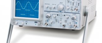
It makes sense to experiment with cores. Take a thicker base - a metal bar 2-3 cm wide. You can find out how powerful the electromagnet is using a special device that measures the strength of the magnetic field. With its help and the method of experimentation, you will find a golden mean in creating an electromagnet.
Main classification
There are three main ways to classify electromagnets. They are determined by the current in electromagnets and the method of its creation:
- Neutral DC e/m is a device in which a magnetic flux is created in such a way that the force of attraction becomes dependent only on the size and speed of supply of direct current, and its direction in the winding does not affect anything.
- Polarized DC e/m is a device in which 2 independent magnetic fluxes are placed: polarizing and working. The second is created using a working winding. Polarizing flows owe their formation to constant magnetic fields, less often to additional electromagnets. These flows are necessary to create attractive forces in the magnet. The activity of such a device is determined by the direction and/or magnitude of the electric current in the winding that performs the work.
- AC electric motor – devices whose windings are powered by an alternating current source. The flow of a magnetic flow can periodically change in its direction and dimension (magnitude). The potential of the unidirectional force responsible for attraction can only change in its magnitude, which leads to a pulsation of this force in the amount from zero to the maximum limit values with a frequency twice as high as the frequency of the feeding current. Most often used in household appliances.
Electromagnet device
A classical electromagnet is a device in which a magnetic field appears when an electric current passes through it. In the simplest electromagnet, such a field can form even around an ordinary conductor if it is energized.
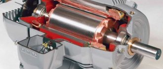
The circuit of the simplest electromagnet includes a ferromagnetic core with a wound winding. When electric current flows through the winding, a powerful magnetic field is formed in the core. To perform mechanical actions, the structure is equipped with a moving part called an anchor. Aluminum or copper insulated wire is used for winding. This circuit diagram is the basis for creating similar electromagnets with your own hands at home.
Other types of classification
There are other ways to classify electromagnets. For example, they can be distinguished by the field of the electromagnet and its status: variable and/or constant.
There are also classifications based on the methods by which the winding is turned on (series and parallel connection), on the performance and its characteristics (capable of working for a long time, intermittent and short-term) and different in the speed of task completion (slow and high-speed).
How do surface grinding machines work?
The vast majority of parts made of metal undergo a technological operation such as grinding. To perform this with high efficiency and accuracy, surface grinding machines are used.
A rather difficult to manufacture banding machine with excellent functionality
Surface grinding machines of serial models can process both flat and profile parts. The surface processing accuracy that can be achieved using such devices is 0.16 microns. Of course, it is almost impossible to achieve such a result when processing on machines made by yourself. However, even the accuracy that homemade machines allow to obtain is quite sufficient for many metal products.
The load-bearing structural element of the machines of this group (as well as any other equipment) is the bed. Its dimensions directly determine what size parts can be processed on the machine.
The most common material for manufacturing beds of surface grinding equipment is cast iron, since this metal, due to its characteristics, perfectly dampens vibrations, which is especially important for devices of this type
Work table and controls of the 3G71M grinding machine
The structural element of surface grinding machines on which the workpiece is fixed is a work table having a round or rectangular shape. Its dimensions can vary significantly depending on the specific model of surface grinding equipment. The workpieces can be fixed on such a work table due to its magnetized surface or using special clamping elements. During processing, the work table makes reciprocating and circular movements.
In mass-produced surface grinding machines, the work tables are driven by a hydraulic system. In self-assembled equipment, mechanical transmissions are used for this.
Grinding a steel workpiece fixed on the working surface of the machine using a magnetic field
Important elements of the design of surface grinding equipment, which ensure the accuracy and smooth movement of the work table, are guides. In addition to high precision manufacturing, the guides must have exceptional strength, since in the process of almost constant movements of the desktop they are subject to active wear.
To achieve high processing accuracy, the guides must ensure accurate, smooth (without jerking) movement of the worktable with minimal friction of the contacting elements. That is why high-strength steel is used for the manufacture of these structural elements, which is hardened after the guides are made from it.
Option for manufacturing guides using angles and bearings
The working tool of a surface grinding machine, which can be a grinding wheel or an abrasive belt, is mounted on the spindle of the headstock. Rotation of the working tool, for which the main electric motor is responsible, can be transmitted through a gearbox or belt drive.
For do-it-yourself surface grinding machines, you can choose a simpler option: select the diameter of the grinding wheel so that it can be mounted directly on the electric motor shaft. This will eliminate the need to use a gear or belt drive.
The simplest electromagnet in 5 minutes
Further. Another channel (HM Show) released a video on the same topic. He showed how to make a simple electromagnet in 5 minutes. To make a device with your own hands, you will need a steel rod, copper wire and any insulating material.
First, we insulate the steel rod with construction tape and cut off the excess material. It is necessary to wrap the copper wire around the insulating material so that there are as few air gaps as possible. The strength of the magnet depends on this, as well as the thickness of the copper wire, the number of turns and the current strength. These indicators need to be selected experimentally. After winding the wire, wrap it with insulating material.
We strip the ends of the wire. We connect the magnet to the power supply and apply a voltage of four volts with a current of 1 ampere. As you can see, the bolts do not magnetize well. To strengthen the magnet, we increase the current to 1.9 amperes and the result immediately changes for the better! With this current strength we can now lift not only bolts, but also wire cutters and pliers. Try making it using a battery, and write the result in the comments.
In this video lesson, the “E+M” channel talked about what an electromagnet is. He also showed how to make it by hand with a supply voltage of 12 volts and performed a series of experiments using it. Showed how to increase efficiency.
First, a little theory of history. In the early 19th century, Danish physicist Oersted discovered the connection between electricity and magnetism. A current passing through a conductor located next to the compass deflects its needle towards the conductor. This indicates the presence of a magnetic field around the conductor. It also turned out that if you wind a conductor into a coil, its magnetic properties will increase. In a coil of wire, the so-called solenoid, magnetic lines are formed, the same as in a permanent magnet.
Depending on which side we carry the coil to the compass, it will deviate in one direction or another. Since two poles have formed in the coil: north and south. It is possible to change the direction of electric current when the poles are reversed. For the experiment, the author of the channel wound 2 identical coils. The first coil is 260 turns, resistance 7 ohms. 2 is twice as much. 520 turns, resistance 15 ohms. Power will be supplied from a DC source. Voltage 12 volts. In this case, it is a computer power supply. A lead-acid battery will also work.
Let's start experiments with the first coil, which has 260 turns. The multimeter is set to current measurement mode. It will show the current in amps flowing through the coil. As you can see, the indicator is 1.4 amperes. This is enough to attract small metal objects. Let's try a larger object. Let it be an iron ruble. The coil cannot handle this load. Let's try the same experiment with the second coil. The current here is 0.7 amperes. This is 2 times less than 1. At the same voltage of 12 volts. She also cannot attract the ruble. What can we do to increase the magnetic properties of our coil? Let's try to install an iron core. To do this we use a bolt. Now it will act as a magnetic circuit. The latter promotes the passage of magnetic flux through itself and increases the corresponding properties of the solenoid. Now our design has turned into an electromagnet. He can already handle the ruble with ease. The current remained the same, 1.4 amperes.
Let's experiment further and see how many of these objects the magnetic coil can attract. The electromagnet has heated up, which means its resistance has increased. The higher the resistance, the lower the current. The less magnetic field the coil creates. Let's let the electromagnet cool completely and repeat the experiments. This time the load will be 12 coins. As you can see, the lower coins began to fall off on their own as the current decreased. No matter how much the presenter tried to experiment, he managed to raise no more than this load.
Let's carry out the same experiment with the second coil. It has twice as many turns. Let's see if it is stronger than the previous one. Watch the continuation of the 12 volt electromagnet in the video from 6 minutes.
izobreteniya.net
Construction and components
What is the difference between dielectric galoshes and boots, where are they used and how are they verified?
The central working element of the drive is the solenoid unit, which is formed by a hollow coil and a magnetic core. The electromagnetic communication of this component with other parts is provided by small internal fittings with control pulse valves. In its normal state, the core is supported by a spring with a rod that rests on the seat.
In addition, a typical electromagnetic drive device provides for the presence of a so-called manual override of the working part, which takes over the functions of the mechanism in moments of sudden changes or complete absence of voltage. Additional functionality may also be provided, provided by signaling means, auxiliary locking elements and core position clamps. But since one of the advantages of drives of this type is their small size, for optimization purposes, developers try to eliminate excessive saturation of the design with secondary devices.
Methods of operation
The widest and most important area of application of electromagnets is the design and operation of electrical machines and devices included in the automation system in industry. Another important area is control and protection equipment for electrical facilities/installations.
Electromagnets are also used in the manufacture of various mechanisms, in the role of a drive through which the necessary translational movement (rotation) of the working body of a certain machine is carried out or to create holding forces. An example of the latter functions is an electromagnet in a lifting mechanism/machine.
There are electromagnets of clutches necessary to initiate braking or establish a clutch (in machines), electromagnets used in starters, contactor and switch devices, and they are also used in the creation of electrical measuring instruments, etc.
Electromagnets are devices that are promising in the design of traction drives in high-speed vehicles, where they are used to create a magnetic levitation. Currently, medicine cannot do without the use of electromagnets. They are often used when conducting chemical, biological and physical experiments.
Due to the breadth of operation and design, as well as the scale and energy consumption, electromagnets are available both in everyday life and in any other areas of human activity. The weight of electromagnets can vary from a few grams to hundreds of tons, and the electricity consumed varies from a fraction of a W to many tens of MW.
Electromagnets
One day, once again, leafing through a book that I found near a trash can, I noticed a simple, approximate calculation of electromagnets. The title page of the book is shown in photo 1.
In general, their calculation is a complex process, but for radio amateurs, the calculation given in this book is quite suitable. Electromagnets are used in many electrical devices. It is a coil of wire wound on an iron core, the shape of which can be different. The iron core is one part of the magnetic circuit, and the other part, with the help of which the path of the magnetic lines of force is closed, is the armature. The magnetic circuit is characterized by the magnitude of magnetic induction - B, which depends on the field strength and magnetic permeability of the material. That is why the cores of electromagnets are made of iron, which has high magnetic permeability. In turn, the power flux, denoted in formulas by the letter F, depends on the magnetic induction. F = B • S - magnetic induction - B multiplied by the cross-sectional area of the magnetic circuit - S. The power flow also depends on the so-called magnetomotive force (Em), which is determined by the number of ampere turns per 1 cm of the path length of the power lines and can be expressed by the formula: Ф = magnetomotive force (Em) • magnetic resistance (Rm) Here Em = 1.3•I•N, where N is the number of turns of the coil, and I is the force current flowing through the coil in amperes. Another component: Rm = L/M•S, where L is the average path length of the magnetic power lines, M is the magnetic permeability, and S is the cross-section of the magnetic circuit. When designing electromagnets, it is highly desirable to obtain a large power flux. This can be achieved by reducing the magnetic resistance. To do this, you need to select a magnetic core with the shortest path length of the power lines and the largest cross-section, and the material should be an iron material with high magnetic permeability. Another way of increasing the power flow by increasing the ampere turns is not acceptable, since in order to save wire and power, one should strive to reduce the ampere turns. Usually, calculations of electromagnets are made according to special schedules. To simplify the calculations, we will also use some conclusions from the graphs. Suppose you need to determine the ampere turns and power flux of a closed iron magnetic circuit, shown in Figure 1a and made of the lowest quality iron.
Looking at the graph (unfortunately, I didn’t find it in the appendix) of the magnetization of iron, it is easy to see that the most advantageous magnetic induction is in the range from 10,000 to 14,000 lines of force per 1 cm2, which corresponds to from 2 to 7 ampere turns per 1 cm. For winding coils with the smallest number of turns and more economical in terms of power supply, for calculations it is necessary to take exactly this value (10,000 power lines per 1 cm2 at 2 ampere turns per 1 cm of length). In this case, the calculation can be made as follows. So, with the length of the magnetic circuit L = L1 + L2 equal to 20 cm + 10 cm = 30 cm, 2 × 30 = 60 ampere turns will be required. If we take the diameter D of the core (Fig. 1, c) equal to 2 cm, then its area will be equal to: S = 3.14xD2/4 = 3.14 cm2. Here the excited magnetic flux will be equal to: Ф = B x S = 10000 x 3.14 = 31400 lines of force. The lifting force of the electromagnet (P) can also be approximately calculated. P = B2 • S/25 • 1000000 = 12.4 kg. For a two-pole magnet this result should be doubled. Therefore, P = 24.8 kg = 25 kg. When determining the lifting force, it must be remembered that it depends not only on the length of the magnetic circuit, but also on the area of contact between the armature and the core. Therefore, the armature must fit exactly against the pole pieces, otherwise even the slightest air gaps will cause a strong reduction in lift. Next, the electromagnet coil is calculated. In our example, a lifting force of 25 kg is provided by 60 ampere turns. Let us consider by what means the product N•J = 60 ampere turns can be obtained. Obviously, this can be achieved either by using a high current with a small number of coil turns, for example 2 A and 30 turns, or by increasing the number of coil turns while reducing the current, for example 0.25 A and 240 turns. Thus, in order for the electromagnet to have a lifting force of 25 kg, 30 turns and 240 turns can be wound on its core, but at the same time change the value of the supply current. Of course, you can choose a different ratio. However, changing the current value within large limits is not always possible, since it will necessarily require changing the diameter of the wire used. Thus, during short-term operation (several minutes) for wires with a diameter of up to 1 mm, the permissible current density, at which the wire does not overheat, can be taken equal to 5 a/mm2. In our example, the wire should have the following cross-section: for a current of 2 a - 0.4 mm2, and for a current of 0.25 a - 0.05 mm2, the wire diameter will be 0.7 mm or 0.2 mm, respectively. Which of these wires should be wound? On the one hand, the choice of wire diameter can be determined by the available assortment of wire, on the other hand, by the capabilities of the power sources, both in current and voltage. Indeed, two coils, one of which is made of thick wire of 0.7 mm and with a small number of turns - 30, and the other of which is made of wire of 0.2 mm and a number of turns of 240, will have sharply different resistance. Knowing the diameter of the wire and its length, you can easily determine the resistance. The length of the wire L is equal to the product of the total number of turns and the length of one of them (average): L = N x L1 where L1 is the length of one turn, equal to 3.14 x D. In our example, D = 2 cm, and L1 = 6, 3 cm. Therefore, for the first coil the length of the wire will be 30 x 6.3 = 190 cm, the winding resistance to direct current will be approximately equal to? 0.1 Ohm, and for the second - 240 x 6.3 = 1,512 cm, R? 8.7 Ohm. Using Ohm's law, it is easy to calculate the required voltage. So, to create a current of 2A in the windings, the required voltage is 0.2V, and for a current of 0.25A - 2.2V. This is the elementary calculation of electromagnets. When designing electromagnets, it is necessary not only to make the indicated calculations, but also to be able to choose the material for the core, its shape, and think through the manufacturing technology. Satisfactory materials for making mug cores are bar iron (round and strip) and various. iron products: bolts, wire, nails, screws, etc. To avoid large losses on Foucault currents, cores for alternating current devices must be assembled from thin sheets of iron or wire isolated from each other. To make iron “soft,” it must be annealed. The correct choice of core shape is also of great importance. The most rational of them are ring and U-shaped. Some of the common cores are shown in Figure 1.
Views:40,339
Tags: Electromagnet
Industry
Probably everyone has seen at least once a variety of such a device as a lifting electromagnet. This is a thick “pancake” of various diameters, which has a huge attractive force and is used to carry cargo, scrap metal and any other metal in general. Its convenience lies in the fact that it is enough to turn off the power and the entire load is immediately unhooked, and vice versa. This greatly simplifies the loading and unloading process.
The strength of the electromagnet, by the way, is calculated using the following formula:
F=40550∙B^2∙S.
Let's look at it in more detail. In this case, F is the force in kilograms (can also be measured in newtons), B is the induction value, and S is the working surface area of the device.
How to make a powerful electromagnet | Do it yourself
In order to make a strong electromagnet , take an excellent magnetic circuit, wrap it with an insulated conductor and connect it to a current source. The power of such an electromagnet can be adjusted using different methods.
You will need
- cylindrical piece of low carbon electrical steel, alienated copper wire, continuous current source.
Instructions
1. Take a piece of electrical steel and carefully wrap it, turn by turn, with insulated copper wire. Take a wire of medium cross-section, so as to accommodate as many turns as possible, but at the same time not too thin, so that it does not burn out from large currents.
2. Later, connect the wire to a continuous current source through a rheostat, if there is no way to regulate the voltage in the source itself.
For such a magnet, a source that produces up to 24 V is absolutely sufficient.
After this, move the rheostat slider to the highest resistance or the source regulator to the minimum voltage.
3. Increase the tension slowly and carefully. In this case, a characteristic vibration will appear, accompanied by a sound, the one that can be heard when the transformer is operating - this is typical.
Be sure to monitor the temperature of the winding, since the duration of operation of the electromagnet . Raise the voltage to the point where the copper wire begins to visibly heat up.
After this, turn off the current and allow the winding to cool. Turn on the current again and, with the help of such manipulations, find the highest voltage at which the conductor will not heat up.
This will be the nominal operating mode of the manufactured electromagnet .
4. Bring a body made of a substance that contains steel to one of the poles of a working magnet. It should be firmly attracted to the nickel of the magnet (we consider the nickel to be the base of the steel core).
If the attractive force is unsatisfactory, take a wire with a longer length and apply turns in several layers, proportionally increasing the magnetic field.
In this case, the resistance of the conductor will increase, and its adjustment will need to be carried out again.
5. To make a magnet attract better, take a horseshoe-shaped core and wrap wire around its straight sections - then the surface of attraction and its strength will increase. In order to increase the force of attraction, make a core from an alloy of iron and cobalt, the conductivity of the magnetic field of which is slightly higher.
Tip 2: How to make an electromagnet
People noticed a long time ago that when an electric current is passed through a coil wound of metal wire, a magnetic field is created.
Calculations
Before you start assembling an electromagnet with your own hands, make a preliminary calculation of its parameters. Structural elements are calculated separately for DC and AC EVs.
For DC
Before making calculations, the required value of the magnetomotive force (MF) of the coil is determined. The winding parameters must provide the required MMF, at the same time the coil must not overheat, otherwise the insulating layer of the winding wire will be lost. The initial data for the calculation are the voltage in the wire of the electromagnetic coil and the required value of the magnetomotive force.
Methods for calculating DC electromagnets are constantly published on the Internet. There you can also select formulas for determining the MMF, the cross-section of the core and winding wire, and its length.
Additional Information. Mostly on the Internet they look for calculations of 12 volt electromagnets made by themselves. Depending on your needs, you can take different calculation paths. Basically, “recipes” are chosen to determine the cross-section and length of the winding wire powered by a standard “A” or “AA” format battery.
For AC
The basis for EM AC is the calculation of the winding. As in the previous case, they are guided by the initial requirements for the MMF value. Despite the large number of recommended calculation formulas, most often the “capabilities” of a device are determined by an experienced selection of the parameters of its design parts. Methods for calculating EM alternating current can always be found on the World Wide Web (Internet).
Tips on how to make an electromagnet with your own hands
Regardless of why a person needs a magnet, it can easily be made at home.
When you have such a thing at hand, you can use it not only to have fun picking up various small pieces of iron from the table, but also to find a useful use for it, for example, to find a needle dropped on the carpet.
In this article you will learn how easy it is to make an electromagnet with your own hands at home.
A little physics
As we remember (or don’t remember) from physics lessons, in order to convert electric current into a magnetic field, we need to create induction. Inductance is created using an ordinary coil, inside which this field arises and is transmitted to the steel core around which the coil is wound.
Thus, depending on the polarity, one end of the core will emit a field with a minus sign, and the opposite end will emit a field with a plus sign. But visual magnetic abilities are not affected in any way by polarity. So, when you are done with physics, you can begin decisive action to create a simple electromagnet with your own hands.
Materials for making the simplest magnet
First of all, we need any inductor with a copper wire wound around the core. This can be a regular transformer from any power supply.
An excellent way to create electromagnets is to wind them around the narrowed back of picture tubes of old monitors or televisions.
The conductor threads in transformers are protected by insulation consisting of an almost invisible layer of special varnish that prevents the passage of electric current, which is exactly what we need. In addition to the indicated conductors, to create an electromagnet with your own hands you also need to prepare:
- A regular one and a half volt battery.
- Scotch tape or tape.
- Sharp knife.
- Hundreds of nails.
The process of making a simple magnet
We start by removing the wires from the transformer. As a rule, its middle is located inside the steel frame. You can, after removing the surface insulation on the coil, simply unwind the wire, dragging it between the frames and the coil. Since we don't need a lot of wire, this method is the most acceptable here. When we have released enough wire, we do the following:
- We wind the wire removed from the transformer coil around a nail, which will serve as a steel core for our electromagnet. It is advisable to make turns as often as possible, pressing them tightly against each other. Do not forget to leave a long end of the wire at the initial turn, through which our electromagnet will be powered to one of the poles of the battery.
- When we reach the opposite end of the nail, we also leave a long conductor for powering. We cut off the excess wire with a knife. To prevent the spiral we wound from unraveling, you can wrap it with tape or tape.
- We strip both ends of the wire coming from the wound nail from the insulating varnish with a knife.
- We lean one end of the stripped conductor against the positive of the battery and secure it with tape or tape so that the contact is well maintained.
- We wind the other end to the minus in the same way.
The electromagnet is ready for use. By scattering metal clips or tacks on the table, you can check its functionality.
How to make a more powerful magnet?
How to make an electromagnet with more powerful magnetic properties with your own hands? The strength of magnetism is influenced by several factors, and the most important one is the electrical current of the battery we use. For example, by making an electromagnet from a square 4.5 volt battery, we will triple the strength of its magnetic properties. The 9-volt crown will give an even more powerful effect.
But do not forget that the stronger the electric current, the more turns will be required, since the resistance with a small number of turns will be too strong, which will lead to strong heating of the conductors. If they are heated too much, the insulating varnish may begin to melt, and the turns will begin to short-circuit to each other or to the steel core. Both will sooner or later lead to a short circuit.
Also, the strength of magnetism depends on the number of turns around the magnet core. The more there are, the stronger the induction field will be, and the stronger the magnet will be.
Making a more powerful magnet
Let's try to make a 12 volt electromagnet with our own hands. It will be powered by a 12-volt AC power supply or a 12-volt car battery.
To manufacture it, we will need a much larger amount of copper conductor, and therefore we should initially remove the internal coil with copper wire from the prepared transformer.
A grinder is the best way to extract it.
What we need for production:
- A steel horseshoe from a large padlock, which will serve as our core. In this case, it will be possible to magnetize the pieces of iron at both ends, which will further increase the lifting capacity of the magnet.
- Coil with copper wire in varnished insulation.
- Insulating tape.
- Knife.
- Unnecessary 12 volt power supply or car battery.
The process of making a powerful 12-volt magnet
Of course, any other massive steel pin can be used as a core. But a horseshoe from an old castle will do just fine. Its bend will serve as a kind of handle if we start lifting loads of impressive weight. So, in this case, the process of making an electromagnet with your own hands is as follows:
- We wind the wire from the transformer around one of the horseshoes. We place the coils as tightly as possible. The curve of the horseshoe will interfere a little, but that's okay. When the length of the side of the horseshoe ends, we lay the turns in the opposite direction, on top of the first row of turns. We make a total of 500 turns.
- When the winding of one half of the horseshoe is ready, wrap it with one layer of electrical tape. The original end of the wire, intended for recharge from a current source, is brought out to the upper part of the future handle. We wrap our coil on the horseshoe with another layer of electrical tape. We wind the other end of the conductor to the bending core of the handle and make another coil on the other side.
- We wind the wire on the opposite side of the horseshoe. We do everything the same as in the case of the first side. When 500 turns have been laid, we also remove the end of the wire for power supply from an energy source. For those who don't understand, the procedure is clearly shown in this video.
The final stage of making an electromagnet with your own hands is recharging to the energy source. If it is a battery, we extend the ends of the stripped conductors of our electromagnet using additional wires, which we connect to the battery terminals.
If this is a power supply, cut off the plug going to the consumer, strip the wires and screw a wire from the electromagnet to each one. Insulate with electrical tape. We plug the power supply into the outlet. Congratulations.
You have made with your own hands a powerful 12-volt electromagnet that is capable of lifting loads over 5 kg.
Technique
Also, such magnets are used in various equipment and electronics, and in the household sphere, for example, as locks. Such locks are convenient because they are very fast and easy to use, but in an emergency it is enough to turn off the power to the building - and they will all open, which is very convenient in case of a fire.
Well, of course, the operation of all relays is based on the principles of electromagnetism.
As you can see, this is a very important device that has found application in various fields of science and technology.
Medicine
At the end of the 19th century, electromagnets were used in medicine. One such example is a special apparatus that could remove foreign bodies (metal shavings, rust, scale, etc.) from the eye.
And nowadays, electromagnets are also widely used in medicine, and, probably, one of these devices that everyone has heard about is MRI. It works on the basis of nuclear magnetic resonance, and, in fact, is a huge and powerful electromagnet.
Examples of using EM
The following devices can be cited as examples of the use of electromagnets:
- TVs;
- transformers;
- car starting devices.
TVs
Modern homes are usually filled with various electrical appliances. Being near a television receiver, they can influence the television screen (TV) by magnetic induction. TV already has built-in protection against screen magnetization. If multi-colored spots appear on the display field, then turn off the device for 10-20 minutes. Built-in protection will remove magnetization of the screen.
In some cases, this method does not provide the desired help. Then a special electromagnet is used, which is called a choke. This is a kind of induction coil. The device is connected to a household power outlet and passed along and across the screen. As a result, the induced magnetic fields are absorbed by the inductor.
Transformers
The design of transformers is very similar to the structure of electromagnets. Both there and there there are windings and cores. The difference between a transformer and an EM is that the former has a closed magnetic circuit. Therefore, the summed magnetic force is nullified by counter magnetic fluxes.
Car starting device
The car starter works as a starting device for the engine. It turns on while the engine is starting. The temporary transfer of starting force to the engine crankshaft is provided by a retractor electromagnet.
When you turn the key in the ignition switch, the EM pulls the gear into the crankshaft teeth. During contact, the starter motor cranks the engine until a fuel combustion cycle occurs in the engine cylinders. The traction relay then turns off the electromagnet and the starter gear returns to its original position. After which the car can move.
Starter with traction relay
Electromagnets have entered the sphere of human activity so tightly that existence without them is unthinkable. Simple devices can be found everywhere. Knowledge of the principle of their operation will allow the home handyman to cope with minor repairs of household electrical devices.
How to make a simple electromagnet - step-by-step instructions with diagrams
Such a device is convenient because its operation is easy to control using electric current - changing the poles, changing the force of attraction.
In some matters it becomes truly indispensable, and is often used as a constructive element of various homemade products.
It’s not difficult to make a simple electromagnet with your own hands, especially since almost everything you need can be found in every home.
What you will need
- Any suitable sample made of iron (it is highly magnetic). This will be the core of the electromagnet.
- The wire is copper, always with insulation to prevent direct contact of the two metals. For a homemade electric magnet, the recommended cross-section is 0.5 (but not more than 1.0).
- DC source - battery, battery, power supply.
Additionally:
- Connecting wires for connecting an electromagnet.
- Soldering iron or electrical tape to secure contacts.
This is a general recommendation since the electromagnet is made for a specific purpose. Based on this, the components of the circuit are selected.
And if it is done at home, then there cannot be any standard - whatever is at hand will do.
For example, in relation to the first point, a nail, a lock shackle, or a piece of iron rod are often used as a core - the choice of options is huge.
Winding
The copper wire is carefully wound onto the core, turn by turn. With such scrupulousness, the efficiency of the electromagnet will be the maximum possible.
After the first “pass” along the iron sample, the wire is laid in a second layer, sometimes a third. It depends on how much power the device requires.
But the direction of winding must remain unchanged, otherwise the magnetic field will become “unbalanced”, and the electromagnet will hardly be able to attract anything to itself.
To understand the meaning of the ongoing processes, it is enough to remember the physics lessons from the high school course - moving electrons, the EMF they create, the direction of its rotation.
After winding is completed, the wire is cut so that the leads can be conveniently connected to the power source. If it's a battery, then directly. When using a power supply, battery or other device, you will need connecting wires.
What to consider
There are certain difficulties with the number of layers.
- As turns increase, reactance increases. This means that the current strength will begin to decrease, and the attraction will become weaker.
- On the other hand, increasing the current rating will cause the winding to heat up.
The operating principle of the electromagnet is described in detail in the following video:
Connection
- Cleaning the copper terminals. The wire is initially coated with several layers of varnish (depending on the brand), and it is known to be an insulator.
- Soldering copper and connecting wires. Although this is not essential, you can twist it by insulating it with a PVC pipe or adhesive tape.
- Fixing the second ends of the wires on the clamps. For example, the “crocodile” type. Such removable contacts will allow you to easily change the poles of the electromagnet, if necessary during its use.
Useful tips
- To make a powerful electromagnet, home craftsmen often use a coil from an MP (magnetic starter), relays, or contactors. They are available for both 220 and 380 V.
Application of lifting and large-scale electromagnets
Electric motors and generators are vital in today's world. The motor takes electrical energy and uses a magnet to convert electrical energy into kinetic energy. A generator, on the other hand, converts motion using magnets to generate electricity. When moving large metal objects, lifting electromagnets are used. They are also necessary when sorting scrap metal, to separate cast iron and other ferrous metals from non-ferrous ones.
A real miracle of technology is the Japanese levitating train, capable of reaching speeds of up to 320 kilometers per hour. It uses electromagnets to help it float in the air and move incredibly fast.
The US Navy is conducting high-tech experiments with a futuristic electromagnetic rail gun. She can direct her projectiles over considerable distances with great speed. The projectiles have enormous kinetic energy, so they can hit targets without the use of explosives.