A device with a display based on a cathode ray tube, designed to study the time parameters and amplitude of an electrical signal, is called an oscilloscope. The signal is sent to the input of the device, the result is recorded on a photo tape or displayed on the screen. It heads the top of the most necessary devices used for setting up and adjusting electronic circuits.
What does an oscilloscope look like?
Oscilloscope and its functions
This is an electronic device on the screen of which the waveform is observed. A number of options are available during operation:
- recording instantaneous characteristics;
- analogy of phase shifts and signal shapes with other pulses;
- control and monitoring of sinusoidal, triangular and square waves;
- pulse sweep to measure rise time.
Simply put, this is a television receiver where the electrical signal is monitored visually. Knowing the principles of operation and the circuit diagram of the device, they assemble the oscilloscope with their own hands.
Devices can be classified according to the following indicators:
- features of work and purpose;
- number of signals viewed at once;
- method of information processing;
- type of playback device.
According to the features of the work, they are divided into models: high-speed, stroboscopic, universal, memory and special. The number of simultaneously sent signals is one, two or more.
Important! Multichannel n-oscilloscopes display n-graphs on the screen, reading readings from the n-th number of signal inputs.
Analog and digital devices share methods for processing the received information. Signal display units are represented by cathode ray tubes (CRTs) or matrix panels.
In 5th place is a series of Chinese mini-oscilloscopes DSO
The Mini and Nano DSO series are pocket-sized mini-oscilloscopes with operating frequencies up to 100 kHz - 500 kHz, with 1 - 4 channels and a maximum voltage of 50 V. The most popular models in this series: , , 112, , 150, , 203, 211. The models differ from each other mainly in the body, sampling frequency, screen size, and number of channels.
For an example of working with the DSO203 pocket oscilloscope, see the video.
Price:
Number of channels: 1 - 4 depending on model
Analogues:
- ($30, 100 kHz, 1 channel, 2.4 inch screen),
- ($70, 100 kHz, 1 channel, 2.9-inch screen, looks decent),
- ($160, 7 MHz, 2 analog + 2 digital channels, 3-inch screen).
- (New! $60, 30 MHz, 1 channel, 2.4 inch screen)
Flaws:
- low sampling rate
- small ADC width 8 bits, you can only evaluate the signal shape
- flimsy probe connectors
- problems with the software - buggy on some models, read reviews
- small screen resolution
Advantages:
- ultra-small dimensions
- low price oscilloscope
- built-in battery
Scope of application: measurement of audio signals, quartz oscillators, PWM power supply signals. Suitable for on-site diagnostics of audio equipment and power supplies.
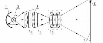
Circuit of a simple oscilloscope
To understand how the device works, study the standard block diagram.
Block diagram of an oscilloscope
Oscilloscope - concept and design of the device
Two types of beam deflection are involved in the formation of a signal on the screen: vertical and horizontal. Using the coordinate system, these developments were designated as: Y and X.
In the vertical scanning unit, the signal supplied to the channel through the attenuator is processed. It regulates the amplitude of the studied quantities step by step, preventing the proper level from being exceeded. This keeps the image within the confines of the display.
To synchronize the operation of the master oscillator node X - deviation from the vertical scan channel, a signal is supplied to it. By default, channel Y operates in open mode. The vertical deviation of the beam in this case exactly coincides with the signal level. The interference of a constant component, if present, will shift the picture or drive it beyond the boundaries of the display. This greatly interferes with operation and requires constant adjustment of the step controller.
Using closed entry mode helps avoid this. A closed video input means connecting a capacitor between it and the circuit. The capacitor acts as a capacitive filter for the DC component of the input signal.
The horizontal scan channel (X) is connected to the generator. It issues commands to deflect the CRT beam horizontally and operates in four positions:
- Internal synchronization mode. Used to process a signal having a constant frequency. It is possible to operate in self-oscillation mode, where the frequency is set manually. The frequency is captured immediately after input and the picture stability is increased.
- External synchronization mode, when the generator is started from an incoming pulse. Relevant when synchronization is carried out from input Y, through which the signal under test is supplied. The trigger command is executed on the rise or fall of a surge, as well as on a command from an external ripple source. This operating procedure is convenient for considering unstable oscillations.
- Ensuring synchronization from a power supply of 220 V, 50 Hz. Used in determining distortion and interference from power supplies. The unit starts up simultaneously with network voltage pulses.
- A single manual start is applicable for monitoring signals from logic circuits of a non-periodic nature. To turn the generator back on, it is “cocked” again.
For your information. The final formation of the signal levels of the two sweeps is performed by the final amplifiers.
Program “Computer – oscilloscope”
DIY oscilloscope
Digital Oscilloscope V3.0 is a popular amateur radio program that will turn your computer into a virtual oscilloscope
Good afternoon, dear radio amateurs! Welcome to the “Amateur Radio” website
Today on the site we will look at a simple amateur radio program that turns a home computer into an oscilloscope.
There are two ways to turn a personal computer into an oscilloscope. You can buy or make a set-top box that connects to your PC. The set-top box will be an ADC, software-controlled. And install the appropriate program on your PC. But this is a costly method. The second method is cost-free; any PC already has an ADC and a DAC - a sound card. Using it, you can convert your computer into a simple low-frequency oscilloscope, just by installing software, and you will have to solder a simple input divider. There are quite a few such programs. Today we will look at one of them – Digital Oscilloscope V3.0.
Digital Oscilloscope V3.0 (149.8 KiB, 61,161 hits)
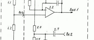
After starting the program, a window will appear on the screen that looks very similar to a regular oscilloscope. The linear input of the sound card is used to supply the signal. You usually need to apply a signal of no more than 0.5-1 volt to the input, otherwise a limitation occurs, so you need to solder the input divider according to a simple circuit, as shown in Figure No. 2.
KD522 diodes are needed to protect the sound card input from too much signal. After connecting the circuit and input signal, you need to turn on the oscilloscope. To do this, click the RUN field with the mouse and select START or click the triangle in the second row from the top of the window. The oscilloscope will show the signal. The frequency and period of the signal will be displayed in the lower right corner of the screen. But the voltage shown by the oscilloscope may not correspond to reality. When setting up an input divider, you need to try to set the division coefficient with a variable resistor so that the voltage shown on the screen is as realistic as possible.
Purpose of governing bodies. TIME/DIV – time/division; TRIGGER – synchronization; CALIB – level; VOLT/DIV – voltage/division. And one more advantage of this program is that the oscilloscope has a memory - you can stop the work, and an oscillogram will remain on the screen, which can be saved in the PC memory or printed.
Single channel model
Oscilloscope s1 73
Such a device has one input - one beam. The structural structure is shown in Fig. higher. The scheme includes:
- screen – CRT;
- Y-scan block: attenuator, pre-amplifier, delay circuit, initial sync gain and final output amplifier;
- X-scan unit: synchronization device, scan unit, output amplifier;
- backlight amplification circuit;
- calibrator;
- network power supply.
In such a device, the monitoring signal is supplied to one input and is displayed by the movement of the beam on the screen. This is enough to measure a number of parameters.
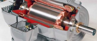
Power supply
This oscilloscope uses a 7L055I ray tube, which differs from many others in that it requires a voltage of about +1000V to be applied to its “bulb” (to the anode). If you use another beam tube in this device, for example, 5L038I, then a +1000V source is not needed.
Rice. 2. Power supply circuit for an oscilloscope.
The oscilloscope's power supply is somewhat unusual. The fact is that in order not to manufacture a transformer with a high-voltage secondary winding, two more affordable ready-made transformers with low-voltage windings were used, connected, as it were, counter-currently. Transformer T2 operates as a step-down transformer, and transformer T1 operates as a step-up transformer.
The +1000V voltage is obtained by a simple diode multiplier.
It should, however, be noted that such a power source also has a drawback - the real alternating filament voltage is, in fact, 5.9V. In principle, for 7L055I this is enough, but if another beam tube does not work well, you need to take measures to increase this voltage, for example, by bridge rectification or use another transformer T2, which has secondary windings of 6.3...7V.
Dual Channel Devices
DIY Mimo 4g lte antenna
When it is necessary to compare two types of signals, such devices are used. There are two varieties:
- Two-channel – for observing pulses from identical Y-channels. By switching the toggle switch, output signals are alternately supplied to the CRT plates. Observe each signal of inputs Y1-Y2 separately or together. The second - at each reverse sweep.
- Double-beam - they have two separate Y-channels and a two-beam CRT design. Such a device has a joint start of the horizontal scan generator, the inclusion of vertical scan occurs for each channel separately. This allows you to see 2 waveforms simultaneously.
Assembling a 5 V device
A full-fledged digital device in this line without its own display is called a USB oscilloscope. Kits of component materials are sold for learning how to work with such devices. The kit includes:
- device;
- USB power cable;
- 2 probes with “crocodiles”;
- software product on disk.
Connects to PC via USB cable. The meter assembled from the kit is suitable for acquiring initial skills. In homemade circuits, such a prefix is assembled on an MMP20 microcircuit.
Computer as an oscilloscope, spectrum analyzer, frequency meter and generator
Modern measuring equipment has long merged with digital and processor means of control and information processing. Arrow indicators are already becoming nonsense even in cheap household appliances. Analytical equipment is increasingly being connected to conventional PCs via special adapter cards. Thus, the interfaces and capabilities of application programs are used, which can be upgraded and expanded without replacing the main measuring units, plus the computing power of a desktop computer.
In addition, expanding the capabilities of a conventional computer is possible through a variety of software and hardware - special expansion cards containing measuring ADCs (analog-to-digital converter) and DAC (digital-to-analog converter). And the computer very easily turns into an analytical instrument, for example, a spectrum analyzer, oscilloscope, frequency meter..., as well as many other things. Similar tools for upgrading computers are produced by many companies. However, price and narrow specificity do not make this equipment widespread in our conditions.
But why go far? It turns out that a simple PC in its design already contains tools that, with some limitations, can turn it into the same oscilloscope, spectrum analyzer, frequency meter or pulse generator. Agree, it’s already a lot. In addition, all these transformations are done only with the help of special programs, which are also completely free and anyone can download them on the Internet.
You are probably asking a logical question: how can you do without ADCs and DACs in measurements? No way. But both are present in almost every computer, although they are called differently - a sound card. Why not an ADC/DAC, please tell me? This has long been understood by those who wrote a lot of programs for it that have nothing to do with playing music. After all, a regular PC sound card is capable of perceiving and converting a signal of complex shape within the audio frequency and amplitude up to 2V into digital form from the LINE-IN input or from a microphone. The reverse conversion is also possible - to the LINE-OUT (Speakers) output. Thus, you can work with any signal up to 20 kHz, or even higher, depending on the sound card. The maximum input voltage level limit of 0.5-2 V is also not a problem - a primitive voltage divider using resistors is assembled and calibrated in 15 minutes. It is on these simple principles that software is built: oscilloscopes, oscilloscopes, spectrum analyzers, frequency meters and, finally, pulse generators of various shapes. Such programs emulate on the computer screen the operation of devices familiar to us, naturally with their own specifics and within the frequency range of your sound card.
How it works? For the user everything looks very simple. We launch the program; in most cases, such software does not even need to be installed. An image of an oscilloscope appears on the monitor screen: with a screen with a coordinate grid characteristic of these devices, there is also a control panel with buttons, sliders and controls, which also often copy the appearance and shape of those from real hardware oscilloscopes. In addition, software oscilloscopes may have additional features, such as the ability to save the spectrum under study in memory, smooth and automatic scaling of the signal image, etc. But, of course, there are also disadvantages.
How to connect to a sound card? There is nothing complicated here - to the LINE-IN socket, using the appropriate plug. A typical sound card has only three sockets on the socket: LINE-IN, MIC, LINE-OUT (Speakers), respectively, line input, microphone, output for speakers or headphones. The design of all sockets is the same, and accordingly the plugs for all are the same. The oscilloscope program will work and display the spectrum even if an audio signal is recorded using a microphone connected to its input. Moreover, most software oscilloscopes, spectrum analyzers and frequency counters function normally if at the same time some other signal is output to the LINE-OUT output of the sound card using another program, even music. Thus, on the same computer you can set a signal, say, using a generator program, and immediately monitor it with an oscilloscope or spectrum analyzer.
When connecting a signal to a sound card, some precautions should be taken to prevent the amplitude from exceeding 2 V, which can lead to consequences such as failure of the device. Although for correct measurements the signal level should be much lower than the maximum permissible value, which is also determined by the type of sound card. For example, when using a popular inexpensive board on the Yamaha 724 chip, a signal with an amplitude of no higher than 0.5 V is normally perceived; if this value is exceeded, the signal peaks on a PC oscilloscope appear cut off (Fig. 1). Therefore, to match the supplied signal with the input of the sound card, you will need to assemble a simple voltage divider (Fig. 2).
10V Oscilloscopes
In circuits with similar voltages, closed-type resistors and a zener diode are used. Their vertical sensitivity parameters are selected up to 2 mV. When calculating the bandwidth, the maximum resistance of the device is consistent with the capacitance of the wire capacitors. Diodes are selected with a voltage of 2 V, it is advisable to select field resistors. Choosing diodes for this voltage will reduce the sampling frequency to a minimum and increase the transmission speed. Due to the rapid sweep of data, the limiting frequency drops sharply. Using a zener diode or a divider made from a modulator will help solve this problem.
10V circuit
Converting a Computer to an Oscilloscope
After clarifying the initial computer data and personal needs, they begin to select an electrical circuit.
To get acquainted with professional solutions, you can study the designs of serial measuring instruments
Set-top box diagram
For high-quality reproduction without extensive practical experience, it is better to choose relatively simple designs. However, the electrical circuit presented below is quite capable of ensuring minimal signal distortion while simultaneously performing protective functions.
This adapter circuit can be created quickly without unnecessary difficulties
Description:
- the set-top box resistors are evaluated in conjunction with the Rin of the computer in order to correctly calculate the divider parameters;
- capacitors equalize the frequency response;
- Zener diodes installed in the manner shown in the figure prevent damage to the computer’s audio input when a high-amplitude signal is supplied (switch position “1:1”);
- additional current protection is provided by R1.
You can hardly count on complete passport data, especially if you have old computer equipment. Most likely, you will have to measure the impedance at the sound card input. To do this, a reference signal (50 Hz, sinusoid) is created at the output of the same block using a special “Virtual Generator” program. The following calculation is performed using the formula:
Rx=R1*(U1/(U2-U1)).
Example:
60*(120/(520-120))= 18 kOhm.
Knowing the input resistance, create a voltage divider using one of the presented circuits
Set-top box collection
To eliminate the parasitic influence of external electromagnetic radiation, the set-top box is placed in a metal case. It can be created from a suitable duralumin sheet with a thickness of 1.5-2 mm. A CP-50 type connector is attached to the input so that standard probes can be connected without problems. The output is a flexible cable with a Jack plug that matches the input jack of the computer audio card. For assembling a simple electrical circuit, surface-mounting technology is quite suitable.
How to make a 15 V model
During assembly, linear resistors are used, the resistance of which is at the limit level - 5 MΩ. This allows the zener diode to operate in a gentle mode. When selecting capacitors, the threshold voltage is first measured by the tester.
Attention! The test results obtained, when using tuning resistors for the device, can be inaccurate. Linear resistors should be used.
When assembling, do not forget to mount a port connected through a probe to the microcircuit, while a divider is connected through the bus. The use of vacuum diodes in the assembly will allow you to control the level of oscillation amplitude.
15V Oscilloscope
Using PPR1 series resistors
Devices containing elements of this line are very popular. Due to their high sensitivity, they are used for monitoring electrical equipment. To create this meter you will need a CRT, a pulse modulator, a rectifier and contactors with plates. The installation of a kenotron is justified by the accuracy of the readings obtained. The operational type device requires the installation of a controller.
The resistance value is not higher than 34 Ohms, and the signal conductivity is 4.2-4.5 Ohms. A USB port is connected through a low conductivity modulator. Spectral expanders for the circuit are taken of the pulse type.
Important! It is necessary to organize voltage stabilization, fix the expander next to the comparator, which will reduce heat losses.
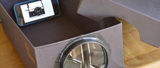
Assembling a pocket oscilloscope based on Android
If the frequency to be measured is in the range of 20 kHz (sound audible to the ear), then use headphones with a microphone. To assemble a new device based on the Android OS, you can do without additional components. A 3.5 mm jack is taken from the headset. Probes are soldered to the microphone contacts. A measurement limit switch is inserted between them and the plug. Download the Oscilloscope application to your phone. The signal received at the microphone input will be displayed on the screen.
Measurement limits switch circuit
Pros and cons of the “android” build
There are more disadvantages to this method than advantages. Minuses:
- does not provide measurement accuracy;
- allows only high-frequency signals to be measured;
- it is impossible to measure transient processes at constant voltage;
- the gadget's input is at risk.
There are few advantages:
- 20 minutes of installation time;
- assembly is easy.
It's hard to call this attachment a good measuring device.
What is needed to create an oscilloscope
If you need a more accurate oscilloscope from a PC, you will have to make a special USB attachment. This is a slightly more difficult task - it is advisable for the user to have such basic amateur radio skills as constructing circuits, soldering, and also know where to purchase the necessary materials.
- MCP1700;
- STM32F042Fx;
- MCP6S21.
If the purpose of working with the device is not something serious, a simpler and faster option would be a simple oscilloscope from a sound card, which does not require additional manipulations with the circuits.
Programs
Without special software, nothing will work - fortunately, anyone can find everything they need on the Internet and download it. It is necessary to start programs after setting up the equipment.
It will not be difficult to understand how the programs work - most of them are adapted for a Russian-speaking audience and support a Russian interface.
The best oscilloscope programs:
- Winscope. One of the most popular programs, can be used to analyze any type of signals. It can also save data in a user-friendly format, measure frequencies, build charts and perform other analytical actions.
- Visual Analyzer. The program is for Windows 10. A special feature is the presentation of received and processed information on two screens. The first one shows standard data, and the second one shows the FFT of the signal. The user can also customize program filters for any of their purposes.
- Soundcard Oscilloscope. For personal use, this program can be used for free. The advantages of the software are its versatility, the ability to send a signal to the device’s speakers, as well as the generation of custom signal and noise channels.
- Oscilloscope. A program designed not for analysis, but for viewing - with its help you can only visualize the XY spectra of a signal or audio file on the screen. Mainly used as entertainment software.
- Frequency Analyzer. Can work through a microphone, shows real-time signal analysis. Highly configurable - user can select FFT, sampling rates and conversion points, as well as between 8 and 16 bits.
- Real-time Spectrum. Reads signal spectra (reception via 3.5 mm audio jack) and displays them on the screen. The user can view the signal from any channel (or both), adjust the dynamic range of the graphic display, as well as the frame rate.
- AUDio MEasurement System. Works using a microphone. Functionality includes a signal generator, frequency response measurement, and spectrum analysis. A simple program, without special functions, ideal for simple signal analysis.
All these programs can be found in the public domain - a search or any computer forum will help you with this. Depending on what you need to configure your oscilloscope online for, choose simple or complex programs.
Equipment
As stated earlier, most of the hardware you need is already inside your PC. To analyze simple signals, it is enough to use a microphone (the sound will come through the speaker), an audio connector or a USB port. If the purpose of your work with a homemade oscilloscope is simple curiosity, then you may not need the computer itself; you can make an oscilloscope from a tablet.
Sound card
A sound card is necessarily present in all personal computers and even in mobile devices. The output to it (port) is usually a 3.5 audio jack. mm. It is very simple to use, just connect to it a signal supply device or a device that receives a signal (for example, a microphone).
Monitor
Every PC has a monitor, as well as a sound card. For a desktop computer this is a separate monitor, for a laptop it is a built-in monitor. Any monitor, even an outdated one, is sufficient to analyze an audio signal.
Frequency meter
Like the previous device, it is easy and cheap to purchase. The user rarely needs a real frequency meter, since there have long been virtual analogues that work just as well, but at the same time do not require any special skills.
Assembling an oscilloscope from a tablet
It is possible to mount an oscilloscope from a laptop or tablet using the Hantek-6022BE-2-20-USB-PC attachment. The tablet is used as a monitor. Control of measurements by command - from the screen or with the mouse.
Hantek console
Software for oscilloscope on tablet and android
If you make a USB oscilloscope from a sound card yourself, download the software. The program is downloaded from the Play Market or other similar sites for downloading applications. Such programs allow you not only to achieve accurate measurements for the tablet, but also to perform the necessary signal calibration.
Wideband frequency using a separate gadget
The use of a separate device will allow you to expand the frequency range. It includes an analog to digital converter. Further pulses are sent in digital format. Measurement accuracy increases. Available as a portable device with a display.
Probe for computer oscilloscope
Even if you have a lot of different industrial cables, it wouldn’t hurt to make your own probe cable for an oscilloscope that operates at low frequencies.
The advantage of this type of homemade cable is its flexibility and small size, which is very convenient.
The downside is that the scope of its operation is limited to the repair of primitive audio equipment. To use a homemade oscilloscope, a “probe cable” will be quite sufficient.
Oscilloscope from an Android tablet
When purchasing an oscilloscope attachment, the OS selected is not “Windows”, but “Android”. The set-top box must support the following options:
- Bluetooth channel;
- data transfer using Wi-Fi.
This will allow you to do without contact connection between the gadget and the set-top box.
Bluetooth channel
Connecting via Bluetooth has limitations:
- the tested frequency has a limit of 1 MHz;
- U probe = 10 V;
- coverage area – 10 m.
This limits the resource when using these types of connections.
Transfer data using Wi-Fi
It is possible to connect an oscilloscope from a Linux tablet or another manufacturer via a wireless network - a wi-fi channel. The package of measurements is issued on the tablet without delay and for an unlimited number of project participants. The presence of a recording option allows you to work with information in offline and online versions. The connection range is higher than Bluetooth.
DIY USB oscilloscope circuit diagram
Using a 5 V source and connecting via a USB cable, you can assemble such a circuit yourself.
USB oscilloscope circuits
The creation of such devices independently is justified for measurements that do not require accurate results. An approach to solving the issue is to use a ready-made, full-fledged console.
Electrical diagram
If you still decide to work through a homemade console, then you will need a circuit for a do-it-yourself oscilloscope from a computer. This scheme is quite simple and working on it will not be difficult for anyone who has done something similar at least once. You will need tools and skills for basic work with circuits - connections, theoretical knowledge.
IMPORTANT! There are more complex schemes, but it is better for a beginner to start with the elementary version. If the first attempt is suitable for solving the problem, then for subsequent attempts the complexity can be increased by soldering a new, more advanced circuit.