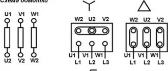
The asynchronous electric motor is powered from a three-phase AC network. Such a motor, with a simple connection diagram, is equipped with three windings located on the stator. Each winding is shifted relative to each other by an angle of 120 degrees. A shift at such an angle is intended to create rotation of the magnetic field.
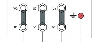
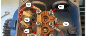
The ends of the phase windings of the electric motor are brought out to a special “block”. This was done for ease of connection. In electrical engineering, two main methods are used for connecting asynchronous electric motors: the “delta” connection method and the “star” method. When connecting the ends, jumpers specially designed for this purpose are used.
Differences between "star" and "triangle"
Based on the theory and practical knowledge of the basics of electrical engineering, the “star” connection method allows the electric motor to operate smoother and softer. But at the same time, this method does not allow the engine to reach the full power presented in the technical specifications.
By connecting the phase windings in a delta pattern, the motor is able to quickly reach maximum operating power. This allows you to use the full efficiency of the electric motor, according to the technical data sheet. But this connection scheme has its own drawback: large inrush currents. To reduce the value of currents, a starting rheostat is used, allowing for a smoother start of the engine.
Star connection and its advantages
Reversible motor circuit 380 to 220 Volts
Each of the three working windings of the electric motor has two terminals - the beginning and the end, respectively. The ends of all three windings are connected to one common point, the so-called neutral.
If there is a neutral wire in the circuit, the circuit is called 4-wire, otherwise, it will be considered 3-wire.
The beginning of the terminals is connected to the corresponding phases of the supply network. The applied voltage on such phases is 380 V, less often 660 V.
The main advantages of using the star scheme:
- Stable and long-term non-stop operation of the engine;
- Increased reliability and durability by reducing equipment power;
- Maximum smooth start-up of the electric drive;
- Possibility of exposure to short-term overload;
- During operation, the equipment housing does not overheat.
There is equipment with internal connection of the ends of the windings. Only three pins will be output to the block of such equipment, which does not allow the use of other connection methods. Electrical equipment made in this form does not require competent specialists for its connection.
Connecting a three-phase motor to a single-phase network using a star circuit
Connection options
Three-phase motors have excellent characteristics, a fairly wide range of models and are used in a wide variety of devices. Therefore, they are used both in industrial devices with three-phase power supply, and in household single-phase electrical installations. Next, we will analyze both options for connecting electrical machines.
To a single-phase network
The design feature of a three-phase unit, in contrast to single-phase asynchronous motors, is the need for a phase shift in the windings, otherwise the shaft will not rotate. To change the situation, one phase is divided for all three windings, two of which include additional inductance and starting capacitance. Which provide a shift in current and voltage relative to the voltage in the network. Inductance allows you to shift the voltage to the negative region up to -90°, but a single-phase capacitor, on the contrary, to the positive region up to +90°.
Graphically, the voltage-current lag function will look like this:
Change in current and voltage across capacitance and inductance
However, in practice, the bias is provided only by capacitive elements, which are included in the power supply circuit of one of the windings, and the other two are run between the phase and neutral wires. The connection diagram for a three-phase motor in a single-phase circuit is shown in the figure below:
Connection diagram to a single-phase network
As you can see in the figure, a tap is made from the phase wire containing a single-phase capacitor magazine of two elements, one for starting C2, the second for constant operation of C1. When the start button is pressed, contacts SA1 and SA2 close simultaneously, but after sufficient torque has been created and rotation has begun, SA1 is discarded and removes C1 from the circuit, leaving C2. Power, with this engine switching scheme, is reduced to 30 - 50%.
Capacitor starting is calculated using the formula:
Serb = (2800*I)/U - to turn on a three-phase motor with a star
Crab = (4800*I)/U - to turn on a three-phase motor with a triangle
The starting capacitor is used only in loaded starting, so it can not be used in light starting. Then, instead of the launcher capacity, the worker will be used.
To a three-phase network
In a three-phase network, despite the presence of the required type of supply voltage, a magnetic starter is always used to drive the motor into rotation. Starting without a starter or contactor is quite dangerous, so they are an integral element.
Connection diagram to a three-phase network
The figure above shows a typical diagram for connecting a motor to a three-phase network, which works on the following principle:
- Voltage is supplied to the engine from the mains through switch 1.
- further, when the start button 6 is turned on, the contactor coil 4 is powered, which attracts the power contacts of the starter 3;
- after which the engine begins to rotate, and the start button 6 is bridged through the repeater 5;
- to stop the three-phase motor, use the Stop button - 7, which is in the normally closed position;
- Motor overload protection monitors the current load in the network and, if a threat arises, opens contacts 2.
This diagram can be simplified due to the design features of the starters used. Since some of them are manufactured without repeaters, they may have the function of reversing a three-phase motor or be produced without protection. You can get more detailed information about magnetic starters from the corresponding article on the website:
Triangle connection and its advantages
The principle of the “triangle” connection is to connect in series the end of the winding of phase A with the beginning of the winding of phase B. And then, by analogy, the end of one winding with the beginning of another. As a result, the end of the phase C winding closes the electrical circuit, creating an unbroken circuit. This scheme could be called a circle, if not for the mounting structure. The triangle shape is given by the ergonomic placement of the winding connection.
When connected by a “triangle” on each of the windings, there is a linear voltage equal to 220V or 380V.
The main advantages of using the triangle scheme:
- Increasing the power of electrical equipment to the maximum value;
- Using a starting rheostat;
- Increased torque;
- Large traction forces.
Flaws:
- Increased starting current;
- When running for a long time, the engine gets very hot.
The “triangle” method of connecting motor windings is widely used when working with powerful mechanisms and the presence of high starting loads. A large torque is created due to an increase in the self-induction EMF caused by large flowing currents.
Connecting a three-phase motor to a single-phase network using a triangle diagram
Star-delta connection type
In complex mechanisms, a combined star-delta circuit is often used. With this switching, power increases sharply, and if the engine, according to its technical characteristics, is not designed to operate using the “delta” method, it will overheat and burn out.
Motors with increased power have high starting currents, and as a result, when starting, they often cause fuses to blow and circuit breakers to turn off. To reduce the line voltage in the stator windings, autotransformers, universal chokes, starting rheostats or a star connection are used.
Star and delta connection diagrams
In this case, the voltage at the connection of each winding will be 1.73 times less, therefore, the current flowing during this period will be less. Then the frequency increases and the current reading continues to decrease. Then, using a relay contact circuit, a switch from “star” to “triangle” will occur.
As a result, using this combination, we will obtain maximum reliability and effective productivity of the electrical equipment used, without fear of damaging it.
Star-delta switching is permissible for electric motors with a light starting mode. This method is not applicable if it is necessary to reduce the starting current and at the same time not reduce the high starting torque. In this case, a wound-rotor motor with a starting rheostat is used.
Main advantages of the combination:
- Increased service life. Smooth start allows you to avoid uneven load on the mechanical part of the installation;
- Possibility of creating two power levels.
Start relays
In order to start the electric motor according to the star-delta circuit, special equipment has been developed. The names may be different: “Start-delta” relays, “Start time relays”, etc., but the scheme of their operation is always the same: after voltage is applied to the relay, the acceleration time starts counting, the star starter is turned on, then, at the end During acceleration, the contacts open, the starter turns off, and the contacts that turn on the delta starter close.
Similar relays are produced in the Czech Republic (CRM-2T, TRS2D), Austria (RVP-3, D6DS, VL-32M1), Ukraine (VL-163), Italy (80 series, Finder). They can be modular, programmable, removable, single- or multi-functional, mechanical or digital, daily, weekly - the choice is quite wide.
So, the question: how to connect an electric motor with a star or a triangle is solved quite simply. Carefully read the instructions supplied with the unit, paying special attention to the marks on the motor tag.
Blitz tips
- At the moment of starting the electric motor , its starting current is 7 times greater than the operating current.
- The power is 1.5 times greater when connecting the windings using the delta method.
- To create a smooth start and protect against motor overloads , frequency wires are often used.
- When using the star connection method , special attention is paid to the absence of “phase imbalance”, otherwise the equipment may fail.
- Linear and phase voltages in a delta connection are equal to each other, as are line and phase currents in a star connection.
- To connect the motor to a household network, a phase-shifting capacitor is often used.
Connecting the electric motor windings in a star configuration
When connecting the phases of an electric motor with a star, the three windings are connected to each other at a common point. The free ends are each connected to their own phase of the network. In some cases, the common point is connected to the neutral bus of the power supply system.
The figure shows that for this connection, the phase voltage of the network is applied to each winding (for 0.4 kV networks - 220 volts).