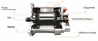
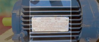
An asynchronous motor is a rather complex system, which is characterized by many parameters, including versatility. Units drive different equipment components and can be started using a variety of methods. We will consider the most popular of them today.
Capacitor for an asynchronous motor
An electric motor, like any complex electrical system, is regulated by certain requirements and standards, with the help of which safety and performance are achieved. Such parameters concern many aspects of the motor, including its start. The first thing that must be observed is the absence of additional tools; the start must be carried out using available means. The second is to minimize starting currents and the starting torque itself. Further in the article we will briefly describe the main methods, the implementation of which fully meets the requirements described above.
Start directly
This common method is based on connecting the stator windings to the electrical power supply network without “intermediary” elements. Most often, such a start occurs in motors with squirrel-cage rotors. Such power units have low power; when their stator windings are directly connected to the power supply network, overheating does not occur due to inrush currents. Thanks to this, the equipment does not fail.
The ratio of the inductance of the coils in asynchronous electric motors to the resistance level is quite small. This number becomes even lower when the device has a lower power rating. This causes a rapid attenuation of the free current that is generated during the startup process. This feature makes it possible to neglect such current without including it in the calculation. It is worth taking into account only the force that was established during the implementation of the transition process.
Direct starting of an asynchronous motor
As you can see in the image of the magnetic starter, the component performs automatic acceleration using a natural mechanical characteristic (M in the diagram). This is realized from point P (the immediate start of the launch) until the moment at which M reaches a level equal to the resistance indicator (Ms). The magnetic starter itself is structurally an electromagnetic type switch installed on power units with squirrel-cage rotors.
In the second part of the picture you can see a graph of the starting current versus the first moment. Knowing this, we can say that the acceleration for acceleration is equal to the difference in the abscissa of two graphs: M and Ms. Based on this, if the starting M is less than Ms, then sufficient overclocking will not work. In order to implement it, you need to have an optimal value for Mput. In the case of a power unit with a squirrel-cage rotor, it is best to use special formulas, here is one of them:
Formula
At the same time, it is worth considering that the slip coefficient s in the formula is stable and equal to unity.
The ratio of M starting and M nominal is a value that is determined by the multiple of the starting torque. For convenience, this resulting number is indicated as Kpm. In the case of electric motors equipped with squirrel-cage rotors, this coefficient reaches 1.8 and is regulated by state standards.
For example, in situations where Kpm is 1.5 and nominal M is 5000 Nm, direct start starts from Mpm - 7000 Nm.
It is also worth noting that there is no need to exceed the indicators specified by GOST, because this is fraught with a sharp increase in active resistance on the rotating components of the electric motor.
The advantages of the direct motor starting circuit diagram include:
- low cost of implementation;
- simplicity of design;
- minimum heating of the windings during the startup process.
Let us also note the disadvantages of such a movement:
- M starting is 3 times higher than M nominal;
- the starting current reaches 800% of the nominal level.
But, despite the weaknesses of this motor starting and braking scheme, it remains one of the most preferred for implementation in asynchronous electric motors. It is especially advantageous to implement a direct start with squirrel-cage rotors, because it provides the power unit with high energy characteristics. Also, this scheme uses one button or several at once, responsible for “start” and “stop”.
Starting with a frequency converter
A frequency converter is an electronic static device designed to control an asynchronous or synchronous AC motor. An electrical voltage with variable amplitude and frequency is generated at the output of the converter. The name “frequency converter” is due to the fact that the motor rotation speed is controlled by changing the frequency of the supply voltage supplied to the motor from the converter. The inverter converts the supply voltage of 220V/380V with a frequency of 50Hz into an output pulse voltage, which generates a sinusoidal current in the motor windings with a frequency of 0 to 400 Hz and higher. A frequency converter makes it possible to adjust the speed of an AC motor, changing the characteristics of the electrical network. Depending on the settings of the frequency converter, when low voltage is applied, the pump may run at low speed. When the demand for water intake is small, operating the pump at reduced power saves energy and increases engine life. But, most importantly, at the moment the pump starts, the engine begins to operate at the lowest frequency, gradually accelerating to the specified speed, which eliminates water hammer. A variable-frequency electric drive, in general terms, consists of a three-phase AC electric motor and an inverter, which provides, at a minimum, smooth starting of the electric motor, stopping it, changing the speed and direction of rotation. The possibility of such regulation improves the dynamics of the electric motor and, thereby, increases the reliability and durability of the process equipment. Moreover, the inverter allows you to implement automation of almost any technological process. This creates a feedback system where the inverter automatically changes the rotation speed of the electric motor in such a way as to maintain various system parameters, for example, pressure, flow, temperature, liquid level, etc., at a given level. Due to optimal control of the electric motor depending on the load, electricity consumption in pumping, fan, compressor and other units is reduced by 40-50%, and starting currents, amounting to 600-700% of the rated current and being a scourge for starting and control equipment, disappear completely. Thus, the use of adjustable electric drives based on frequency converters makes it possible to create a new energy-saving technology, which not only saves electrical energy, but also increases the service life of electric motors and technological equipment in general.
Start by reducing voltage
This method of starting the motor smoothly is used with engines that operate at high power. The method is also suitable for units with average power, but provided that the voltage level of the operating power supply network does not allow acceleration using the direct start method described above.
In order to reduce the voltage in the unit, you can use one of three methods:
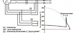
- switch the stator windings from a normal triangle type circuit to a star starting circuit. You need to start with the latter, and when the device reaches the nominal frequency, you should switch to triangle. In such a situation, the voltage that supplies the phases of the stator windings is reduced by approximately 1.73 times. This makes it possible to reduce phase currents and reduce linear currents by 3 times;
- start using additional resistance, which contributes to a general reduction in voltage on the stator winding. When a start-up is implemented, resistor components or reactors are connected to the electrical circuit, which will provide active or reactance;
- starting by connecting the motor through a transformer. In this case, several degrees are used at once, switching automatically.
The second (reactor) and third (transformer) methods are shown in the figure:
Undervoltage
The main benefit of implementing this method is the provision of the ability to accelerate the power unit at a voltage level almost equal to that required to ensure normal operation.
The weaknesses of autotransformer starting include a significant reduction in MP levels and maximum torque. These indicators directly depend on the level of supply voltage: the lower the current in volts, the smaller these moments will be. Based on this, we can say that under such conditions the unit with a load simply will not self-start.
Smooth start
The soft start method of a 12V DC electric motor is used as an alternative to the rheostatic one. It is used in situations where the task of controlling rotation speed is not necessary. An example is emergency turbine pumps.
The principle of operation is as follows: after starting the DC electric motor, a device is activated that holds the armature current within a certain value, which is higher than the current on the motor shaft, and this voltage regulator operates until the engine speed reaches rated values.
After this, the EPT begins to operate in normal mode, corresponding to the voltage of the power source, which does not necessarily have to be a low-power DC network - the use of batteries is allowed. Its connection to the motor is carried out through special contactors.
Note that with the soft start method of a DC motor, different starting schemes are used - from single-phase to three-phase. The latter is more difficult to implement, but is considered the most reliable and universal.
Regardless of the type of start (direct, smooth, rheostat) of a DC motor, several types of excitation are used:
- sequential;
- parallel;
- independent.
Let us consider the features of starting an electric motor of the listed types of excitation.
Application of a rheostat
This method involves connecting the rotor using a rheostat at the moment it is turned on. The method is implemented to start motors whose rotor is of the phase type. In situations where the design of the rotor chain already includes a rheostat, the active resistance indicator increases. At the same time, point K approaches point O and is already marked K'. This does not help reduce the maximum M, but increases the starting M. This can be clearly seen in figure “a” below.
Connecting the rotor to the rheostat circuit
In parallel with this, the critical slip increases, and the dependence of the moment on the index s
shifts to the area of stronger slips. The exact number of revolutions moves towards the sphere of weaker speeds. In the figure, these situations are demonstrated in graphs “b” and “c”, respectively.
As a rule, a rheostat, which is used to reduce the engine starting time, has from 3 to 6 stages in its design. The starting resistance gradually decreases, which is directly ensured by the larger starting M. At the very beginning, the engine is driven by the fourth parameter (below in Figure B). This number fully corresponds to the resistance of the rheostat used and demonstrates the highest starting power.
Rheostat
The torque of rotation (hereinafter Mtor) gradually decreases as the number of revolutions of the movable elements increases. When a certain minimum value is reached, the rheostat must be turned off in order for MVR to be restored to the maximum (characteristic No. 3). But, based on the fact that the number of revolutions still increases, the torque decreases. In this case, another component of the rheostat is switched off, after which the unit operates according to the second parameter. When a complete shutdown of both the rheostat and the phase rotor occurs, then we have completed the starting process. The power unit operates entirely according to the first characteristic.
Starting the motor in this way is based on changing the Mvr parameter - from the highest to the minimum values. The resistance level decreases in steps, completely corresponding to the broken curve. The exclusion of rheostat parts is carried out manually or automatically.
The advantages of this method include the possibility of use with electric motors based on wound rotors. Here the operator has the opportunity to turn on the unit at M start, which is extremely close to the M max levels. At the same time, it is worth noting that the starting currents have minimal values. Their strengths can be changed as indicated in image B.
Despite the rather impressive advantages, there are also disadvantages. These include:
- complex connection;
- the need to use more expensive motors in the system, including the wound rotor already familiar to us;
- performance characteristics are worse than those of motors with similar parameters, but with a squirrel-cage rotor.
Mainly due to their shortcomings, most phase motors are used only when difficulties arise with other types of units.
Rheostat start
This method, unlike the previous one, is used to ensure the start of high-power electric motors.
To do this, a rheostat is included in its electrical circuit, which is a sectional wire with a high resistivity. With the rheostatic method of starting an EPT, the resistance of the rheostat quickly decreases, which eliminates large current drops.
This technique allows the electric motor shaft to accelerate with constant acceleration, which has a positive effect on the durability of the engine. The number of rheostat sections can vary widely, usually 2-7 segments. Their number depends on the difference between the maximum and minimum values of the starting current, as well as on the requirements for smooth starting.
The problem of ensuring equalization of starting current values at all stages of the process within a given time period is solvable, but in general it cannot be automated. If it is impossible without this, that is, the EPT is part of an automated complex; a technique with automatic contactors is used, which operate alternately and bypass the starting resistance.
When the engine reaches operating speed, the rheostat must be disconnected from the circuit, since its characteristics allow it to operate for a short time, otherwise it will simply fail. The decrease in resistance, as well as its increase at the beginning, occurs discretely.
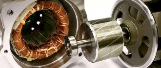
Single phase motor
The auxiliary winding is a key element in ensuring the start of an asynchronous motor on 1 phase. The created element must be located perpendicular to the working winding of the stator. But this is not enough to generate a rotating magnetic field. It is necessary that a shift in the current phase be realized, which flows through the additional winding. The offset refers to the relative current that occurs in the operating coils to provide starting.
To ensure a phase shift when the unit is connected to a single-phase network, it is necessary to include a special component in the electrical circuit. As a rule, a resistor, inductor or capacitor is used for such purposes.
After the engine acceleration reaches the required frequency values, the auxiliary winding is switched off. This is done either manually or automatically. At first, the motor operates according to two-phase characteristics, and after reaching the frequency level - according to single-phase characteristics.
Example of ohmic phase shift
Comparison of DOL and star-delta starting
The following diagrams show the currents for a Grundfos CR pump driven by a 7.5 kW Grundfos MG motor via direct-on-line (DOL) and star-delta starting respectively. As you can see, the DOL starting method is characterized by a high inrush current, which levels off and becomes constant over time. The star-delta starting method has a lower starting current, however, during the starting process, peaks are observed during the transition from star to delta.
When starting according to the “star” circuit (t = 0.3 s), the current decreases. However, during the transition from star to delta (at point t = 1.7 s), the current pulse reaches the same level as the inrush current during direct starting. The current surge may become even larger since no power is supplied to the motor during the switching period. This means that the motor loses speed before applying full voltage (phase voltage).
Starting resistance
Among the effective methods that exist in modern electrical engineering, it is worth highlighting the use of resistance at start. This technology is relevant for motors receiving power from single-phase networks. It is also important that the motor has a primary auxiliary winding with a squirrel-cage rotor. Often such a unit is called split-phase, the electrical circuit of which has a high active resistance.
In order to start such a device, it is necessary to have a starting resistor, which is connected in series to the auxiliary winding. In this case, there will be a phase shift that will reach an angle of 30 degrees. This indicator is easily enough for overclocking.
In this circuit, you can use additional winding with a high level of resistance and low inductance. Here there is a copper component with a small number of turns, and the wires have a smaller cross-section, which is a key difference from the working windings.
Other launch methods
It is also worth listing other quite popular schemes:
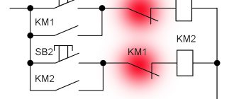
- regulation of a reversible motor with two starters (or one reversible) and three buttons;
- for a reversible motor using 2 starters and 3 keys, of which 2 have paired contacts.
All control options are, one way or another, similar to each other, but despite this, each of them is unique in its own way. It is worth choosing the exact option, focusing on the performance of the motor that will be driven.