Reversing an asynchronous motor
It so happened that three-phase asynchronous electric motors, as well as their reverse, became the most common electrical machine.
Depending on the mechanism that is driven by this electric motor, it may be necessary to change the direction of rotation of the mechanisms, and, consequently, the motor shaft, in our case a three-phase asynchronous electric motor.
Everyone probably knows this scheme:
Theoretically, to change the direction of rotation of the shaft (reverse) of an electric motor, you only need to swap two phases. It is worth noting that it does not matter which phases we change, but for the future it is customary to change the two extreme phases, that is, phase “ A ” with phase “ B ”.
To perform such manipulations with the electric motor, the above diagram must be modified - remade, modified. To do this, you will need another magnetic starter, or a contactor (depending on the power), as well as a push-button station consisting of three buttons, or three push-button contacts, two normally open (normally open), and one normally open.
This diagram will look like this. Reverse.
For clarity, each phase is highlighted in its own color: yellow phase “A”, green phase “B” and red phase “C”, the control circuit is highlighted in blue. Also, lines painted black are not live.
As you have already noticed, this reverse circuit does not differ significantly from a simple starting circuit for an asynchronous motor. All changes come down to the magnetic starter KM2 , the normally open contact of the SB 2 . It is worth noting the presence of electrical interlocking, which is expressed by block contacts of magnetic starters included in the control circuit.
Like the elementary starting circuit of an asynchronous motor, the circuit of the same motor consists of the following elements (devices):
- Input circuit breaker AB1 - three-phase voltage of the power circuit and control circuit is supplied through it;
- Two magnetic starters KM1 and KM2 , through the power contacts of which, power is supplied to the stator. Their block contacts are included in the control circuit to perform pickup and electrical blocking. The coils of these starters are also included in the control circuit. It must be said that each of the magnetic starters is responsible for a certain rotation of the rotor. For example, if power is supplied through the magnetic starter KM1 , then the electric motor shaft rotates clockwise (forward), but if power is supplied through the power contacts of the magnetic starter KM2 , then the asynchronous motor shaft rotates counterclockwise (backward).
This circuit uses magnetic starter coils designed for a linear voltage of 380V. If the coils of the magnetic starters were designed for a phase voltage of 220V, then the circuit looked like this:
reverse dvigatela katuschka 220 volt
- Thermal relay KK - bimetallic plates, which are connected in series to the stator circuit, and the contact block is in the control circuit. Serves to protect against overload.
- Two-pole circuit breaker AB2 - supplies power to the control circuit. Also, together with or without the machine, a tag key can be installed.
- Normally open contacts SB 1 and SB 2 are start buttons, each of which corresponds to the direction of rotation of the motor shaft (forward and reverse).
- Normally closed contact SB 3 – stop button.
- Well, the three-phase asynchronous motor itself D ;
Circuit operation
In order to make the circuit ready for start-up, it is necessary to turn on the input circuit breaker AB1 and the circuit breaker in the control circuit AB2.
In this state, the reverse circuit of the asynchronous motor is ready for start-up. In this case, the voltage in the power circuit is supplied through the input circuit breaker AB1 to the upper jaws of the magnetic starters KM1 and KM2 , and in the control circuit, through the circuit breaker AB2 SB3 button, voltage is supplied to the normally open contacts of the SB1 and SB2 , as well as to normally open block contacts of magnetic starters KM1 and KM2.
To start, you need to press one of the start buttons SB1 or SB2 (for example, the SB1 button was pressed).
After closing the contact of the SB1 button, the voltage through the closed block contact of the magnetic starter KM2, through the coil of the magnetic starter KM1, through the block contact KK, through the circuit breakers AB2 and AB1 will reach phase “C”. A closed circuit is formed through which alternating current begins to flow. Passing through the coil of the magnetic starter KM1, it forms a magnetic field that will draw in the armature of the magnetic starter KM1, while its power contacts will close, as a result of which the asynchronous electric motor will receive power, current will begin to flow through its windings, and it will start, the rotor will rotate. When the magnetic starter is triggered, its open contact in the control circuit will close, it will bypass the SB1 button, that is, the current will flow parallel to the start button, so that when the start button is released, the machine will not stop. Also, in the circuit of the start button SB2 , the block contact of the magnetic starter KM1 will open, this will eliminate the possibility of the second magnetic starter KM2 triggering, which will cause an interphase short circuit. All of the above happened when the “Start” button was pressed and contact SB1 was closed.
To stop the engine, you must press the “Stop” button, that is, open the contact of the SB3 button.
As a result, the circuit in which the coils are connected is open, and electric current does not flow through them. The magnetic starter will open its power contacts, causing the motor to lose power and stop. In this case, the normally open block contact KM1 (pickup) will open, this will lead to the fact that when the SB3 button is returned, the engine will not start again. Also, the normally closed contact block of the electrical locking KM1 in the coil circuit of the magnetic starter KM2 will close, providing the ability to enable reverse. The circuit will return to a state of readiness for the next engine start.
Reversible motor connection diagram
- Variable network: motor 380 to network 380
- Variable network: electric motor 220 to network 220
- Variable network: 380V to 220V
- Constant electric current: features
The direction of rotation of the motor shaft sometimes needs to be changed. This requires a reverse connection diagram. Its type depends on what kind of motor you have: direct or alternating current, 220V or 380V. And the reverse of a three-phase motor connected to a single-phase network is arranged in a completely different way.
The three most popular induction motor control schemes
All electrical circuit diagrams of machines, installations and machines contain a certain set of standard blocks and assemblies that are combined with each other in a certain way. In relay contactor circuits, the main elements of motor control are electromagnetic starters and relays.
Most often, three-phase asynchronous motors with a squirrel-cage rotor are used as a drive in machines and installations. These engines are easy to design, maintain and repair. They satisfy most requirements for the electric drive of machine tools. The main disadvantages of asynchronous motors with a squirrel-cage rotor are large starting currents (5-7 times higher than the rated current) and the inability to smoothly change the motor rotation speed using simple methods.
With the advent and active introduction of frequency converters into electrical installation circuits, such motors began to actively displace other types of motors (asynchronous with a wound rotor and DC motors) from electric drives, where it was necessary to limit starting currents and smoothly regulate the rotation speed during operation.
One of the advantages of using squirrel-cage induction motors is the ease of their connection to the network. It is enough to apply three-phase voltage to the motor stator and the engine starts immediately. In the simplest version, you can use a three-phase switch or batch switch to turn it on. But these devices, despite their simplicity and reliability, are manual control devices.
In the diagrams of machine tools and installations, the operation of one or another engine in an automatic cycle must often be provided, the sequence of switching on several engines, automatic change in the direction of rotation of the engine rotor (reverse), etc. must be ensured.
It is impossible to provide all these functions with manual control devices, although in a number of old metal-cutting machines the same reverse and switching of the number of pairs of poles to change the speed of rotation of the motor rotor is very often performed using packet switches. Switches and package switches in circuits are often used as input devices that supply voltage to the machine circuit. However, motor control operations are performed by electromagnetic starters.
Switching on the engine via an electromagnetic starter provides, in addition to all the convenience of control, zero protection. What this is will be described below.
Three electrical circuits are most often used in machines, installations and machines:
control circuit for a non-reversible motor using one electromagnetic starter and two “start” and “stop” buttons,
control circuit for a reversible motor using two starters (or one reversing starter) and three buttons.
control circuit for a reversible motor using two starters (or one reversing starter) and three buttons, two of which use paired contacts.
Let's look at the operating principle of all these schemes.
1. Motor control circuit using a magnetic starter
The diagram is shown in the figure.
When you press the SB2 “Start” button, the starter coil is supplied with a voltage of 220 V, because it turns out to be connected between phase C and zero (N). The moving part of the starter is attracted to the stationary part, thereby closing its contacts. The power contacts of the starter supply voltage to the engine, and the blocking contact closes parallel to the “Start” button. Thanks to this, when the button is released, the starter coil does not lose power, because In this case, the current flows through the blocking contact.
If the blocking contact were not connected in parallel with the button (for some reason it was missing), then when the “Start” button is released, the coil loses power and the power contacts of the starter open in the motor circuit, after which it turns off. This mode of operation is called “jog”. It is used in some installations, for example in crane-beam schemes.
Stopping a running engine after starting in a circuit with a blocking contact is performed using the SB1 “Stop” button. In this case, the button creates a break in the circuit, the magnetic starter loses power and, with its power contacts, disconnects the engine from the supply network.
If the voltage disappears for any reason, the magnetic starter is also turned off, because this is equivalent to pressing the “Stop” button and creating a circuit break. The engine stops and restarting it if there is voltage is possible only by pressing the SB2 “Start” button. Thus, the magnetic starter provides the so-called. “zero protection”. If it were absent from the circuit and the engine was controlled by a switch or batch switch, then when the voltage returned, the engine would start automatically, which poses a serious danger to operating personnel. See more details here - undervoltage protection.
An animation of the processes occurring in the diagram is shown below.
2. Control circuit for a reversible motor using two magnetic starters
The scheme works similarly to the previous one. Changing the direction of rotation (reverse) the motor rotor changes when the phase order on its stator changes. When the KM1 starter is turned on, the phases A, B, C arrive at the motor, and when the KM2 starter is turned on, the phase order changes to C, B, A.
Reverse commutator motors
The connection circuit of its windings is similar to that used in DC motors with series excitation. One collector brush is connected to the stator winding, and the supply voltage is supplied to the other brush and the second terminal of the stator winding.
When the position of the plug in the socket changes, the rotor and stator magnets simultaneously reverse polarity. Therefore, the direction of rotation does not change. Just as this happens in a DC motor with a simultaneous change in the polarity of the supply voltage on the field and armature windings. It is necessary to change the order of phase - zero only in one element of the electrical machine - the collector, which provides not only spatial, but electrical separation of the conductors - the armature windings are isolated from each other. In practice this is done in two ways:
- Physical change in the installation location of the brushes. This is irrational, since it is associated with the need to make changes to the design of the device. In addition, it leads to premature failure of the brushes, since the shape of the groove at their working end does not coincide with the shape of the commutator surface.
- By changing the position of the jumper between the brush assembly and the excitation winding in the terminal box, as well as the connection point of the power cable. Can be implemented using one multi-position switch or two magnetic starters.
Do not forget that all work on rearranging jumpers in the terminal box or connecting the reversing circuit must be carried out with the voltage completely removed.
What causes the reversible switching of a three-phase motor?
You might be interested in: What is simplification?
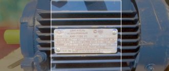
First, let's take a superficial look at what causes the reverse? It is caused by the swapping of two wires, usually in the branded engine box.
In the photo: a sample of a branded box with a star connection.
In the figure above we see that the beginnings of the windings (C1, C3, C5) are free to be connected to the network. The ends of the windings (C2, C4, C6) are connected together.
In the photo: connection with direct connection of the engine to the network.
In the figure, colored circles indicate contacts for connecting phases. Phase A is indicated in yellow, and it is connected to contact C1, phase B (C3) is green, phase C (C5) is yellow.
Observing the above conditions, we will swap any 2 phases and connect as follows. Phase A remains in its place, contact C1, phase B is placed on contact C5, and phase C is placed on contact C3.
In the photo: star connection with reverse connection.
Thus, it turns out that we need 2 starters. One starter is needed to provide direct switching, and the second is needed for reverse switching.
Other engine types
DC electric motors are widely used in the crane industry.
They are manufactured with a power range from 2.5 to 185 kW. Degrees of protection: IP20 – protected assembly, independent airflow, IP23 – completely closed assembly. If the excitation is either mixed or parallel, then these windings do not need to be de-energized. This is due to the technical characteristics of this electric machine, designed for long-term operating conditions.
If the excitation of the device is sequential, then the windings are assembled from two groups. At 220 V they are assembled and connected to each other in series, if 110 V - in parallel, and if the engine is powered by 440 V - in series-parallel with an additional resistor.
The rotation speed is regulated in two ways: by weakening the excitation voltage or increasing it at the armature.
DC electric motors with parallel excitation and a stabilizing winding, according to their characteristics, allow rotation acceleration to be twice the nominal value by reducing the excitation voltage. If this is a low-speed engine type, then you can increase the speed by 2.5 times.
However, it is worth remembering this limitation: for 220 V devices at increased speed, the torque should be no higher than 0.8 Mn, and for 440 V motors - no higher than 0.64 Mn.
Electric motors for cranes have their own characteristics that must be taken into account when installing them on the appropriate mechanisms.
The wound-rotor asynchronous motor has a very wide service area. IM (asynchronous motor) is more often used in controlling high-power motors. Maintenance and control of drives of mills, machine tools, pumps, cranes, smoke exhausters, crushers. An asynchronous motor with a massive rotor makes it possible to connect a variety of technical mechanisms.
Definition of operating mode
Now let’s decide how the engine will work: it is constantly on and turns off when the “stop” button is pressed. As, for example, in drilling, turning, milling machines. Or we need it to work when the “start-right” or “start-left” button is held, as, for example, in winches, electric trolleys, and overhead cranes.
For the first case, it is necessary to draw up a circuit for the reversible start of an asynchronous motor in such a way that the starter is self-shunted, and also protected from accidental activation of the second starter.
Reversing circuit with blocking and protection
Motor reverse
Magnetic starter P3 is turned off. In this case, the existing contact 13NO takes on the role of the main duty officer.
The motor has different designs and switching circuits, but whatever they are, we need only four ends - two from the stator winding and two from the rotor winding, that is, from the commutator brushes. The reverse and forward circuit in this case is very similar to the connection circuit for a three-phase motor, but switching here occurs not of phases, but of the starting winding in one direction or the other.
Only then can you find a suitable scheme.
So, at the moment of switching on, the device consumes a watt. It can be modified, for example, by adding a switch that would swap any two phases.
Advice The main feature of this engine control scheme is the minimum of complex manipulations. There are many varieties, but they all work on the same principle.
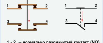
The concept of a normally open contact is formulated in the same way. Therefore, it makes sense to consider them separately.
It is also not recommended to install rheostats near heating elements and not to install them in the most heated parts of the cabinet, for example at the top of the cabinet. Engine control scheme from two and three places
Description of the operation of the above circuit
You may be interested in: Lictor is: the essence of the profession and historical facts
Let's analyze the operation of the circuit diagram of reverse engine starting. The current flows from phase C to the normally closed common button KnS, the “stop” button. After which it passes through a general current relay, which will protect the engine from overloads. Then, when you press the switch “right”, the current passes through the normally closed contact of the KM2 starter. Entering the coil of the KM1 starter, the core is retracted, closing the power contacts, breaking the power to the KM2 starter.
This must be done in order to interrupt the power supply to the second starter and protect the circuits from short circuits. After all, reverse is ensured by the fact that any 2 phases change places. Thus, if you press the “left” KnP button when KM1 is turned on, the start will not occur. Self-shunting is provided by an auxiliary contact, shown under the “right” control panel. When the starter is turned on, this contact is also closed, providing power to the starter coil.
Phase devices
Overhead cranes, as a rule, have asynchronous motors with a wound rotor, for example, MTN.
Such motors provide a smooth start and also allow you to regulate the speed, despite the significant load on the shaft. They are installed on medium, heavy and very heavy duty equipment. The advantage of MTN over DC motors is their lower price and ease of maintenance. If you compare the masses of these engines on overhead cranes, you will see that phase engines are several times lighter. If the total costs of operating squirrel-cage asynchronous machines are taken equal to one, then for phase devices they will be equal to five, and for DC motors - ten. This explains why the vast majority of motors on cranes are three-phase.
For domestic industry, electric motors are produced with different heat resistance of insulation, indicated by a letter in the device model: MTF - 155○C, MTN - 180○C.
Electric machines for bridges, as well as other cranes, the MTN and MTKN series are produced with a rotation speed of 600, 750 and 1 thousand rpm. at 50 Hz, and for a network frequency of 60 Hz - 720, 900 and 1200 rpm. This series is characterized by high overload capacity, increased starting torque at low current and fast acceleration.
MTN motors have increased power due to improved characteristics of insulating materials, compared to previous models of similar electrical machines.
Starting equipment can be powerful resistors, several starters that gradually short-circuit the rotor, and a time relay.
Circuit using powerful resistors, several starters, a gradually short-circuiting rotor, and a time relay
Similar schemes work successfully on overhead cranes. After start-up, the MTH engine is turned on at the full value of the resistance in the rotor circuit. After a certain time set on the time relay, when the starting current drops to the nominal value, the first contactor is turned on, which, as it were, “throws out” part of the resistance and the engine receives additional torque, accelerating to the next value. In each individual case, the number of resistors and surge starters may be different.
When the last starter is turned on, the MTN reaches its full speed and operates as an asynchronous machine with a squirrel-cage rotor. Crane electric motors with a wound rotor can be used for both short-term and permanent operation.
Reduced speed
Modern overhead cranes use an electronic circuit that allows them to achieve a reduced, or “creeping,” speed. This is extremely necessary in cases of loading dangerous or oversized cargo, as well as in cases where very precise loading is required.
For this purpose, thyristors or triacs are used. Receiving voltage from the rotor phase rings, the circuit sets the opening angle of the thyristor according to the specified value. As a result, the driver can adjust the desired speed, if such adjustment is displayed in his cab, or turn on the set value.
Braking
To brake the engine on bridge cranes, and not only on cranes, the dynamic mode is successfully used: a constant voltage having a stationary magnetic field is briefly applied to the stator winding after the power is turned off. This method allows you to increase the accuracy of stopping the mechanism.
This voltage is supplied either through a quenching resistor or using a step-down circuit. After stopping the engine, it must be de-energized.
More about deadlock
The electrical circuit for reversing starting of an asynchronous motor requires an interlock. It is worth understanding that to change the direction of rotation of an asynchronous motor, you need to swap any 2 phases. To do this, the starter inputs are connected directly, and the output is connected crosswise across any 2 phases. If both starters are turned on at the same time, a short circuit will occur, which will most likely burn out the power contact groups on the starters.
You may be interested in: Boyle-Mariotte Law: formula and example problem
In order to avoid a short circuit when installing a reversible motor start, it is necessary to prevent the simultaneous operation of both starters. This is why it is necessary to use an interlocking scheme. When the first starter is turned on, the power to the second starter is interrupted, which prevents its accidental activation, for example, both “start” buttons are pressed simultaneously.
If it turns out that when you press the button that should turn on “rotation to the right,” the engine rotates to the left, and, conversely, when you press “rotation to the left,” the engine rotates to the right, you should not reassemble the entire circuit. Just swap 2 wires at the input - that's all, the problem is solved.
It may happen that this is impossible to do at the input due to some circumstances. In this case, swap the 2 wires in the brand box on the engine. And again the problem is solved. The right spin button will spin right, and the left spin button will spin left.
Single phase network connections
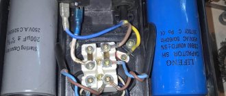
Quite often there is a need to start an asynchronous electric motor in normal domestic conditions, where the presence of a three-phase electrical network is not provided. In such a situation, you need to know how to connect the power unit to a 220V network. In order for the rotor to start rotating, an additional pulse action is required, for which, as a rule, a capacitor with the required capacitive characteristics is included in the electrical circuit.
When using a capacitor, the speed does not change, and the power decreases noticeably. Power losses can vary by up to fifty percent depending on the capacitor capacitance and the specific operating conditions of the electric motor. In addition, not all models of power units can operate in a single-phase power supply. Typically, this possibility is specified in the technical documentation for the product and is indicated on a plate attached to the case.
Of the many available options for connecting an electric motor to a 220V network, two methods are considered standard - “star” and “triangle”. It is recommended that you first read the documentation for a particular electric motor and examine the nameplate with parameters on its body to find out what voltage the windings are designed for and how they can be connected.
In the delta circuit, one contact is connected through a capacitor to the winding, and the other two are output for connection to the power source. In this case, without load, the electric motor shaft will rotate freely at the desired speed, but if it is heavily loaded, the rotation will slow down significantly or stop completely. This problem can be solved if you additionally connect another capacitor to perform only one task - starting the electric motor, after which it discharges and turns off after a couple of seconds.
To connect the starting capacitor to the circuit, a separate momentary start button is usually used. After the rotor spins, it opens the contacts, and the shaft continues to rotate by inertia with the support of the magnetic field of the winding. As such a switch, you can use a relay or a ready-made button with a contact group on a spring, which, when released, raises the contacts and is disconnected from the circuit. To avoid short circuits between turns, it is recommended to use a thermal relay that turns off the additional winding in case of overheating.
In addition, here you can use a centrifugal switch, which opens the circuit when the permissible speed value is exceeded. The plate with contacts is pulled back under the influence of centrifugal force and, when accelerated to a certain number of revolutions, cuts off the power to the electrical installation or redirects the signal to an alternative circuit or control device.
To operate an electric motor connected using the “star” method, a single phase of 220 volts is passed through one of its windings, and a linear voltage of 380 volts is passed through the other two windings. The working capacitor is connected to the output ends of the windings, two of which are output for connection to a single-phase electrical network, and the free end is connected to the capacitor through the mains phase. It is worth noting that the “delta” connection is simpler and the power losses will be less than in the “star” circuit. Therefore, whenever possible, the “triangle” should be used.
In order not only to start the electric motor, but also to provide the ability to reverse movement, the power coming from the capacitor must switch between poles. This can be realized using two switches and one button without fixing the position. One switch will supply voltage to the electric motor power circuit, and the second switch should have a three-position design. In one position the power unit turns off, and in the second and third it changes the polarity of the windings so that the motor rotor rotates in different directions. The non-fixed button is designed to connect a second starter capacitor.
To do this, two outgoing wires from both capacitors are twisted together, and a start button is connected to the other two. The middle output from the three-position switch is connected to the twisted capacitor outputs, and the other two are routed to the motor terminals to supply power to it. Capacitors are also connected to the winding starting outputs, and the power button is mounted in the phase conductor gap. To put this entire structure into operation, voltage is first applied to the main switch and, using a three-position control element, the desired direction of movement of the power unit is indicated. Then the starting capacitor button is pressed and released when the rotor accelerates to normal operating speed. To start the reverse of the electric motor, it is necessary to de-energize it and wait until the rotor comes to a complete stop. Then you can safely move the switch to the reverse position.
Description of the reversible connection diagram for a single-phase motor
In position 1, the mains voltage is transmitted to the left leg of the capacitor, due to which the motor rotates, relatively speaking, to the left. In position 2, power is supplied to the right leg of the capacitor, due to which the motor rotates, relatively speaking, to the right. In the middle position the engine is stopped.
RT is much simpler here. As we can see, here too simultaneous activation by a 3-position switch is excluded. For those who are interested in the question of what will happen if they are turned on at the same time, we will answer simply: the engine will fail.
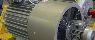
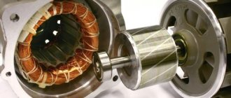
Engine device
The main constants are the stator and rotor. The stator is a cylinder, the composition is sheets of electrical steel, a three-phase winding is laid in the cylinder. It consists of winding wire. Which are connected to each other in the form of a star or triangle depending on the voltage.
The rotor is the main rotating part of engines. Depending on its location, it can be external or internal. This element consists of steel sheets. The core slots are filled with aluminum, which has rods containing end rings. They can be brass or steel, each of them is insulated with a layer of varnish. A gap is formed between the three-phase stator and the rotor. Adjustment of the gap size from 0.30–0.34 mm in devices with low voltage, 1.0–1.6 mm in devices with high constant electrical voltage. The design is called a squirrel cage. For high-power motors, a copper core is used. The contactor starts operating and the engine starts.
There is an additional resistor in the winding circuit of the rotating part of the machine, which is attached using metal-graphite brushes. There are usually two brushes, located on the brush holder. In drives of cranes and centrifuges, a conical movable rotor is used to regulate the robot. Asynchronous motors with a wound rotor are indispensable for the technical requirements of a powerful starting torque. These can be mechanisms such as a crane, a mill, an elevator.
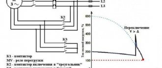
Scheme for switching an electrical circuit from star to delta
Reversing circuit without self-shunting
We will tell you more about the control circuit for starting a reversible asynchronous motor as follows. When you press the KnP “right” button, power is supplied through the normally closed contact of the KnP “left”, and thanks to the mechanical connection, it interrupts the power supply to the KM2 starter, eliminating the possibility of turning on the KM2 when 2 buttons are pressed simultaneously. Next, the current flows to the normally closed contact of the KM2 starter to the coil of the KM1 starter, as a result of which it is triggered, turning on the power to the engine. The reverse is turned on by the “left” switchgear, which also, with its normally closed contacts, breaks the power supply to the KM1 starter, and with its normally open contacts turns on the power supply to the KM2 starter. That, in turn, turns on the power to the motor, but with two phases swapped.
Let's pay attention to the control diagram. Or rather, to deadlock. It's structured a little differently here. The power supply to one starter is not only blocked by the normally closed contact of the opposite starter, but it is also blocked by pressing a button. This is done so that when 2 buttons are pressed simultaneously in those fractions of a second until the starter cuts off the power to the second starter, they do not turn on simultaneously.
Reversing diagram of a three-phase motor in a single-phase network
Since a three-phase asynchronous motor will lack two phases, they need to be compensated with capacitors - starting and running, to which both windings are switched. The torsion of the shaft in one direction or another depends on where to attach the third.
Read also: Grit of diamond wheels for sharpening cutters
The diagram below shows that winding number 3 is connected through a working capacitor to a three-position toggle switch, which is responsible for the forward/reverse engine operating modes. Its other two contacts are combined with windings 2 and 1.
When turning on the engine, you must adhere to the following algorithm of actions:
- Apply power to the circuit through a plug or switch.
- Move the toggle switch to switch operating modes to forward or reverse (reverse).
- Set the power switch to the ON position.
- Press the “Start” button for a time not exceeding three seconds to start the engine.