4.6
Average rating: 4.6
Total ratings received: 79.
4.6
Average rating: 4.6
Total ratings received: 79.
Conductor resistance limits the amount of current in an electrical circuit. The higher the resistance, the lower the current. The conductor resistance can be calculated in two ways: the first method is to use the Ohm's law formula, and the second calculation option involves knowing the geometric dimensions of the conductor and the resistivity of the substance from which it is made.
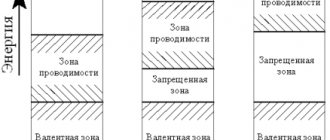
Why does the conductor “resist”?
The voltage U applied to the ends of the conductor creates an electric field inside it, which sets in motion the free electrons of the substance. Electrons, having received additional kinetic energy, begin to move in an orderly manner in one direction, thereby creating an electric current in the circuit.
As they move, electrons collide with neutral and charged atoms that make up the conductor and lose energy. The mass of an atom exceeds the mass of an electron by thousands of times, so their collision leads to a change in the direction of electron motion and a loss of speed (“braking”).
This creates resistance to the flow (increase) of current. Rice. 1. Electric current in a conductor is limited by the collision of electrons with atoms.
Features of active resistance
Resistance in electrical engineering is the most important parameter by which some part of an electrical circuit resists the current passing through it. The formation of this quantity is facilitated by changes in electricity and its transition to other types of energy states.
This phenomenon is typical only for alternating current, under the influence of which active and reactive resistances of cables are formed. This process represents irreversible changes in energy or its transfer and distribution between individual elements of the chain. If changes in electricity become irreversible, then such resistance will be active, and if metabolic processes take place, it becomes reactive. For example, an electric stove produces heat, which is no longer converted back into electrical energy.
This phenomenon fully affects any type of wire and cable. Under the same conditions, they will resist the passage of direct and alternating current differently. This situation arises due to the uneven distribution of alternating current across the cross-section of the conductor, resulting in the formation of the so-called surface effect.
Calculating resistance using Ohm's law
The German physicist Georg Ohm discovered in 1826 that the ratio of the voltage U between the ends of a metal conductor, which is part of an electrical circuit, to the current strength I is a constant value:
$ R={U \over I}=const $ (1),
Where:
U—voltage, V;
I—current strength, A;
R - resistance, Ohm.
This quantity came to be called electrical resistance. Using this formula, you can experimentally determine the value of the unknown resistance.
Rice. 2. Circuit for measuring voltage and current to determine the resistance of a circuit section.
To do this, an ammeter measures the amount of electric current through a resistance, and a voltmeter measures the voltage in a section of the circuit. Next, using formula (1), the value of R is calculated.
The unit of measurement is named after Georg Ohm. An electrical resistance of 1 Ohm has a section of the circuit where, at a current of 1 A, the voltage is 1 V:
$$ 1 Ohm = { 1 V\over 1 A} $$
Determination of active resistance of wires
the active resistance of wires using reference data compiled on the basis of GOST 839-80 - “Bare wires for overhead power lines”, tables 1 - 4. You can find these tables directly in GOST itself, I will give just a few.
It is not recommended to use all known formulas for determining active resistance [L1. p.18], this is due to the fact that the actual cross-section differs from the nominal cross-section, the wires were produced at different times, according to different GOSTs and specifications, and the values of conductivity (ρ) and resistivity (γ) are different:
Where:
- γ – the value of specific conductivity for copper and aluminum wires at a temperature of 20 °C is accepted: for copper wires – 53 m/Ohm*mm2; for aluminum wires – 31.7 m/Ohm*mm2;
- s – nominal wire (cable) cross-section, mm2;
- l – line length, m;
- ρ – the resistivity value is accepted: for copper wires - 0.017-0.018 Ohm*mm2/m; for aluminum wires – 0.026 - 0.028 Ohm*mm2/m, see table 1.14 [L2. p.30].
The active resistance of steel wires cannot be calculated mathematically. Therefore, I recommend using appendices P23 - P25 [L1.] to determine active resistance. p.80,81].
Calculation using resistivity
Conductor resistance can be calculated without measuring voltage and current values. But for this you need to know additional information about the conductor.
Rice. 3. A conductor with cross-section S and length L through which current I flows.
Georg Ohm and other researchers experimentally determined that the resistance of a conductor is directly proportional to the length of the conductor L and inversely proportional to the cross-sectional area of the conductor S. This pattern can be described by the formula for calculating the resistance of the conductor:
$ R = ρ *{ L\over S} $ (2)
The coefficient ρ was called resistivity. This physical quantity reflects the characteristics of a particular substance, which depend on the density of the substance, crystal structure, atomic structure and other internal parameters. It is not necessary to calculate the resistivity of the conductor every time, since for most substances the resistivities are measured and summarized in reference tables, which can be found in paper reference books or in their online versions.
But if such a need arises, then from formula (2) you can obtain the following formula (3), and use it to calculate ρ:
$ ρ = R*{ S\over L } $ (3)
Silver has one of the lowest ρ values, equal to $0.016{Ohm*mm^2\over m}$. This explains the use of such a rather expensive metal for soldering especially important radio components (microcircuits, microprocessors, electronic boards), which should heat up as little as possible during operation.
Calculation of the cross-section of the wire strand depending on the length and load in the line
There are losses in any communication line. A line - a strand of copper wire - has a certain resistance, depending on the length, and, therefore, according to Kirchhoff's law, the voltage must drop across it and a certain power must be released. In broadcast systems, transformer loudspeakers are used as a load. Impedance of a transformer loudspeaker Z is the resistance of the primary winding of the transformer at a frequency of 1 kHz. The resistance of the load or line is a frequency-dependent (complex) quantity, so in this case an elementary estimation calculation is performed for the geometric mean frequency of the entire frequency range (most manufacturers indicate the impedance of a transformer loudspeaker for a frequency of 1 kHz, which corresponds to the middle of the standard frequency range 0.2 - 5 kHz) .
We will solve the problem of determining the cross-section of a wire core in 2 stages, using the known representation of the line and load, in the form of a resistive divider (see Fig. 2).
Rice. 2 - Equivalent load connection diagram at the end of the line
The first stage, in which the entire load is concentrated at the end of the line, will make it possible to simplify the solution of the problem and move on to stage 2, at which the coefficients will be further determined, allowing one to calculate the cross-section of a wire core in a distributed line with arbitrarily specified losses.
Input data for calculation:
Рн – load power in the line, W;
Uin – line input voltage, V;
L – total length of the line, m.
To determine the cross-section of the wire core S, we will use empirical considerations. It is known from electroacoustics that in order to maintain the quality of the transmitted audio signal, the voltage loss in the line should not exceed 10% (this value corresponds to a power loss of approximately 20%, which is considered the norm), which is for a resistive divider (see Fig. 2 ), can be written as: Rl ~ 0.1 Rn, where Rn is the load resistance, Ohm.
Let's substitute this ratio into formula (3):
In broadcast lines, transformer loudspeakers are the load. In this case, the value of the speaker impedance at a certain frequency can be taken as the load resistance Rн. The impedance of a transformer loudspeaker Zgr is the frequency-dependent (complex) resistance of the primary winding of an audio transformer. Most transformer speaker manufacturers specify an impedance value for maximum power at 1kHz.
The impedance of a transformer loudspeaker Zgr can be obtained from 2 well-known formulas:
- Ohm's law for a section of a circuit: J = U / R,
- Load power: P = JU.
When using several parallel-connected transformer loudspeakers as a load, the total impedance Z is calculated by the formula:
Formula (7), which determines the conductivity of the entire circuit, is inconvenient for calculating the total load impedance, especially for a broadcast line with a large number of loudspeakers of different powers. To calculate the total impedance Z of several transformer loudspeakers, it is convenient to use formula (6), in which Pgr must be replaced by the total power of all transformer loudspeakers Pн, consisting of the sum of the powers of individual loudspeakers Pi:
Using the total impedance of the transformer loudspeakers Z (7) as the load resistance Rн and substituting (6) into (5), we obtain a useful formula that determines the cross-section of the wire core S depending on the load power Рн, input voltage Uin and line length L:
Formula (9) is valid for losses in the line not exceeding 10% and provided that the entire load is concentrated at the end of the line (formula 8 is very effective for long lines (L more than 150m). On short lines (L less than 150m) one should not forget about the relationship between the cross section and the current norm (formula 2).
Ohm's law for an alternating current circuit
In an alternating current circuit, in addition to active resistance, resistance can have both capacitive and inductive components. Consider an alternating current circuit consisting of a resistor of resistance R, a capacitor of capacitance C, and a coil of inductance L, connected in series.
The instantaneous current values on all elements of this circuit are the same, and the instantaneous voltage value between the ends of the circuit is equal to the algebraic sum of the instantaneous voltage values on the resistor (UR), capacitor (UC) and inductor (UL).
In order to determine the amplitude (or effective) values of voltage and current, as well as the phase shift between them, it is convenient to use the vector diagram method. Here, the effective values of all voltages and currents are considered as vectors rotating with an angular velocity ω equal to the cyclic frequency of the alternating current, and their instantaneous values are determined by the projections of these vectors onto the horizontal axis. Since the current strength in the circuit is the same, the construction of the vector diagram begins with the vector I¯0, the magnitude of which is equal to the amplitude value of the current strength in the circuit. The direction of this vector can be any. Let us set the angle α = ωt to the horizontal.
The voltage oscillations across the active resistance are in phase with the current oscillations, so the vector U¯0R, the magnitude of which is equal to U0R = I0 × R, coincides in direction with the vector I¯0. The phase shift between the current fluctuations and the voltage fluctuations across the inductive reactance is π/2, with the current being out of phase with the voltage. Therefore, the vector U¯0L, whose modulus is equal to U0L = I0 × ωL, must be rotated relative to the vector I¯0 by an angle π / 2 counterclockwise. The vector U¯0C, whose modulus is equal to I0 / ωC, lags in phase from the vector I¯0 by π / 2, so it must be rotated clockwise by this angle.
In order to find the voltage at the circuit terminals, it is necessary to add three vectors: U¯0 = U¯0R + U¯0L + U¯0C.
First of all, let's add the vectors U¯0R and U¯0C. The modulus of this sum is U'0 = [U¯0R + U¯0C]. Let ωL > 1 / ωC, then: U'0 = I0 × (ωL - 1 / ωC).
Now let's add the vectors U¯0R and U'¯0. The modulus of the vector U¯0 is determined by the Pythagorean theorem: U0² = U0R² + (U0L - U0C)² = I0² × R² + I0² × (ωL - 1 / ωC)². Accordingly, the amplitude (effective) value of the current in an alternating current circuit is equal to the ratio of the amplitude (effective) value of the voltage at the ends of this circuit to its total resistance ( Ohm's law for an alternating current circuit ):
I0 = U0 / √(R² + (ωL - 1 / ωC)²) = U0 / Z, where:
- Z is the total resistance (impedance) of the circuit.
- R is its active resistance.
- ωL - 1 / ωC is the reactance of the alternating current circuit.
- ω = 2 × π × γ - cyclic, angular frequency. γ is the frequency of alternating current.
Impedance for parallel connection Z = 1 / √(1 / R² + 1 / (1 / ωL - ωC)²).
The phase shift between current and voltage is equal to the angle φ between vectors U¯0 and I¯0. According to the graph above, the current lags behind the voltage by an angle φ, with tanφ = (ωL - 1 / ωC) / R.
In order to determine the instantaneous voltage values on the active, capacitive and inductive reactances, it is necessary to project the vectors U¯0R, U¯0L, U¯0C onto straight line AB.
Then:
- UR = I0 × R × sin × (ωt + φ).
- UL = I0 × ωL × sin × (ωt + φ + π / 2).
- UC = (I0 / ωС) × sin × (ωt + φ - π / 2).
If 1 / ωС > ωL, then:
- U'0 = I0 × (1 / ωС - ωL).
- tgφ = (1 / ωC - ωL) / R, and the current is ahead of the voltage in phase by an angle φ.