The final stage of supplying electricity to individual consumers in the power grid
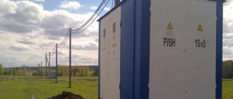
50 kVA distribution transformer on pole
Electricity distribution
This is the final stage in the delivery of electricity;
it carries electricity from the transmission system to individual consumers. The distribution substation connects to the transmission system and reduces the transmission voltage to medium voltage in the range of 2 and 35 kV using transformers.[1] The initial
distribution lines transmit this medium voltage power to distribution transformers located near the customer premises.
Distribution transformers step down the voltage again to the voltage used in lighting, industrial equipment and home appliances. Often from one transformer through secondary
distribution line.
Commercial and residential customers are connected to secondary distribution lines through service interruption. Customers requiring much larger amounts of power can be connected directly to the primary distribution layer or subtransmission layer.[2] General plan for electrical networks.
Voltages and loads are typical for a European network. The transition from transmission to distribution takes place in a substation, which has the following functions:[2]
- Circuit breakers and transfer switches allow you to disconnect a substation from the transmission network or to disconnect distribution lines.
- Transformers step down transmission voltages, 35 kV or more, down to primary distribution voltages. These are medium voltage circuits, usually 600–35000 V.[1]
- From the transformer, the power goes to the busbars which can divide the distribution power in several directions. The bus distributes power through distribution lines that branch out to customers.
Urban distribution is mainly underground, sometimes into common utility channels. Rural distribution is primarily above ground with utility poles, and suburban distribution is a mixture.[1]Closer to the customer, a distribution transformer steps down the power of the primary distribution to a low-voltage secondary circuit, typically 120/240V in the US for residential customers. Energy is supplied to the customer through service interruption and the electric meter. The final loop in an urban system may be less than 15 meters (50 feet), but may be more than 91 meters (300 feet) for a rural customer.[1]
General description of the process
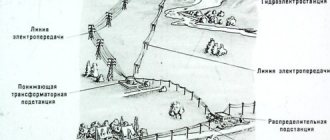
As mentioned earlier, the initial object from which the distribution of electricity begins is today a power station. Nowadays, there are three main types of stations that can supply consumers with electricity. This can be a thermal power plant (TPP), a hydroelectric power station (HPP) and a nuclear power station (NPP). In addition to these main types, there are also solar or wind power plants, however these are used for more localized purposes.
These three types of station are both the source and the first point of distribution of electricity. In order to carry out a process such as the transfer of electrical energy, it is necessary to significantly increase the voltage. The further away the consumer is, the higher the voltage should be. So, the increase can reach up to 1150 kV. An increase in voltage is necessary in order for the current to decrease. In this case, the resistance in the wires also drops. This effect allows current to be transmitted with minimal power loss. In order to increase the voltage to the required value, each station has a step-up transformer. After passing through the section with the transformer, the electric current is transmitted to the central distribution center using power lines. The central distribution station is a central distribution station where direct distribution of electricity is carried out.
Generation and transmission
Simplified scheme of alternating current delivery of electricity from generating stations to consumers termination of service.
Electricity starts at the generating station, where the potential difference can reach 33,000 volts. Usually alternating current is used. Users of large volumes of direct current, such as some railroad electrification systems, telephone exchanges, and industrial processes such as aluminum, use smelting rectifiers to obtain direct current from a publicly available AC source or may have their own generation systems. High-voltage direct current can be beneficial for isolating AC systems or controlling the amount of electricity transmitted. For example, Hydro-Québec has a DC line running from the James Bay region to Boston.[8]
From the generating station it goes to the generating station switchgear where a step-up transformer increases the voltage to a level suitable for transmission from 44 kV to 765 kV. Once in the transmission system, the electricity from each generating station is combined with electricity produced elsewhere. Electricity is consumed immediately after it is produced. It is transmitted at very high speeds, close to the speed of light.
General description of the current path
Facilities such as central distribution centers are already located in close proximity to cities, villages, etc. Not only distribution occurs here, but also voltage reduction to 220 or 110 kV. After this, the electricity is transmitted to substations located within the city.
When passing through such small substations, the voltage drops again, but to 6-10 kV. After this, electricity is transmitted and distributed to transformer points located in different parts of the city. It is also worth noting here that energy transmission within the city to transformer substations is no longer carried out using power lines, but using underground cables. This is much more expedient than using power lines. The transformer point is the last facility where the distribution and transmission of electricity takes place, as well as its reduction for the last time. In such areas, the voltage is reduced to the already familiar 0.4 kV, that is, 380 V. It is then transmitted to private, multi-storey buildings, garage cooperatives, etc.
If we briefly consider the transmission path, it is approximately the following: energy source (10 kV power plant) – step-up transformer up to 110-1150 kV – power line – substation with a step-down transformer – transformer point with voltage reduction up to 10-0.4 kV – consumers (private sector, residential buildings, etc.).
Content
- 1 History 1.1 Introduction of Transformer
- 3.1 Network configurations
- 4.1 Regional variations 4.1.1 220–240 volt systems
Process Features
The production and distribution of electricity, as well as the process of its transmission, has an important feature - all these processes are continuous. In other words, the production of electrical energy coincides in time with the process of its consumption, which is why power stations, networks and receivers are interconnected by such a concept as common mode. This property necessitates the organization of energy systems in order to more efficiently produce and distribute electricity.
It is very important here to understand what such an energy system is. This is a collection of all stations, power lines, substations and other heating networks that are interconnected by such a property as common mode, as well as a single process of producing electrical energy. In addition, the transformation and distribution processes in these areas are carried out under the overall control of this entire system.
The main operating unit in such systems is the electrical installation. This equipment is designed for the production, conversion, transmission and distribution of electricity. This energy is obtained by electrical receivers. As for the installations themselves, depending on the operating voltage, they are divided into two classes. The first category works with voltages up to 1000 V, and the second, on the contrary, with voltages from 1000 V and above.
In addition, there are also special devices for receiving, transmitting and distributing electricity - switchgear (RU). This is an electrical installation that consists of such structural elements as busbars and connecting busbars, switching and protection devices, automation, telemechanics, measuring instruments and auxiliary devices. These units are also divided into two categories. The first is open devices, which can be used outdoors, and closed ones, used only when located inside a building. As for the operation of such devices within the city, in most cases it is the second option that is used.
One of the last frontiers of the power transmission and distribution system is the substation. This is an object that consists of switchgear up to 1000 V and from 1000 V, as well as power transformers and other auxiliary units.
Story
Further information: History of Electricity Transmission
In the late 1870s and early 1880s, arc lamp lighting was introduced, used outdoors or in large indoor spaces, such as this Brush Electric Company system installed in 1880 in New York City.
Electrical distribution became necessary only in the 1880s, when electricity began to be generated in power stations. Before this, electricity was usually produced where it was used. The first electrical distribution systems installed in cities in Europe and the USA were used for lighting: arc lighting runs on very high voltage (about 3000 volts), alternating current (AC) or direct current (DC) and incandescent lamps runs on low voltage (100 volts) DC.[3] Both have replaced gas lighting with systems in which arc lighting occupies a larger area and street lighting, and incandescent lighting is replacing gas lighting for businesses and homes.
Due to the high voltage used in arc lighting, a single generating station could provide a long string of lights up to 7 miles (11 km).[4] Each doubling of the voltage will allow the same size cable to transmit the same amount of power, four times the distance for a given power loss. Indoor lighting systems with incandescent DC lamps, such as the first Edison Pearl Street Station installed in 1882, had difficulty supplying customers more than a mile away. This was due to the fact that the entire system used a low voltage 110V system, from generators to end use. Edison's DC system required thick copper conductors, and generating stations had to be located within approximately 1.5 miles (2.4 km) of the furthest customer to avoid prohibitively large and expensive wires.
Transformer Introduction
Transmitting power over long distances at high voltage and then stepping it down to a lower voltage for lighting has become a recognized engineering obstacle to power distribution, with many less than satisfactory solutions tested by lighting companies. The mid-1880s saw a breakthrough in the development of functional transformers, which allowed alternating voltages to be "boosted" to much higher transmission voltages and then dropped to a lower final voltage. With much lower transmission costs and greater economies of scale due to the presence of large power plants powering entire cities and regions, the use of alternating current quickly spread.
In the US, the competition between direct and alternating current took a personal turn in the late 1880s in the form of the "War of the Currents" when Thomas Edison began attacking George Westinghouse and his development of the first AC transformer systems in the US, pointing out all the deaths caused by high voltage systems AC power for many years, and stating that any AC system is inherently dangerous.[5] Edison's propaganda campaign was short-lived: his company switched to AC in 1892.
AC has become the dominant form of power transmission with innovations in Europe and the US in electric motor design and the development of universal system
ability to connect large numbers of legacy systems to large AC networks.[6][7]
In the first half of the 20th century, in many places the electric power industry was vertically integrated, meaning that one company handled generation, transmission, distribution, metering, and billing. Beginning in the 1970s and 1980s, countries began a process of deregulation and privatization, leading to electricity markets. The distribution system will remain regulated, but the generation, retail, and sometimes transmission systems have been transformed into competitive markets.
Consideration of power distribution scheme
In order to consider in more detail the process of production, transmission and distribution of electricity, we can take as an example the structural diagram of the supply of electrical energy to a city.
In this case, the process begins with the generators at the state regional power plant (state district power plant) generating a voltage of 6, 10 or 20 kV. In the presence of such voltage, transmitting it over a distance of more than 4-6 km is not economical, since there will be large losses. In order to significantly reduce power loss, a power transformer is included in the transmission line, which is designed to increase the voltage to values such as 35, 110, 150, 220, 330, 500, 750 kV. The value is selected depending on how far away the consumer is. This is followed by a point for reducing electrical energy, which is presented in the form of a step-down substation located within the city. The voltage is reduced to 6-10 kV. It is worth adding here that such a substation consists of two parts. The first part of the open type is designed for voltage 110-220 kV. The second part is closed and includes a power distribution device (PD), designed for a voltage of 6-10 kV.
Secondary distribution
World map of network voltage and frequency
Main article: Low voltage network
Electricity is supplied at a frequency of 50 or 60 Hz, depending on the region. Supplied to domestic buyers as single-phase electricity. In some countries, as in Europe, a three-phase proposal may be available for larger sites. Seen from an oscilloscope, a North American household power supply would appear as a sine wave, oscillating between -170 volts and 170 volts, giving an effective voltage of 120 volts RMS.[18] Three-phase electrical power is more efficient in terms of the power transferred to each used cable, and is more suitable for running large electric motors. Some large European appliances can be powered by a three-phase power supply, such as electric stoves and clothes dryers.
A ground connection is usually provided for the customer's system as well as for utility-owned equipment. The purpose of connecting the customer's system to ground is to limit the voltage that may occur when high voltage conductors drop onto low voltage conductors, which are typically mounted lower to ground, or if a distribution transformer fails. Grounding systems can be TT, TN-S, TN-CS or TN-C.
Regional variations
220–240 volt system
Most of the world uses single-phase 220 or 230 V at 50 Hz or three-phase 400 V for residential and light industrial applications. In this system, the primary distribution network supplies multiple substations per zone, and the 230V/400V power from each substation is directly distributed to end users in an area with a radius of less than 1 km. Three live wires and a neutral are connected to the building for three-phase power. Single-phase distribution with one live wire and neutral is used domestically where the overall loads are small. In Europe, electricity is typically distributed for industrial and domestic use on a three-phase, four-wire system. This gives a phase-to-phase voltage of 400 volts operating and a single-phase voltage of 230 volts between any one phase and neutral. In the UK, a typical urban or suburban low voltage substation typically has a capacity of between 150 kVA and 1 MVA and supplies an entire area of several hundred houses. Transformers are typically rated for an average load of 1 to 2 kW per house, and fuses and cabling are sized to allow any property to draw a peak load of perhaps ten times this. For industrial consumers - three-phase. 690/400 volts are also available or can be created locally.[19] Large industrial customers have their own input transformer(s) from 11 kV to 220 kV.
100–120 volt systems
Most of America uses 60 Hz AC, 120/240 V. split phase system domestically and three phase for larger installations. Transformers in North America typically supply 240 volts to homes, similar to 230 volts in Europe. This is a split phase, which allows you to use 120 volts in the house.
Useful frequencies in Japan are 50 Hz and 60 Hz.
In the electric power industry in Japan, the standard voltage is 100 V at AC frequencies of 50 and 60 Hz. Some parts of the country use 50 Hz and other parts use 60 Hz.[20] This is a relic from the 1890s. Some local providers in Tokyo imported German 50Hz equipment, while local electricity suppliers in Osaka imported 60Hz generators from the US. The networks grew until eventually the entire country was connected. Today the frequency is 50 Hz in Eastern Japan (including Tokyo, Yokohama, Tohoku, and Hokkaido) and 60 Hz in Western Japan (including Nagoya, Osaka, Kyoto, Hiroshima, Shikoku, and Kyushu).[21]
Most household appliances operate at any frequency. The incompatibility problem came to light when the 2011 Tōhoku Earthquake and Tsunami knocked out about a third of the east's power, and power in the west could not be fully shared with the east since the country does not have a common frequency.[20]
There are four high voltage direct current (HVDC) converter stations that move electricity across Japan's AC frequency boundary. Shin Shinano is a back-to-back HVDC facility in Japan that constitutes one of four frequency converter stations connecting Japan's western and eastern power grids. The other three are in Higashi-Shimizu, Minami-Fukumitsu and Sakuma Dam. Together they can move up to 1.2 GW of power to the east or west.[22]
240-volt systems and 120-volt outlets
Most modern homes in North America are designed to receive 240 volts from a transformer, and by using two-phase electrical power, can have either 120-volt or 240-volt outlets. 120V is typically used for lighting and most wall outlets. 240-volt outlets are typically designed to service the oven and stove, water heater, and clothes dryer (if they are electric and not natural gas). Sometimes a 240-volt outlet is installed in the garage for equipment or for charging an electric car.
Sections of the electricity supply scheme
In addition to those devices that were listed earlier, the energy supply system also includes such objects as a supply cable line - PKL, a distribution cable line - RKL, a cable line with a voltage of 0.4 kV - KL, an input-type switchgear in a residential building – ASU, the main step-down substation at the plant – GPP, an electricity distribution cabinet or a switchboard device, located in the plant workshop, and designed for 0.4 kV.
Also in the circuit there may be such a section as the power center - the CPU. It is important to note here that this object can be represented in terms of two different devices. This could be a secondary voltage switchgear at a step-down substation. In addition, it will also include a device that will perform the functions of voltage regulation and subsequent delivery to consumers. The second design option is a transformer for the transmission and distribution of electricity, or a generator voltage distribution device directly at the power station.
It is worth noting that the CPU is always connected to the distribution point of the distribution center. The line that connects these two objects has no distribution of electrical energy along its entire length. Such lines are usually called cable lines.
Today, the energy network can use equipment such as KTP - a complete transformer substation. It consists of several transformers, a distribution or input device, designed to operate with a voltage of 6-10 kV. The kit also includes a 0.4 kV switchgear. All these devices are connected to each other by conductors, and the kit is supplied either ready-made or ready for assembly. Reception and distribution of electricity can also occur on high structures or on power transmission towers. Such structures are called either pole-mounted or mast-mounted transformer substations (MTS).
external reference
- Mexico Network Code Technical Requirements
- Neutral conductor and its protection in low voltage distribution network
- Experience in the evaluation of polymer insulators for medium voltage distribution networks in a natural laboratory
- Geographic information about energy in Argentina.
| authoritative control |
|
- Datos: Q844861
- Multimedia: Electrical distribution
First category of electrical receivers
Today there are three categories of electrical receivers, which differ in the degree of reliability.
The first category of electrical receivers includes those objects where, if the power supply is disrupted, quite serious problems arise. The latter include the following: a threat to human life, severe damage to the national economy, damage to expensive equipment from the main group, massive defective products, destruction of the established technological process for obtaining and distributing electricity, possible disruption of the operation of important elements of public utilities. Such electrical receivers include buildings with large crowds of people, for example, a theater, supermarket, department store, etc. Electrified transport (metro, trolleybus, tram) also belongs to this group.
As for the supply of electricity to these structures, they must be provided with electricity from two sources that are independent of each other. Disconnection of such buildings from the network is allowed only for the period during which the backup power source will be started. In other words, the power distribution system must provide for a quick transition from one source to another in the event of an emergency. In this case, an independent power source is considered to be one on which the voltage will remain even if it disappears on other sources powering the same electrical receiver.
The first category also includes devices that must be powered from three independent sources at once. This is a special group whose work must be ensured uninterrupted. That is, disconnection from the power supply is not allowed even while the emergency source is turned on. Most often, this group includes receivers whose failure entails a threat to human life (explosion, fire, etc.).
Second and third categories of receivers
Electricity distribution systems with the connection of the second category of electrical receivers include such equipment, if the power is turned off, there will be massive downtime of working mechanisms and industrial vehicles, undersupply of products, as well as disruption of the activities of a large number of people living both within the city and outside it. outside. This group of electrical consumers includes residential buildings above the 4th floor, schools and hospitals, power plants, the power outage of which will not result in the failure of expensive equipment, as well as other groups of electrical consumers with a total load of 400 to 10,000 kV.
Energy sources of this category should be two independent stations. In addition, disconnection from the main power source of these objects is allowed until the personnel on duty puts the backup source into operation, or the duty team of workers at the nearest power supply station does this.
As for the third category of receivers, these include all the remaining devices that can be powered by just 1 power source. In addition, such receivers may be disconnected from the network during repairs or replacement of damaged equipment for a period of no more than 24 hours.
Schematic diagram of the supply and distribution of electrical energy
Control of the distribution of electricity and its transmission from source to receiver of the third category within the city is most easily accomplished using a radial dead-end circuit. However, such a circuit has one significant drawback, which is that if any one element of the system fails, all receivers connected to such a circuit will be left without power. This will continue until the damaged section of the chain is replaced. Due to this drawback, it is not recommended to use such a connection scheme.
If we talk about the connection and energy distribution diagram for receivers of the second and third categories, then here you can use a ring circuit diagram. With this connection, if there is a failure in the operation of one of the power lines, you can restore the power supply to all receivers connected to such a network manually by turning off the power from the main source and starting the backup one. The ring circuit differs from the radial circuit in that it has special sections in which disconnectors or switches are located in the off mode. If the main power source is damaged, they can be turned on to restore supply, but from the backup line. This will also serve as a good advantage if any repair work needs to be carried out on the main line. A break in the power supply to such a line is allowed for a period of about two hours. This time is enough to turn off the damaged main power source and connect the backup one to the network so that it distributes electricity.
There is an even more reliable way to connect and distribute energy - this is a circuit with parallel connection of two supply lines or the introduction of automatic connection of a backup source. With such a scheme, the damaged line will be disconnected from the general distribution system using two switches located at each end of the line. In this case, the supply of electricity will be carried out in a still uninterrupted mode, but through the second line. This scheme is relevant for receivers of the second category.
Electrical connection diagrams in the power supply system
ELECTRICAL CONNECTION DIAGRAMS IN THE POWER SUPPLY SYSTEM
5.1. General information
The facility's power supply system consists of supply, distribution, transformer and converter substations and cable and overhead networks connecting them, as well as conductors.
Electrical connection diagrams for electrical installations are made for primary and secondary circuits.
Primary circuits include the main circuits of electrical installations through which electrical energy is supplied to consumers; their circuits are made single-line and three-line.
In single-line diagrams, the three phases of an installation and its equipment are conventionally depicted for one phase. Three-line diagrams indicate connections for all three phases, as well as secondary circuits! The complete diagram is cumbersome, so it is performed only for individual elements of the installation.
Secondary circuits include circuits used to connect secondary electrical equipment - measuring instruments, control and alarm devices and devices, relay protection and automation devices.
This section discusses primary circuits in a single line drawing.
5.2. Selection of nominal voltages
The choice of voltages for sections of the facility's electrical network is determined by technical and economic comparison of options. When choosing the final design decision made on the basis of comparison of options, it is necessary to give preference to the option with a higher voltage. In most cases, the designer determines the voltages within the two closest nominal voltage values on the scale, for which the options are compared. In some cases, the initial data for design lead to an unambiguous determination of the rated voltage without detailed technical and economic calculations.
When choosing the rated voltage of the external section of the network, the existing voltages of possible power sources of the power system, the distance from these sources to the enterprise and the load of the enterprise as a whole are taken into account.
In the supply and distribution networks of small and medium-sized enterprises and cities, rated voltages of 6 and 10 kV are used. As a rule, a voltage of 10 kV should be used as it is more economical than a voltage of 6 kV. A voltage of 6 kV is used when there is a predominance of electrical receivers with a voltage of 6 kV at the facility. In a number of cases, power supply to power receivers with a voltage of 6 kV is carried out via supply lines with a voltage of 10 kV, followed by transformation to a voltage of 6 kV directly for these power receivers.
Voltage 660V as an intra-shop voltage is advisable at those enterprises where, due to the conditions of the location of the workshop technological equipment or the environment, it is impossible or difficult to bring the workshop transformer substations closer to the electrical receivers they feed. Voltage 660V is also advisable in enterprises with a high specific density of electrical loads, power concentration and a large number of 200 kW motors. The most appropriate combination of voltage is 660V with a primary voltage of 10 kV. It must be taken into account that when using a voltage of 660V, there is also a need for networks with a voltage of 380V to power small electric motors and lighting installations. The most widely used and main voltage is 380/220 V.
5.3.
Power sources and points for receiving electricity from objects with voltages above 1 kV
5.3.1. Power sources and requirements for power supply reliability
The facility can be supplied with electricity from its own power plant (CHP), energy system, as well as from the energy system if it has its own power plant.
The requirements for the reliability of power supply from power sources are determined by the power consumption of the facility and its type.
Receivers of electrical energy with regard to ensuring the reliability of power supply are divided into several categories.
From the first category of electrical receivers, j a special group (zero category) of electrical receivers is distinguished, the uninterrupted operation of which is necessary for an accident-free shutdown of production in order to prevent a threat to human life, explosions, fires and damage to expensive equipment. For example, electrical receivers of category zero include hospital operating rooms and emergency lighting.
Second category
- electrical receivers, interruption of power supply, which leads to massive shortages of products, massive downtime of workers and machinery. The permissible duration interval of a power supply interruption for power receivers of the second category is no more than 30 minutes.
An example of electrical receivers of the second category in industrial installations are receivers in rolling shops, main mechanical engineering shops, textile and pulp and paper industries. Schools, children's institutions and residential buildings up to five floors, etc. are usually classified as reception centers of the second category.
Third category
- all other electrical receivers that do not fit the definition of the first and second categories. This category includes auxiliary production installations and non-essential warehouses.
Electrical receivers of the first category must be provided with electricity from two independent power sources; when one of them is turned off, switching to the backup one must be carried out automatically. According to the definition of PUE, independent power sources are those that retain voltage when it disappears from other sources that supply these power receivers. According to the PUE, two sections or bus systems of one or two power plants or substations can be classified as independent sources, subject to the following conditions:
each of these sections or bus systems is powered from independent sources;
The bus sections are not connected to each other or have a connection that is automatically switched off if the normal operation of one of the bus sections is disrupted.
To supply power to power receivers of a special group, an additional third power source must be provided, the power of which must ensure trouble-free shutdown of the process.
It is recommended to provide power receivers of the second category from two independent power sources; switching cannot be carried out automatically.
Power supply to power receivers of the third category can be provided from a single source, provided that power supply interruptions necessary for the repair and replacement of damaged equipment do not exceed one day.
5.3.2.
Connection diagrams for power supplies
Power supply from your own power plant
(Fig. 5.1). When your own power plant is located close to objects and when the voltages of the distribution network and the power plant generators coincide, transformers are connected to the buses of the power plant switchgears either directly or using power lines.
Electricity supply from the energy system in the absence of
its own power plant
(Fig. 5.2 and 5.3). Depending on the voltage of the power source, power supply is carried out in two ways: according to the diagram shown in Fig. 5.2, at voltage 6…20 kV; according to the diagram presented in Fig. 5.3, at voltage iV. In the diagrams indicated and below, disconnectors and reactors are not shown. The diagrams presented in Fig. 5.2 and 5.3 are applicable if the enterprise is located at a distance of no more than 5...10 km from the system substation.
5.3.3. Types of electrical substations
The number and type of electricity receiving points (substations) depend on the power consumed by the power supply facility and the nature of the location of electricity consumers on the territory of the facility. With a relatively compact location of consumers and the absence of special requirements for the reliability of power supply, all electricity from the power source can be supplied to one transformer (TS) or distribution substation (DS). If consumers are scattered and there are increased requirements for uninterrupted power supply, power should be supplied to two or more substations.
When the power source is close to the facility and the power it consumes is within the capacity of 6 and 10 kV lines, electricity is supplied to the distribution substation RP or to the main distribution substation (MDS). RP are used to receive and distribute electricity without its conversion or transformation.
From the distribution point, electricity is supplied to the transformer substations and to power receivers with voltages above 1 kV, i.e. in this case, the voltages of the supply and distribution networks coincide.
If the facility consumes significant (more than 40 MB • A) power, and the power source is remote, then electricity is received at the main distribution substations or at the main step-down substations.
Nodal distribution substation
(URP) is the central substation of an object with a voltage of 35 kV, which receives power from the power system and distributes it to deep input substations on the territory of the object.
A main step-down substation
(MSS) is a substation that receives power directly from the district power system and distributes energy at a lower voltage (6 or 10 kV) throughout the facility.
Deep input substation
(PGV) is a substation for voltage 35...220 kV, made according to simplified switching circuits at primary voltage, receiving power directly from the power system or from the URP. PGV is usually intended to power a separate facility (large workshop) or area of the enterprise.
5.4. Principles for choosing a power distribution scheme
The power supply system can be made in several options, from which the optimal one is selected. When choosing it, the degree of reliability, ensuring the quality of electricity, convenience and safety of operation, and the possibility of using advanced methods of electrical installation work are taken into account.
Basic principles for constructing facility diagrams:
maximum proximity of 35 kV high voltage sources to consumer electrical installations with deep input substations located next to energy-intensive production buildings;
Power backup for certain categories of consumers must be included in the circuit and elements of the power supply system. To do this, lines, transformers and switching devices must carry a constant load in normal mode, and in post-emergency mode, after disconnecting the damaged sections, take over the power supply to the consumers remaining in operation, taking into account the overloads permissible for these elements;
sectioning the buses of all parts of the energy distribution system, and if consumers of the first and second categories predominate, installing automatic transfer switches on them.
The schemes are built according to the level principle. Typically two or three levels are used. The first level of electricity distribution is the network between the facility’s power source and the PGV, if the distribution is carried out at a voltage of 110...220 kV, or between the PP and RP voltage
6kV if distribution occurs at a voltage of 6kV.
The second level of electricity distribution is the network between the distribution center (or secondary voltage switchgear of the PGV) and the transformer substations (or individual high-voltage electrical receivers).
At small and some medium-sized facilities, only one level of energy distribution is often used between the power supply center from the system and energy receiving points (TPs or high-voltage electrical receivers).
5.5. Diagrams of electrical networks inside the facility at a voltage of 6 kV
Electrical networks inside the facility are carried out according to main, radial or mixed schemes.
Radial power distribution schemes are used in cases where receiving points are located in different directions from the power center. They can be two - or! single-stage. At small facilities and to power large concentrated consumers, single-stage circuits are used. Two-stage radial schemes with intermediate RP are carried out for large and medium-sized objects with departments located over a large territory. If there are consumers of the first and second categories, the RP and TP are powered by at least two separately operating lines. It is allowed to supply electrical receivers of the second category via one line consisting of at least two cables.
With two-transformer substations, each transformer is powered by a separate line according to the line-transformer block diagram. The capacity of the unit in post-emergency mode is calculated based on the category of consumers supplied.
With single-transformer substations, mutual power backup of small groups of first category receivers is carried out using cable or bus jumpers on the secondary voltage between adjacent substations.
All switching equipment is installed on the RP or GPP, and on the TP powered from them, predominantly blind connection of transformers is provided. Sometimes TP transformers are connected through a load switch and a disconnector.
A radial circuit with an intermediate RP, in which the above conditions are met, is shown in Fig. 5.4.
The radial power supply circuit has great flexibility and ease of operation, since damage or repair of one line affects the operation of only one consumer.
6...10 kV main circuits are used for linear (“ordered”) placement of substations on the territory of a facility, when lines from the power center to receiving points can be laid without significant reverse directions. Trunk circuits have the following advantages: better cable loading in normal mode, fewer cameras on the distribution center. The disadvantages of trunk circuits include the complication of switching circuits when connecting a transformer substations and the simultaneous disconnection of several consumers powered by the trunk if it is damaged.
The number of transformers connected to one main line usually does not exceed two or three with a transformer power of 1000...2500 kVA and four or five with a power of 250...630 kVA.
Trunk circuits are made single and double, with one-sided and two-sided power supply.
Single lines without redundancy (Fig. 5.5, a) are used in cases where the disconnection of one consumer makes it necessary, according to the production technology, to disconnect all other consumers (for example, continuous technological lines). With cable mains, their route must be accessible for repair at any time of the year, which is possible when laid in channels, tunnels, etc. The reliability of a circuit with single mains can be increased if the single-transformer substations fed by them are located in such a way that it is possible to carry out partial redundancy for low voltage connections between nearby substations. In Fig. Figure 5.6 shows a diagram in which closely located transformer substations are powered by different single mains with redundancy over low voltage connections. Such main circuits can also be used for consumers of the first category, if their power does not exceed 15...20% of the total load of transformers; the transformers are connected to different mains connected to different sections of the distribution switchgear or switchgear. Single lines with blind taps, i.e., without disconnectors at the inlet and outlet of the line, are used mainly on overhead lines. On cable lines, blind connection can only be used to power non-essential substations with a capacity of no more than 400 kVA.
Schemes with double (“through”) highways (see Fig. 5.5,6)
are used to power responsible and technologically weakly interconnected consumers of one facility. Installation of disconnectors at the entrance and exit of the main line is not required.
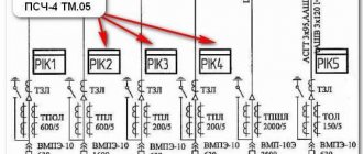
At large enterprises, two or three main current conductors are used (Fig. 5.7), laid along different routes through the areas where the main electrical loads are located. At smaller enterprises, circuits with single double-circuit current conductors are used. Reactors are installed on branches from conductors to distribution substations to limit the short circuit power to the value of the switched power of VMP type circuit breakers. Each transformer feeds two current conductors crosswise, i.e., different circuits of each current conductor are powered by different transformers.
Single and double mains (Fig. 5.8) with two-way power supply (“counter” mains) are used when powered from two independent sources required by the conditions for ensuring reliable power supply for consumers of the first and second categories. When both sources are used in normal mode, the main line is divided approximately in the middle at one of the intermediate substations. Sectional switches are normally open and equipped with an ATS device.
Mixed power supply schemes, combining the principles of radial and main power distribution systems, are most widespread at large facilities. For example, at the first level radial schemes are usually used. Further distribution of energy from the distribution point to the workshop transformer substations and high-voltage motors at such facilities is carried out using both radial and mainline schemes.
The degree of reservation is determined by the category of consumers. Thus, consumers of the first category must be provided with power from two independent sources. As a second power source, not only sectionalized busbars of power plants or substations can be used, but also jumpers in low-voltage networks if they supply power from the nearest distribution point that has independent power supply from an automatic transfer switch.
For especially critical consumers classified as a special group of the first category, power supply must be provided from three independent sources. Each of the two main sources must fully supply power to the consumer, and the third independent source must have a minimum power for an accident-free shutdown of production. The third independent source can be, for example, a diesel station, which, when one of the two independent sources is turned off, turns on at idle and is in a “hot” standby mode. To avoid overloading the third source, it is necessary to disconnect the remaining consumers before introducing the third source.
In large cities, a distribution network with a voltage of 6...10 kV, made according to a loop circuit, has become widespread.
In Fig. Figure 5.9 shows a loop line powered by one RP. In normal mode, the loop line is opened by disconnector R-1 and each main line is powered independently from the RP. If any section on one of the lines is damaged, the switch on the head section B-1 or B-2 is automatically turned off and the power to all consumers connected to the damaged line is cut off. Having found the location of the damage, this section is manually switched off with disconnectors, closing the A-B jumper with disconnector R-1, and the power supply to the consumers is restored. The most severe case for such a line will be damage at point K, since the power supply to the entire load is t
post-emergency mode will be carried out along one line. Electrical equipment must be checked for heating in post-emergency mode. In addition, under these conditions it is necessary to check the line for voltage loss. The number of transformers connected to one line should not be more than five or six. The backup jumper must be energized even when the circuit is open.
A schematic diagram of connecting a loop line to two RPs is shown in Fig. 5.10. The location of the line opening can be chosen arbitrarily, but to obtain minimal power losses it is desirable that it be at the current separation point. Each line is connected by its head sections to two distribution centers. Each part of the line from the distribution point to the current divider feeds a certain number of transformer substations. The diagram shows that TP-1 and TP-2 are connected to part of line L-2 from RP-1 to current divider R4, and TP-3 is connected to part of line L-2 from RP-2 to current divider P4. Thus, both parts L-2 lines are constantly under voltage. In the event of an accident on any section of the L-2 line, for example at point K, the relay protection installed on RP-1 will turn off the B-2 switch and the substations connected to the line from RP-1 to the current divider P4, i.e. TP-1 and TP-2 will stop supplying electricity to consumers. To restore power to TP-1 and TP2, the duty personnel of the city electrical network turns off the emergency section of the line with disconnectors P2 and P3 and then turns on disconnector P4, thereby transferring TP-2 to power from RP-2. After eliminating the accident on the line, TP-2 will again receive power from RP-1. As can be seen from the diagram, lines L-1 and L-2 reserve transformer substations on the side of 6...10 kV lines. However, if the transformer in any TP is damaged (in this case, regardless of the TP redundancy along 6...10 kV lines), the power supply to consumers connected to this substation will stop. Taking this circumstance into account, the scheme provides for redundancy of low voltage switchgears through an electrical network with a voltage of 0.4 kV using connecting points (SP) C1, C2, C3 and C4. In normal mode, all incoming lines with a voltage of 0.4 kV in the joint venture are disconnected and each substation, isolated from each other, supplies a certain area of consumers. In case of failure, for example, of the transformer in TS-2, it is enough to close the connecting lines in C1 and C2, and consumers connected to TS-2 will receive power from TS-1 and TS-5. Such redundancy is possible provided that the power of the transformers is selected taking into account their overload capacity in post-emergency conditions.
It should be remembered that the loop network does not provide uninterrupted power supply to consumers: if any section of the loop network is damaged, some consumers are disconnected for the time required to disconnect the damaged section and transfer it to power from undamaged sections of the network.
To increase the reliability of power supply, networks with an ATS device on the sectional switch of the switchgear have become widespread.
5.6. Schemes of urban distribution networks with voltage up to 1 kV
To power consumers of the third category, radial non-redundant or main circuits with one-way power supply are used. The main circuit can be used to power residential buildings and other consumers with relatively low power.
In Fig. 5.11 shows the most common diagrams of distribution networks with voltages up to 1 kV. From diagrams 5.11, and
and 5.11,
6
it is clear that distribution networks built according to radial and main circuits provide power to consumers only in normal mode. If the network is damaged in any section or in the event of a short circuit, the power supply to all consumers connected to the network is interrupted. Power can only be restored after repairing the damaged network element.
Rice. 5.12. Power supply circuit with voltage up to 1 kV for a residential building above 16 floors
The most widespread in urban networks is the loop circuit, which is widely used to supply power to consumers of the second category. In Fig. 5.11, in
A loop diagram with a backup jumper is shown, which is switched on in case of damage in one of the network sections.
Power supply to electrical receivers of buildings with a height of 9...14 floors is carried out according to a radial loop circuit (Fig. 5.11, d
).
A loop backbone circuit with two mutually redundant cable lines with switches at the consumer inputs is shown in Fig. 5.11, d
.
When supplying power to buildings higher than 16 floors with electrical receivers of the first category, such as elevators, fire pumps, emergency lighting, etc., a circuit with automatic backup is used (Fig. 5.12). Under normal conditions, power receivers of the first category are powered, for example, via line L-2 from transformer T-2. If line L-2 or transformer T-2 fails, power receivers automatically switch to power from line L-1 and transformer T-2, which ensures uninterrupted power supply.
To supply power to multi-storey and multi-section residential buildings, as well as to power large free-standing restaurants and shops, a circuit with three redundant cables is used (Fig. 5.13). As can be seen from the diagram, each cable reserves only one of the supply lines.
5.7. Schemes of workshop electrical networks with voltage up to 1 kV
The main condition for the rational design of the power supply network of an industrial facility is the principle of equal reliability of the supply line (with all devices) and one power receiver of the technological unit receiving one power supply from this line. Therefore, it makes no sense, for example, to power one electric motor of a technological unit via two mutually redundant lines. If a technological unit has several electrical receivers that carry out a single technological process connected by a group of machines, and the loss of power to any of these electrical receivers necessitates stopping the operation of the entire unit, then in such cases the reliability of the power supply is fully ensured with a main power supply (Fig. 5.14). In some cases, when a high degree of reliability of power supply to electrical receivers in a continuous technological process is required, double-sided power supply to the main line is used (Fig. 5.15).
Main power supply circuits are widely used not only to power many electrical receivers of one technological unit, but also a large number of relatively small receivers that are not connected by a single technological process. Such consumers include metal-cutting machines in metal machining shops and other consumers distributed relatively evenly over the workshop area. 1 Trunk circuits make it possible to avoid the use of a bulky and expensive switchgear or switchboard; in this case, it is possible to use a transformer-trunk block circuit, where industrially manufactured busbars (busbars) are used as the supply line. Backbone circuits made by busbars provide high reliability, flexibility and versatility of workshop networks, which allows technologists to move equipment within the workshop without significant alterations to electrical networks.
To power a large number of electrical receivers of relatively low power, relatively evenly distributed over the workshop area, circuits with two types of main lines are used: supply and distribution (Fig. 5.16). The supply, or main, lines are connected to the busbars of transformer substation cabinets, specially designed for main circuits. The distribution lines to which electrical receivers are directly connected receive power from the main supply lines or directly from the buses of a complete transformer substation (CTS), if the main lines are not used (Fig. 5.17).
The smallest possible number of individual electrical receivers are connected to the main supply lines. This increases the reliability of the entire power system.
One should take into account the disadvantage of main circuits, which is that if the main line is damaged, all electrical receivers powered by it are simultaneously switched off. This disadvantage is noticeable when there are separate large consumers in the workshop that are not connected by a single continuous technological process. Rice. 5.17. Diagram of distribution lines connected directly to the busbars of the complete transformer
substations
Radial power supply schemes are characterized by the fact that | From the power source, for example from a package transformer substation, lines depart directly from powerful power receivers or individual distribution points, from which smaller power receivers are fed by independent lines (Fig. 5.18).
Radial circuits provide high reliability of power supply to individual consumers, since accidents are localized by turning off the circuit breaker of the damaged line and do not affect other lines.
All consumers can lose power only if there is damage to the busbars of the PTS, which is unlikely due to the fairly reliable design of the cabinets of these PTS.
Focusing on the PTS of control and protection devices for individual connections makes it easier to solve automation problems in the electricity distribution system at voltages up to 1 kV than with a dispersed arrangement of devices, which is the case with a mainline system. Radial circuits of supply networks with switchgears or switchboards should be used if there are several fairly powerful consumers in the workshop that are not connected by a single technological process or with each other so much that their main supply is impractical.
Such consumers may include electrical receivers that require the use of automatic circuit breakers with a rated current of 400 A or more with remote control.
In their pure form, radial and mainline schemes are rarely used. The most widespread in practice are mixed schemes that combine elements of radial and main circuits. In large workshops of metallurgical plants, foundries, forges and mechanical assembly shops of machine-building plants, artificial fiber factories and other enterprises there are always both radial and main power supply circuits for various consumer groups.
In the workshops of machine-building and metallurgical plants, main power supply circuits with mutual redundancy of power supply for individual mains are used. Scheme in Fig. 5.19 allows one of the transformers to be taken out for repair or inspection and, using the overload capacity, to provide power to several mains from one transformer remaining in operation. This power supply allows you to painlessly remove one of the transformers for repair or inspection during the repair of process equipment.
In case of uneven loading of process equipment during the day (for example, reduced load during night or repair shifts), circuits with mutual backup of power supply lines provide the ability to turn off unloaded transformers.
Jumpers between individual mains or adjacent transformer substations with radial supply are of great importance for increasing power reliability (Fig. 5.20). Such jumpers, providing partial or complete mutual redundancy, create convenient
Distribution schemes for the first category of receivers
As for the distribution of energy to power receivers of the first category, in this case it is necessary to connect from two independent power centers simultaneously. In addition, in such schemes, not one distribution point is often used, but two, and a system for automatically turning on backup power is always provided.
For electrical receivers that belong to the first category, automatic switching to backup power is installed on input distribution devices. With this connection system, the distribution of electric current is carried out using two power lines, each of which is characterized by a voltage of up to 1 kV, and is also connected to independent transformers.
Other distribution and power supply schemes for receivers
In order to distribute electricity as efficiently as possible among receivers of the second category, you can use a circuit with maximum current protection of one or two RPs, as well as a circuit with automatic switching on of backup power. However, there is a certain requirement here. These schemes can be used only if the material costs for their arrangement do not increase by more than 5% compared to arranging a manual transition to a backup power source. In addition, such areas must be equipped in such a way that one line can take on the load from the second, taking into account short-term overload. This is necessary, since if one of them fails, the distribution of all voltage will transfer to the remaining one.
There is a fairly common beam connection and distribution scheme. In this case, one distribution point will be powered by two different transformers. A cable is supplied to each of them, the voltage of which does not exceed 1000 V. Each of the transformers is also equipped with one contactor, which is designed to automatically switch the load from one power unit to another if any of them the tension will disappear.
To sum up the reliability of the network, this is one of the most important requirements that must be met so that the distribution of energy is not interrupted. To achieve maximum reliability, you need to not only use the most suitable supply schemes for each category. It is also important to select the correct cable brands, as well as their thickness and cross-section, taking into account their heating and power losses when current flows. It is also important to follow the rules of technical operation and technology for carrying out all electrical installation work.
Based on all of the above, we can conclude that the device for receiving and distributing electricity, as well as supplying it from the source to the final consumer or receiver, is not such a complicated process.
see also
- Energy portal
- Reverse power
- Cost of electricity by source
- Dynamic Voltage Recovery
- Electric power industry
- Distribution companies by country
- Power generation
- Retail trade in electricity
- Network Defender
- Power distribution unit
- Power System Automation - IEEE Standard for Interconnecting Utility Teleprotection Devices and Multiplexers
- Power System Simulation
- Transmission System Operator
- High-voltage transformer fire barriers