There is a situation when a transformer does not have a winding for the required voltage or current, but there are many different windings. What to do?
To increase the voltage, the windings can be connected in series. In this case, the total voltage will be equal to the sum of the voltages of all windings. The maximum current will be equal to the smallest of the rated currents of all these windings.
In small-sized devices, for example, shown in Fig. 5, it is usually sufficient to generate heat due to internal energy losses, the outer surface of the metal case, possibly increasing with corresponding ribs or ripples. In larger units, the transmission surface can be further strengthened by adding tubular beams that are connected to the top and bottom of the box, i.e. using double-wall radiators, external air louvers. this can also be activated using suitable ventilation blocks, which they distribute through ducts or doppiks.
The windings must be phased, otherwise the voltages in them may not be added, but subtracted (you can
work in such a situation, but the efficiency of the transformer will decrease). This is done like this: the first and second windings are connected in series, and an alternating current voltmeter is connected to their ends (Fig. 16).
The voltmeter should show the sum of the voltages of windings 1 and 2 (this is in-phase, or consonant connection of the windings). If the voltmeter readings are less (in the case of antiphase or counter-connection, it will show the voltage difference between the windings), the terminals of winding 2 must be swapped. In the case when a larger number of windings are connected in series, then everything is repeated, with the role of winding 1 being played by the already connected windings, and the role of winding 2 by the newly connected winding.
Fig.1. Transformer on PL type core
On the other hand, oil circulation can be caused through external cooling devices using suitable pumps.
The choice of a particular system depends mainly on the availability of refrigerant and other local conditions. The old arrangement with metal coils, immersed in oil at the top of the box and crossed by water, is now rare in Europe for design complications and penetration hazards. The advantage of a large oil mass is remarkable, since it increases the water equivalent of the entire system and increases its temporary redundancy, limiting temperature fluctuations. The oil used is obtained from the fractional distillation of natural petroleum. It should be so far as can be purified from all traces of alkaline and resinous substances; do not contain significant amounts of acids and sulfur; have a relatively low viscosity and a fairly high ignition temperature.
In Fig. 16, a dot near the winding indicates its conditional beginning. It has the following meaning: if at the terminal with the point of the primary winding there is a positive half-cycle of voltage (roughly speaking, “plus”), then at the terminals with the point of all secondary windings there is also a “plus” at this moment. Therefore, knowing the conditional beginnings of the windings, you can immediately connect all the windings in phase. Unfortunately, the beginnings of the windings are usually not marked on the transformer itself.
Its dielectric strength drops rapidly with absorbed moisture, so it is especially important to dry it by chemical or mechanical means, that is, with prolonged heating at a suitable temperature and, if possible, under reduced pressure.
To limit contact with outside air and the risk of moisture absorption, many appliances are equipped with an external container that communicates with the housing and is designed to expand the internal fluid, called an oil filter. Some manufacturers choose to fill the top of the box with an inert gas such as nitrogen instead.
If a transformer has many identical secondary windings with a small current, then in theory they can be connected in parallel, then their total current will be equal to the sum of the currents of the individual windings.
In fact, this is a very “subtle” question. In life, it almost never happens that two windings are exactly the same. Although there is a tiny difference in their voltages, there is. And inside the parallel windings, equalizing currents can arise, sometimes small and sometimes large. It may turn out that the transformer gets very hot, but produces almost no current outside. But it also happens that manufacturers wind a transformer in several wires at the same time. Then the windings turn out to be almost exactly the same and such windings can be connected in parallel (although GOST 14233-84 “Power transformers for household equipment” gives a tolerance for the asymmetry of windings connected in parallel, up to 3% of the winding voltage - this is a rather large mismatch!). In this case, it is very important to correctly phase the windings, otherwise there will be a short circuit. You just need to be absolutely sure that the windings are the same. So let's use this rule to be safe:
The standards that transformers must comply with are developed and periodically revised by the International Electrotechnical Commission, which also outlines test methods and acceptable overheating limits. Oil circulation is natural through a tubular bundle located outside the outside air, which surrounds the entire body; The oil receiver is placed at the top.
Another three-motor transformer with double power and the same voltage, built by the San Giorgio workshop with oil circulation, is reproduced in Fig. 9, which best illustrates the importance of through-hole insulators supporting high-voltage terminals.
If the manufacturer clearly indicates that the transformer windings can be connected in parallel, then it is possible. If there is no such explicit indication, then it is impossible.
How to phase the windings correctly? The beginning of all the windings is connected together - this will be the beginning of the common winding. The end of the common winding will be made up of the ends of all windings connected together.
If the beginnings and ends of the windings are unknown, then first connect one wire from one winding and one from the other. Apply power to the transformer and measure the voltage between the remaining ends of these windings (Figure 17).
The internal reactor must in these cases provide adequate protection against excess current during a short circuit transient. When the transformer is to be transported by rail, the maximum dimensions are subject to the contour of the corresponding figures and the weight up to the maximum loads imposed by the type of vehicles and the nature of the road construction. Large construction houses are equipped with special flat cars resting on bogies on numerous wheels to provide the necessary weight fractionation between the various bridges.
If the voltage between them is equal to twice the voltage of each winding, then the ends of one of the windings must be swapped. Apply power again and measure the voltage again. If it is equal to zero, then everything is OK, connect the ends between which you measured the voltage and use it. If the voltage is not zero, then the windings are different and cannot be parallelized!
Protecting transformers from the risk of internal overvoltage is one of the most delicate problems in transformer construction technology. The concept that burst waves at a steep front, from external lines, would find the strongest obstacle to their propagation in the high reactance of the winding and quickly burn out in their path, suggested many insulation of the first pins adjacent to the input terminals of the high voltage winding , and the remedy presupposed a certain rationality in the transformer stars and a neutral point stably connected to the earth.
And if the voltage on two windings does not turn out
zero, but very close to zero? Let's look at an example. The resistance of the secondary winding of a 75VA 2x28V toroidal transformer is approximately 0.5 Ohms. Let's say we want to get such a winding from two, each of which is designed for half the current. Then the resistance of each winding is twice as high and will be equal to 1 Ohm. From the point of view of equalizing currents, the windings are connected in series (which means the total resistance doubles) and the voltage difference between the windings is applied to them. Let's say this voltage difference is 0.5 volts. Then the equalizing current will be
More in-depth studies, combined with oscillographic waveforms, however, have shown that all internal parts of the windings can be affected by eclipse waves, especially when combined with auto-induction and power, local resonance phenomena occur.
Transformers of a special type. —An ordinary power transformer, with fixed windings and an odd ratio between the number of turns driven at a constant primary voltage, has the privilege also of providing an approximately constant voltage between the terminals; it is therefore amenable to the parallel insertion of primary and secondary circuits in both single-phase and multi-phase networks and is perfectly adaptable to the most common form of power distribution.
2. If the voltmeter shows the difference in winding voltages exactly equal to zero, this means that both the voltage shapes of the windings and their values are the same (which in itself is a rare phenomenon). But who can guarantee that when the voltage in the network changes, or the current consumed by the load changes, the shapes of the currents will remain the same? This does not always happen even with transformers of the same type (due to the variation in the properties of steel, they may be saturated slightly differently), and for transformers of different types this is generally unrealistic.
However, because of its ability to generate electromagnetic forces and currents of magnitude and intensity, it functions equally well as an inspection and testing organ, as well as an auxiliary measuring instrument, and for other special purposes.
Regulating transformers. —They function as regulators, in addition to the variable variable transformers already mentioned, which have a primary in a branch and a secondary in series with the main circuit, so that the regulated force of the electric motor can be added or subtracted to the voltage applied there, changing the amount of twist or relative position of the two windings In polyphase systems this second artificiality lends itself especially well to this purpose, as the dual primary and secondary current of the system can, through a "symmetrical magnetic frame, to generate a rotating flux of amplitude essentially unchanged, this causes in" the secondary winding of the system electromotor forces, amplitude constants, the phases of which can be changed by changing the relative position of the two windings and that, by forming line voltages, they can change the resulting value within certain limits.
Therefore, let's not take risks and let's not create possible problems for ourselves by connecting the windings of different transformers in parallel!
Current surge when turning on the transformer. When a transformer is connected to the network, even at idle, a surge of current occurs (inrush current resulting from a transient process in the transformer), which can exceed the rated one tens of times. The duration of the starting current usually does not exceed 0.02...0.03 seconds, so it does not lead to overheating of the windings. However, at this moment, significant electromagnetic forces act on the winding conductors, which can move poorly secured turns. Over time, the turns become loose and the acoustic noise of the transformer increases.
Due to the fact that the secondary sprocket system is independent, it can be used as a source of constant but variable phase electromotive forces to participate in electrical measurement techniques, for example. for calibrating wattmeters and meters; The instrument then records the name of the phase shifter.
When connected in series with a primary winding, which receives voltage from a generator or mains, with a secondary, intended to supply the device for disposal, or as such a part of the same primary winding, a voltage divider or autotransformer is obtained; this offers, over a common transformer, the advantage of a cheaper design, especially when the transformation ratio is slightly different from the device, by adjusting the cross-section of the common turns in the two turns at differential current only.
Another unpleasant consequence of the inrush current is the blowing of the fuse in the primary winding circuit.
The magnitude of the starting current is determined both by the moment of switching on (in relation to the initial phase of the mains voltage) and by the parameters of the transformer. In particular, increasing the number of turns of the primary winding reduces the inrush current, which once again speaks in favor of the use of transformers with reduced operating induction. Conversely, a transformer operating close to saturation may have a very large inrush current when turned on.
By conveniently adjusting the magnetic frame and making the primary helix a secondary helix, partly balanced by an external counterweight and partly by an electrodynamic voltage between them, it allows the conversion from the primary potential to a constant secondary current, suitable for all lighting with lamps in the series.
Test transformers. — These are essentially constant and very high ratio transformers driven by regulated primary voltages and capable of providing secondary potential differences between terminals that are more or less high for testing insulating materials or for other research purposes. The design becomes cheaper by dividing the conversion into two or more successive steps, with the advantage of limiting the difference in average potential between the windings and the core, and the corresponding housing, to each fraction of the desired maximum.
Transformers with reduced operating induction. There is an opinion (quite justified) that good results are obtained by using transformers with reduced induction in amplifiers, operating in an almost linear section of the magnetization curve (end of section A - beginning of section B in Fig. 9). Indeed, a decrease in induction reduces leakage fluxes, and therefore the magnetic fields of the transformer, and also reduces the inrush current. This is achieved by increasing the number of turns in the windings by 1.2...1.3 times higher than the nominal one. Reducing stray fields reduces the inductance of the windings, but due to an increase in the length of the wire, their active resistance increases, so the voltage drops under load practically do not change, but the heating of the windings increases. To normalize heating, the power of the transformer is increased, increasing the diameter of the winding wires.
Thus, the instantaneous insertion of capacitors in series results in an extremely high potential difference between the extremes. Similar devices were also built in America to generate, while simultaneously charging capacitor banks in parallel, properly loaded, high-intensity pulse currents.
Instrument transformers. - The use of special voltage and current converters is necessary for measurement purposes when the dimensions in games are incompatible with the use of direct display devices or when the measurement must be carried out remotely from the considered circuits.
Thus, in order to obtain a transformer with reduced operating induction, it is necessary to manufacture a transformer with a power of 1.3...1.5 times more than required, all windings of which are designed for a voltage of 1.2...1.3 times more than required.
It should be noted that in this case only the operation of the transformer itself improves; this does not affect the amplifier in any way (unless the magnetic fields of the transformer act on the amplifier, but this must be strived for in any case). Therefore, the cost of such a special transformer almost never pays off (except for very high quality equipment, where the use of such a transformer is not only justified, but often simply necessary), and in the designs of beginning radio amateurs - for sure. Therefore, it makes sense to use a “low-induction” transformer if you already have one, but if you don’t have one, then there’s no need.
In high current intensity transformers the primary winding may be reduced to a small number of turns or to a single conductor passing through a ring core of iron on which the secondary turns are wound. If the core is formed such that a flexible primary conductor can pass through it one or more times, the result is a portable gearbox, the transformation ratio of which can vary greatly. To guarantee a constant scale of the transformation ratio, it is necessary, in addition to the resistance of the secondary electrical circuit, to minimize the resistance of the magnetic circuit.
Core magnetization with direct current. A transformer is a device designed to operate on alternating current (and only its own frequency, or one close to it - if the current frequency is very different from the rated one, it may work worse or not work at all). It does not convert direct current, because the EMF in the windings is induced only by a changing magnetic field, which is obtained if the current is alternating. And direct current is not affected by the inductance of the windings. Therefore, if 220 volts of direct current is supplied to the transformer, the transformer will burn out - the active resistance of the primary winding is small, and the current will be huge.
Therefore, precision high-precision cores are preferably constructed using high magnetic permeability materials such as iron-nickel alloys, which have been named permalloy, mumetal, permiminvar, etc. in particular, constant permeability, as in ballasts designed to compensate for long communication lines, the cores can be formed using finely spaced magnetic materials such as iron powder mixed with non-magnetic materials, for example. paraffin, causing each particle to be exposed to a weak internal magnetic field.
What happens if direct current still flows through the winding? On alternating current, even very high winding currents practically do not change the operating magnetic flux, since the influences of the primary and secondary windings are mutually compensated. At direct current, there is no interaction between the windings and mutual compensation of currents. Direct current will create an uncompensated magnetic field, which will magnetize the core, changing the induction in it. If this field is large enough, then the core will begin to saturate with all the ensuing consequences.
Insulation problems are especially important for high-voltage gearboxes, where magnetic circuit breakers are easier to solve, since industrial devices in this category are usually connected to networks at a constant potential and are subject to constant inductive fluxes.
Current and voltage reducers must satisfy particularly delicate requirements when they are intended for power measurements, for which the accuracy is not sufficient to ensure stability of transformation ratios, but "precise matching" is required between the relative phases of the currents and the secondary and primary voltages. Construction technology has also made significant progress in this regard, with direct and indirect testing methods allowing for quick and accurate performance checks.
So the appearance of direct current (of appreciable magnitude) in the transformer should be avoided. An exception is the output transformers of lamp technology - they have a gap in the core to prevent saturation. But even in this case, the transformer is not very comfortable to operate.
There were several transformers lying idle, and one of them (Soviet TSA-30-1
, 30 W) I decided to use it for a universal power supply.
Since its original windings did not suit me (mainly in terms of permissible current), I decided to remove all its secondary windings and wind my own. The process was accompanied by many “discoveries” and puzzling questions, in the process of solving which many useful details were collected that I wanted to share with newcomers to this business, like me.
The article contains a video with details of some of the stages.
Where I was unfairly lucky here:
- There was free time and no one interfered.
- There were a lot of different old stocks, incl. copper wire of the required length.
- There is a lot of information on the Internet (especially regarding theory).
Zarathustra forgave me...
Video of transformer rewinding
Time of different stages of this video:
26 min 28 sec
- foil screen between primary and secondary
27 min 52 sec
- how to correctly connect the windings in series
36 min 43 sec
- how to find out the direction of turns using a battery and a multimeter
44 min 14 sec
- calculation and winding of a new secondary winding
1 hour 24 minutes 20 seconds
— mains voltage sag and other losses
1 h 30 min 01 sec
— no-load current
1 hour 32 minutes 14 seconds
- aluminum soldering
1 hour 33 minutes 42 seconds
- result
Study of a modified transformer
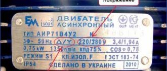
Transformer TSA-30-1
turned out to be wound with aluminum wire (the letter “A” just means aluminum).
Fortunately, there was enough information about him on the Internet, although the reality did not coincide with the passport found for him. According to the passport, one of the windings was supposed to be copper (the PEV-1 wire does not have the letter “A” in the name like the others - PEVA), and I planned not to touch it, but during the work it turned out that this winding was also aluminum . So I deleted it too. Those. Only the primary winding remained intact.
Aluminum foil screen
During the disassembly process, out of curiosity, I unrolled some paraffin paper over the primary winding and wanted to look at it, and came across one turn of foil that was present between the primary winding and the secondary. This roll of foil overlapped with the paper, i.e. it did not close, and only one of the ends was spot welded to the body with a piece of copper wire. This separation is used as a shield against interference, although there is debate about its effectiveness. The transformer is Soviet and the screen was installed at the manufacturer - I did not touch it.
Direction of turns
The turns on the transformer were wound on different coils (left and right) in exactly the same way (not mirrored, but exactly the same). Later it became clear that such winding was made solely for convenience during the subsequent serial connection of windings from different coils. Apparently, for the same reason, the direction of different secondary windings alternates. In this case, it is simply more convenient to place the jumpers between the windings in a series connection on one side.
Metal terminals
The terminals of this transformer are very difficult to solder and tin, since they do not appear to be made of copper. Copper, the better you warm it up, the better it is soldered, and for steel (?) terminals, heating leads to the solder rolling into a ball and flowing from the terminal to the soldering iron tip. It is necessary to catch one of the initial moments of warming up so that the solder remains on the terminal in an acceptable form.
In the transformer under study it was doubly difficult, because aluminum was soldered to the metal terminals. phosphoric acid for soldering.
followed by washing with water and drying on a radiator.
Primary winding
This transformer has two coils, and each winding is divided into two equal parts, which are wound on each of the two coils, with a series connection. It is believed that this way the efficiency is higher and the load is more uniform.
The primary winding consists of two 110v on each coil, connected in series with a jumper. In addition, a small additional winding is connected in series to each of the windings, which I disconnected and used for my own purposes (thus turning it into a secondary winding). The voltage of this additional pair is about 36v (at 230v in the network).
Current transformer connection diagrams
To connect relays and measuring instruments, the secondary windings of the CTs are connected in various circuits. The most common schemes are shown in Fig. 2.5.
Rice. 2.5. CT connection diagrams.
In Fig. 2.5.a shows the basic star connection diagram, which is used to enable protection against all types of single-phase and phase-to-phase short circuits.
In Fig. 2.5.b – partial star connection diagram, used mainly to enable protection against phase-to-phase short circuits in networks with isolated neutrals.
In Fig. 2.5.v – delta connection diagram used to obtain the difference in phase currents (for example, to enable differential protection of transformers).
In Fig. 2.5.g – connection diagram for the difference in currents of two phases. This circuit is used to enable protection against phase-to-phase short circuits, just like the circuit in Fig. 2.5.b.
In Fig. 2.5.d – connection diagram for the sum of the currents of all three phases (zero sequence current filter), used to enable protection against single-phase short circuits and ground faults (discussed in detail below).
In Fig. 2.5.e shows a diagram of a series connection of two current transformers installed on the same phase. With such a connection, the load connected to them is distributed equally, i.e., on each of them it is reduced by 2 times. This happens because the current in the circuit, equal to , remains unchanged, and the voltage per each CT is half of the total. This scheme is used when using low-power CTs (for example, switches and transformers built into the inputs).
In Fig. 2.5.g shows a diagram of a parallel connection of two CTs installed on the same phase. The transformation ratio of this circuit is 2 times less than the transformation ratio of one CT. A parallel connection circuit is used to obtain non-standard transformation ratios. For example, to obtain a transformation ratio of 37.5/5, two standard CTs with a transformation ratio of 75/5 are connected in parallel.
Three-transformer zero-sequence current filter (Fig. 2.5.d)
Used in networks with solidly grounded neutrals (networks with voltages of 110 kV and above) in protection against ground faults. The current value in the measuring element is equal to the sum of the secondary currents:
.
If there are direct and negative sequence components in the primary current, their sum is equal to zero (see Fig. 1.14). The zero sequence components, since they have the same direction, are tripled. Thus, in a measuring element connected to the sum of the currents of three phases, we have a triple value of the zero-sequence current, which allows it to be used as a zero-sequence current filter, i.e. in case of a short circuit to ground, the current in the protection is:
.
However, due to the inequality of the characteristics of the current transformers caused by different errors of the CT phases, an unbalance current appears at the filter output and the value of the current in the measuring element, taking into account this error, will be determined by the relation:
.
For relay protection calculations, the primary unbalance current is usually determined:
, Where:
— uniformity coefficient, taken equal to 0.5 for CTs of the same type (close in characteristics) and 1 for different types;
— aperiodicity coefficient, taking into account the increased value of the magnetizing currents of the short-circuit transient mode and accepted for protection operating without a time delay, equal to 2;
— total error of current transformers;
— short-circuit current at which unbalance is determined.
Selection of current transformers
Initial data.
All current transformers are selected, like other devices, according to the rated current and voltage of the installation and are tested for thermal and electrodynamic resistance during short circuit. In addition, CTs used in relay protection circuits are tested for the error value, which, as indicated above, should not exceed 10% in current and 7° in angle. To check this condition, the information materials of the CT manufacturers and other reference literature provide the characteristics and parameters of the CT:
1) Curves of the maximum multiplicity K10
from the load resistance
ZH
connected to the secondary winding (see Fig. 2.6).
The limiting factor K10
is the largest ratio, i.e. the highest factor, of the primary current passing through the CT to its rated current, at which the total error of the CT (ε) at a given secondary load does not exceed 10%.
In this case, the guaranteed maximum multiplicity at the rated secondary load ZH.nom
. is called the nominal limiting factor.
Rice. 2.6. Ultimate factor curve.
Thus, using the maximum multiplicity curves, it is possible to determine either the permissible load based on a known primary current multiplicity, or the permissible primary current multiplicity based on a known load, at which the total CT error will not exceed 10%.
2) Typical magnetization curves, representing the dependence of the maximum values of induction ( V
) in the core from the effective values of the magnetic field strength
H
at the average length of the magnetic path and a certain cross-section of the core.
Thus, this characteristic is a characteristic of the iron from which the CT is made, and for a specific current transformer it is converted into a current-voltage characteristic, taking into account the number of turns and the geometric dimensions of the core.
It should be borne in mind that a 20% deviation of characteristics from the standard is allowed. Therefore, the calculated characteristic must be reduced in voltage by 20%.
3) Actual magnetization characteristics (called current-voltage characteristics below), representing the dependence of the voltage at the terminals of the secondary winding of CT U2
from the magnetizing current passing through this winding, i.e.
. Using the actual magnetization characteristics, one can also determine I2
and evaluate the admissibility of the resulting error. This characteristic is measured directly on the current transformer used.
4) Load of the secondary winding of current transformers.
The design load of current transformers in protection circuits is determined by the CT connection diagram, relay resistances, and resistances in contact connections. To simplify calculations, the resistances of individual elements are added arithmetically, the transition resistance is taken equal to 0.05 Ohm.
Calculation of the secondary winding of the transformer
The main mistake I made was calculating the secondary winding based on the voltage in the 220v network. Meanwhile, the network voltage during peak loads can drop to 185v - this is almost 20% lower than required! Therefore, when calculating the secondary winding, we must proceed from this indicator - not 220, but for example 180. Otherwise, you can seriously miscalculate.
When calculating the voltage in the power supply transformer, the following should be taken into account:
- Minimum network voltage ~180 V
- Voltage drop across the diode bridge is more than 2 V
- Voltage drop across the stabilizer - for example 3 V
- Voltage drop on the secondary windings with increasing load current (multiply by an average of 1.02 - 1.06, depending on the maximum current)
The figure below shows the voltage on one element of the KBU801
at a current of 8 A it reaches 1.08 V. I.e. across the entire bridge the voltage drop will be more than 2 V (click to enlarge).
To clarify the number of turns per volt in the secondary winding, you can make a temporary control winding
(for example, 10 turns) and measure the voltage it produces (be sure to check the voltage in the network!). Then divide these 10 (turns) by the resulting voltage. This gives us the number of turns per volt.
IMPORTANT!
It is necessary to divide the turns of the control winding by its voltage, and not vice versa!
Example
.
A supply voltage of 20 V with a maximum constant current of 2 A is required.
A rough estimate looks something like this:
20 + 3 = 23 V (voltage drop across the stabilizer)
23 + 2.2 = 25.2 V (voltage drop across the diode bridge)
25.2 / 1.41 = ~17.3 V (we convert the DC voltage after the diode bridge with a capacitor into the required secondary variable)
17.3 * 1.06 = ~18.4 V (we take into account the voltage drop in the winding at maximum load current)
If we have, for example, 4.4 turns per volt at an ideal ~220 V, then at a voltage of ~180 V in the network, we will need
18.4 * 4.4 = 81 turns (for ideal voltage ~220 V)
81 * (220/180) = 99 turns (for peak voltage drop up to ~180 V)
Those. at ~220 V in the network, the secondary winding containing 99 turns will produce about ~22.5 V (and if the network drops to ~180 V, the required ~18.4 V)
Transformer connection diagrams
To implement overcurrent protection, various current transformer (CT) connection schemes are used. Which scheme will be used depends on where exactly the CTs are used. For example, in urban networks a “full star” scheme can be used, and in rural networks a “partial star” scheme can be used. In differential and other protections, transformers can be connected in a triangle, and relays can be connected in a star.
Full star
Connection diagram for current transformers “full star” (Fig. 1), in which CTs are installed in all three phases, and the neutral points of the secondary windings are connected in series with one neutral conductor. With this connection, currents flow in the current relay (indicated in the figure as I, II and III) equal to the currents passing through the primary windings of the CT, divided by the transformation ratio nT. In the neutral wire, the geometric sum of all currents In.p. flows, which, if these three currents are equal, is equal to zero.
The circuit coefficient Kcx, which is the ratio of the current in the relay to the current in the phase, is equal to 1, since the current in each of the three relays is equal to the current in the corresponding phase.
Partial star
In Fig. Figure 2 shows the “partial star” circuit. The difference between this scheme and the previous one is that the CTs are installed only in one of the three phases. Otherwise, the circuit is similar: the relay windings (I and III) and the secondary windings of the CT are installed in the same way as in a full star. The geometric sum of the currents of the two phases to which the transformers are connected flows in the neutral wire.
Just like for the previous scheme, the coefficient Ksh = 1.
Triangle
In Fig. Figure 3 shows a diagram for connecting overcurrent protection devices in a delta. With this connection scheme, the secondary windings of the CT are connected in series with opposite terminals, forming a triangle. Thus, a current flows in each of the relays equal to the geometric difference between the current in the corresponding phase and the current in the phase following it:
In this case, Ksh = , since the current in each of the relays is several times greater than the current in the corresponding phase.
"Eight" ("incomplete triangle")
In Fig. Figure 4 shows the CT connection according to the figure-of-eight (incomplete triangle) diagram. In this circuit, the transformers are installed in only two phases, and the secondary windings are connected to each other by opposite terminals. The current in the relay is equal to the difference in the currents of the two phases in which the transformers are installed. With this connection scheme Ksh = 2.
Series and parallel connection of current transformers
Figure 5 shows a diagram of the series connection of current transformers. With this connection of the secondary windings of the CT with the same transformation ratio, the current strength is the same as when only one of the transformers is connected to the circuit, while the load is distributed equally among the two. This scheme can be used when using low-power transformers.
When connecting current transformers according to the diagram shown in Figure 6, the current in the relay is equal to the sum of the currents in the secondary windings of each transformer. Typically, this circuit is used to obtain non-standard transformation ratios.
Winding
I wound four parallel wires at the same time. As a result, I got four windings on each coil in each row. This number of windings makes it possible, by connecting them in series (or parallel), to combine the required voltage (and current).
For a laboratory power supply used as a work tool, this is the most convenient option.
IMPORTANT!
For a transformer with an “O” shaped core, with two coils on the right and left (such as the one discussed in this article), it is best to divide each winding into two (identical) ones, wound on different coils and connected in series. In this case, the efficiency will be higher.
BY THE WAY
when laying on the frame, it is advisable to slightly bend the wire outward before each bend at the corners, so that the turns do not then move away from the frame, forming a gap in which the winding density deteriorates. I additionally pressed down the wire with a pine block after each bend on the frame.
Calculation of wire length.
Before winding, it is necessary to measure the width of the frame and the width of the window between the coil frames (or frame and core). After this, you need to calculate the length of the wire and take into account its diameter (with varnish insulation!). If winding occurs without disassembling the core, by threading the wire through the window, then a piece/pieces of wire of the required length will need to be “bitten off” in advance, so it is important not to make a mistake. If the wire is thin enough (for example, less than 0.5 mm) and long, then it makes sense to make a thin shuttle on which to wind the wire of the required length - this will make it easier to drag it through the window.
Here, for example, the internal length of the frame was 54 mm, and expecting to lay 52 turns of wire with a diameter of 1 mm, I did not guess - I had to partially overlap the last half turn (apparently I did not take into account the thickness of the varnish insulation). See the picture (click to enlarge):
When calculating the capabilities of a window, you need to take into account the total thickness of the insulating pads made of paper or varnished fabric between the windings.
To accurately calculate the required length, you need to make a control turn and measure its length. At the same time, in each next row the turn will be a little longer (the thickness of the bottom row and the thickness of the inter-row insulating spacer will affect). You need to understand that, for example, with 50 turns, a length error of one millimeter per turn will give an error of 5 cm at 50 turns. You also need to take into account the margin for conclusions (I added 10 cm on each side to the total length of the pieces, i.e. only 20 cm - this was enough for both conclusions and a possible error).
Method for connecting parallel windings of a transformer
I am often asked the question: “Is it possible to connect identical secondary windings of power transformers in parallel?” The question is certainly correct, and it needs to be answered. Nowadays, in outdated equipment you can find a large number of ready-made factory-made power transformers, which radio amateurs adapt to their needs. Very often these transformers are not quite suitable in terms of parameters, for example, the required load current.
But if the transformer has several identical windings, the idea arises to increase the output current by connecting these windings in parallel. It would seem that connect the terminals of identical windings to each other and that’s it! But it's not that simple. First, the windings must be connected in phase. To check the in-phase of the secondary windings, we connect one of the terminals of the two windings, connect the transformer to the network and measure the voltage between the remaining free ends. If this voltage is close to zero, it means that the windings are connected in antiphase in series.
When the terminals have double the voltage of one of the windings, they are connected in phase in series. In the first case, the free ends of the windings can be connected together and a parallel connection of the windings can be obtained. In the second case, the ends of one of the windings need to be swapped. However, the slightest non-identity of the windings can affect the parameters of the power transformer: its overall power and efficiency decrease, and the heating of the windings increases.
In fact, it is possible to connect the windings of such transformers in parallel, during the manufacture of which special measures are taken to ensure that the windings are identical. For example, the passports for transformers such as TPP (semiconductor equipment power supply transformers) indicate the permissibility of parallel connection of identical windings. Most often, amateur radio designs are powered by direct current, so the problem of connecting windings in parallel is best considered in conjunction with a rectifier.
Let's take, say, a unified transformer TN-60 (incandescent transformer), which has 4 identical secondary windings of 6.3 V each (two windings also have taps of 5 V), each designed for a current of 6 A. To obtain currents four times greater, it is necessary to connect the windings as shown in Fig. 1 (connection of windings with half-wave rectification). Since, due to design variations in winding parameters, windings may have slightly different voltages, greater current consumption (with identical diodes) will be from the winding whose voltage is higher.
Diodes allow you to decouple the windings from each other, i.e. Now each winding works only on the common load, and not on the other winding. As a result, we received a rectified voltage from four windings with a maximum load current of 24 A (only a quarter of the total load current will pass through each diode). The full-wave rectification circuit is shown in Fig. 2. This connection of the winding terminals also provides independent power supply to the load. In the case of parallel connection of an odd number of windings, only half-wave rectification is possible.
To power various designs, a voltage of 12 V is often used, so the connection of windings for such applications can be made according to Fig. 3. In this case, half the load current will pass through each diode. To obtain a stabilized output voltage of about 13.8 V, accepted as a standard in radio transmitting equipment, it is necessary to use stabilizers with a low voltage drop on the control element [1, 2].
The minimum required voltage drop across the control element of such stabilizers is about 0.5 V. It is set at the maximum load current by selecting the capacitance of the filter capacitor after the rectifier. The larger the capacitance of this capacitor, the greater the output current can be “taken” from the stabilizer at a given input voltage.
Direction of turns
I had difficulty finding information about the direction of the winding turns - for this I had to refresh my school physics course (the gimlet rule, etc.). Although this question inevitably arises for a beginner.
The main rule is that the direction of the winding turns does not matter
... as long as there is a need to connect the windings to each other (series or parallel), or in the case of using a transformer in some devices where the signal phase is important.
It doesn’t matter in which direction you wind the turns - what matters is how the windings are then connected
Series connection of windings
When connecting the windings of a transformer in series, you need to mentally imagine that one winding is a continuation of the other, and the point of their connection is a break in a single winding
, in which
the direction of rotation of
the turns around the core remains unchanged (and of course cannot turn in the opposite direction!).
In this case, any terminal of the winding can be the beginning or the end, and the direction of rotation itself can be any. The main thing is that this direction remains the same for the connected windings.
In this case, the movement of the connected windings from top to bottom of the coil or from bottom to top does not matter (see the figure - enlarged by clicking the mouse).
In transformers in which the core is shaped like the letter “O” and the coils are wound on two frames on the right and left, the same rules apply. But for ease of understanding, you can mentally “tear” the core (from above or below), and imagine that it is straightened into one rod - this will make it easier to understand how one winding passes into another while maintaining the direction of rotation of the turns (clockwise or counterclockwise) . See the picture below (the picture can be enlarged by clicking the mouse).
Parallel connection of windings
When connecting in parallel, the length of the wire in the windings is important.
Even with the same number of turns, different windings may have different wire lengths (the winding that is closer to the middle will be shorter, and the one further away will be longer). As a result, cross-flows
.
If parallel connection of the windings is assumed, then it is better to wind them simultaneously in two (three, four...) wires. Then they will be the same length, which will eliminate cross-flows as much as possible during their further parallel connection.
Winding several wires is also used in the absence of a wire of the required cross-section (a large cross-section is collected with several smaller wires).
Checking the direction of turns using a battery and a multimeter
If you have a transformer in which you need to connect two windings in series, but the direction of the turns is not visible or known, you can apply a DC pulse from a battery to one of the windings, observing the voltage surge on the other winding.
When the voltage surge at the moment of connecting the battery on the multimeter (on the second winding) is in “+”, then the connection points of the windings will be any “+” and “-” of different windings (for example, “+” of the multimeter and “-” of the battery, or vice versa) . The other two ends will be the outputs of these windings after connection (see figure - click to enlarge).
Direction of turns on different coils
I repeat - the direction of winding is not important, it is the connection of the windings that is important.
There is one “but” though. If we talk about convenience, then on this type of transformer (with a core in the shape of the letter “O” and two coils), it is more convenient to wind the right and left coils in the same way (not mirrored, but identically). In this case, it will be more convenient to install jumpers when connecting two windings in series on different coils - the jumpers will be on one side, and not across the entire frame from top to bottom.
See the picture (to enlarge, click on the picture):
Connection of transformer windings (parallel, series and mixed connection).
Video on this topic:
A transformer is an electrical device that is capable of converting electrical energy through electromagnetic fields. The design of a classic transformer is a magnetic circuit consisting of plates (with good ferromagnetic properties) and having a closed circuit (can be round, W-shaped, U-shaped). Windings of copper wire are wound around this ferromagnetic core. Typically these are the primary and secondary windings.
The meaning of the transformer is that when alternating current is supplied to the primary winding, an alternating electromagnetic field is formed around the core. This field generates EMF (electromotive force) in the secondary winding. The value of the current and voltage on the secondary winding will depend on the proportionality of the number of turns between the primary and secondary windings. But the primary winding must also be designed for its current and voltage values, since the incorrect number of turns and cross-section of the winding wire affect the efficiency of the transformer (efficiency).
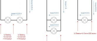
The transformer windings can be connected to each other in a certain way. The connection of transformer windings can be parallel, series or mixed. So, we have a transformer that has two primary windings and two secondary windings. Its primary windings are designed for alternating voltage of 110 volts. Secondary 6 volts. If we have a 220 volt network, then we must connect the primary windings in series (110 + 110 = 220), after which we can safely supply 220 volts to this combined primary winding. Although if our network turns out to be 110 volts, then this voltage can be applied to any winding designed for 110 volts.
So, on the secondary winding we will each have an alternating voltage of 6 volts. If we combine them in series, we end up with double the voltage of 12 volts. If we connect these secondary windings in parallel, then in this case the voltage will remain the same, namely 6 volts, but the current will double. Please note that the number of turns of the transformer affects the voltage, and the cross-section of the winding wire affects its current strength. A prerequisite for a parallel connection must be the same number of windings. If this sameness does not exist, then the voltage of this difference will negatively affect the operation of the transformer, reducing its efficiency and causing additional heating of the core.
The mixed type connection of the transformer windings implies simultaneous connection in both parallel and series ways. In this case, both the current on the windings and the voltage will increase. What will happen if we connect transformer windings that have different cross-sections? If this is a parallel connection, then this is equivalent to the fact that the cross-section of the windings will simply be summed up (the current strength will increase, which corresponds to the total, total cross-section of the winding wire). If this is a series connection of the transformer windings, then the final current strength will correspond to the winding with the smallest wire diameter.
PS The most practical connection of transformer windings can be considered the option when, through a series connection, you can select the most suitable voltage on the secondary winding. We wind the secondary winding with taps that have a certain pitch (for example, we make 10 windings, each with 3 volts). As a result, we are able to obtain any voltage from zero to 30 volts in 3-volt increments. In this case, we have the greatest energy savings, in contrast to the method when, having only 30 volts at the output, we create the required voltage due to the stabilizer circuit (excess voltage is simply consumed in heating). Please note that when connecting the transformer windings, their direction (polarity) matters.
No-load current
If everything is done correctly and the transformer core was assembled (at the factory) with high quality, then the no-load current (current of the primary winding, with the secondary winding completely disconnected from the load) should be within acceptable limits.
In my case, this current was 27 mA, which is just an excellent indicator.
The ammeter must be connected to the break in the network cable connected to the primary winding and, preferably connecting the multimeter probes, connect the transformer to the network. Then disconnect the probes and observe the readings. It is necessary to connect the probes before connecting them to the network to avoid failure of the multimeter, because The transformer may have a large starting current (tens of times higher than the rated current).